3D Printing

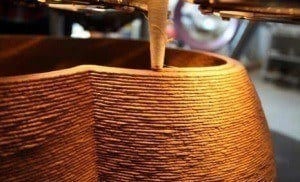
3D printing technology uses the latest “ultra-cool” movement. Ever since we heard about 3D printing, we remember the small 3D printers. It began to imagine how the world would look if 3D printing became such a common procedure as paper printing.

There’s a world full of home-made toys, dishes, utensils, and lots more. What if 3D printing offer excellent solution with solve the issue of shelter around the globe. What if there could provide a feasible solution to a 3D print houses?

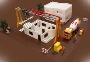
The idea of ContourCrafting comes when CEO offer a very insightful TED talk. The Professor Behrokh Khoshnevis, from the University of Southern California, is the man that have built this awesome concept. In simple words, he wants to make a 3D printer within 20 hours. The vast 3D home builder creates the entire building, from the foundation, floor, ceiling, and plumbing. At the beginning, we thought it could build the main block of the building.

The 3D printer from ContourCrafting is far more crafted than this. It would build houses in such a way that you’d only require to put the windows and the doors in the cutouts. The vast construction robot left this. Maybe one wouldn’t like living in such a home built by a gigantic 3D printer.

But almost 1 billion people don’t have stable shelter. Therefore, do you think, they’ll think twice before moving in? It can be an immediate and most urgent use for 3D printed home. But I can imagine that the rest of us, or those with money, can print their own house in less than one day.

Inspiring 3D printers that will reshape the construction

Right from the start, we were confused that how to build big buildings with hundreds of flats? How are they going to achieve that? But the CountourCrafting guys created the model of a 3D printer. It’s building that capable of designing everything. And something that surprised was some 3D printer capable of climbing and finishing the printing to a next level.

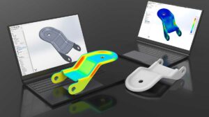
The technology seems very impressive and can build more advanced buildings using advanced designs. We use a perfectly calculated geometry using the strong material. The house-building with 3D printers can replicate historic or progressive buildings. How cool, isn’t it.

It does sounds excellent on paper, but what’s the reality…

Behrokh Khosnevis says, this technology is far more secure and safe than current construction methods. He said that the 10,000 workers die each year in the USA and 400,000 get injured during construction. But with 3D construction printers, we could eliminate and decrease lot of the time that require to build a house. There are drawbacks that we can’t ignore. Let’s discuss them.

3D printing house to build in 20 hours!

Imagine how many jobs get lost if the technology were become mainstreams. We have a team that supports a civilization and rely on the technology. Thus, with being more automated, it manually runs using this technology. Few houses are built using this concept, but it will not gain mass appeal as the government requires to keep the population employed. But again, the same thing happened when the Industrial Revolution began.

The people were afraid that they would lose jobs as technological devices were there to take tasks from humans. But when we look behind, we see that humanity has found a place for everybody. It can be an issue for the moment, but imagine that by 2050 or beyond 3D printed homes not be just a “cool concept”. Instead, it could be something ordinary. The appearance of the Web won’t kill jobs, it could change the world. The 3D printing won’t kill construction, it can reshape in near future.

What a brave new world it could be?

The technology is excited that it wants to be a part of it. One can see 3D printed houses around and people living in them. One can see huge 3D printers outside the towns. There could be building from the ground homes for everybody. Let’s imagine using this technology, one can build houses on other planets as well. Get connected, if you’re looking for a leading Australian design and drafting service company, here we are to help you solve your problem.

Is 3D printed house strong?

The strength of a 3D-printed house depends on various factors such as the materials used, the printing technology, the design, and the structural integrity. Generally, 3D-printed houses can be quite strong and durable if they are designed and constructed properly. Many construction companies are exploring the use of high-strength materials like concrete, composite materials, and even advanced polymers for 3D printing homes. Additionally, the ability to create intricate geometries and customized designs through 3D printing can sometimes result in structures that are more robust than traditional construction methods. However, it’s essential to ensure that the printing process is carefully controlled and monitored to maintain quality and structural integrity. Overall, with the right materials and techniques, 3D-printed houses can indeed be strong and reliable.

What are the disadvantages of 3D printed houses?

While 3D printed houses offer numerous advantages, they also come with some disadvantages:
Limited Materials: Currently, most 3D printed houses are constructed using materials like concrete or synthetic materials, which may not be as environmentally friendly as traditional building materials like wood or brick.
Limited Design Flexibility: While 3D printing allows for innovative designs, it can also limit the architectural freedom compared to traditional construction methods. Intricate designs or non-standard shapes may be challenging to achieve.
Quality Control Challenges: Ensuring the structural integrity and quality of a 3D printed house can be challenging, especially if the printing process encounters errors or inconsistencies. Quality control measures need to be robust to guarantee the safety and longevity of the structure.
Dependency on Technology: 3D printing technology is still evolving, and reliance on it for construction means being dependent on the advancements and reliability of this technology. Technical glitches or failures in the printing process can lead to delays and added costs.
Regulatory Hurdles: Building codes and regulations often lag behind technological advancements. Incorporating 3D printed houses into existing regulatory frameworks may require significant adaptation and approval processes, which can be time-consuming and cumbersome.
Scalability Challenges: While 3D printing has the potential to revolutionize construction, scaling up the technology for mass adoption on a large scale presents logistical and infrastructure challenges. The current scale of 3D printing is limited, and widespread adoption would require significant investment and infrastructure development.
Skilled Labor Requirement: Despite automation in the printing process, skilled labor is still required for setup, maintenance, and finishing work. Ensuring an adequate workforce with the necessary skills to operate and maintain 3D printing equipment can be a challenge.
Perception and Trust: Acceptance of 3D printed houses among consumers, builders, and regulators may be hindered by skepticism or distrust regarding the durability, safety, and longevity of these structures. Building confidence in the technology and its capabilities is crucial for widespread adoption.
Cost Considerations: While 3D printing has the potential to reduce construction costs in the long run, initial setup costs, including investment in printing equipment and infrastructure, may be substantial. Additionally, the cost-effectiveness of 3D printing may vary depending on factors such as project size, location, and material availability.

3D Printer

3D Printer has made things possible where the sky is just the limit. The 3D Printer is now capable of printing objects as long as 100 feet, 20 feet wide and 10 feet high. A big guy up to 12 meters was built out of the object. He mainly uses the local material that uses less energy as required and makes a house almost zero cost. It offers quick and inexpensive relief to the affected areas in the future. Due to which the rapid population growth and a surge satisfied housing demand.

With increasing material manufacturing on Earth, it uses planets that rapidly build houses and tightening budgets that are very interesting viewpoints. In space, it provides us with a lot of design flexibility with a unique and highly functional unit. It cannot be assembled with other building methods and make a way out.

The world’s largest 3D printer

On this planet, 3D printing houses have become more common. The United Nations predicts that the world’s future will add almost 100,000 new homes a day within five years. Compared with other houses that are cheap and fast building, they are developed for earthquakes, cyclones, floods, and other natural disasters to recover quickly. In case of emergency costs, energy and material restrictions are very large, so people never need unusual sources of inspiration.

We can say that no one can do better than potter wasps. It methodically comes with countless layers of mud covering layers, eventually forming nest-like pottery. For its part, the industrious insects may be the world’s smallest and the most environmentally-friendly 3D printers.

One of the widest Italian engineering company manufacture varieties of WASP 3D printers. In the current plan, they build a shelter for human habitation. Additionally, the company exhibit a 4.5-meter printer that can handle simple and highly flexible material, including mud, clay or other natural fibres. Now, the company is at the peak to create 3D printers. And the 12 meters high 3D Printer is called the Big Delta.

The company pass-through 3D printing houses and provide health assistance with affected areas covering the walls of houses repellents. Since 3D printing, such as a house in shape, size and material selection are very resilient. They have the potential to meet the needs of developing countries with affected areas. WASP has represented the southern coast of Sardinia Iglesias town which has the least interest in the Big Delta. In recent times, they have used Printer built out of housing units. Using the large Printer, one can accelerate innovation with prototype development in various sectors and achieve their dreams. What are your plans about designing something with a 3D Printer? Let’s connect and discuss your idea in brief.

Which is the largest 3D printer?

The title of the largest printer in the world can vary depending on different criteria such as print size, application, or technology. However, if we’re talking about large-format printers used for things like billboards, banners, or building wraps, one of the largest models available is the EFI VUTEk 5r+. It’s capable of printing on substrates up to 5 meters wide, making it suitable for producing exceptionally large graphics.
For industrial printing, particularly in fields like construction or aerospace, large-scale 3D printers like the BigRep ONE or the Titan Robotics Atlas can also be considered some of the largest printers in the world due to their ability to create objects with significant dimensions.

What is the largest thing ever 3D printed?

the “BAAM” (Big Area Additive Manufacturing) 3D printer, developed by Cincinnati Incorporated and Oak Ridge National Laboratory, holds the record for printing some of the largest objects. This printer is capable of printing objects as large as a car or even a house. For example, in 2014, they printed a car using this technology. However, specific records can change as technology advances, so there may be even larger objects printed since then.

Finite Element Analysis

Engineering problems with Finite Element Analysis (FEA)

With finite element analysis or FEA services, you can easily find an apt solution for any complex engineering problem by subdividing your problem into small and manageable finite elements. FEA services involve the use of finite elements to successfully reduce the complex differential equations of a structure to a set of easily solvable linear equations.[/fusion_text][fusion_text]In short, finite element analysis can be described as an engineering technique that is used to predict the response of structures and materials to applied loads such as temperature, force, displacements and vibration. Before you develop a design, you can model it, evaluate its performance and address failure points with FEA services.

Engineering problems with Finite Element Analysis (FEA)

Today, almost every engineering discipline requires finite element analysis. Industries like manufacturing, plastics, electronics, energy, geotechnical aerospace, automotive, biomedical and chemicals regularly use FEA services. Apart from playing an integral role in evaluating classical static structural problems, FEA is also widely used in radiation problems, mass transport, dynamics and heat transfer amongst others.

ASTCAD offers cutting-edge FEA services

If your organization wants to optimize a new design, verify the fitness of an existing facility or evaluate a new concept, then you can opt for finite element analysis services from ASTCAD Design & Drafting. Accurate FEA services require the skills of experienced analysts and advanced technologies. ASTCAD can provide you with world-class FEA services at an affordable price. Over the years, ASTCAD has earned the reputation of having the world’s best engineers and access to sophisticated analysis tools.

Get complete FEA solutions from ASTCAD

ASTCAD have the best personnel, latest equipment and cutting-edge tools to perform comprehensive finite element analysis, such as:

  • Mechanical drop and impact analysis
  • Modal analysis and forced vibration (Sine and Random)
  • Thermo-mechanical analysis (Fatigue and Creep)
  • Parametric sensitivity analysis
  • Warpage analysis
  • Material stiffness analysis
  • Shock Spectrum analysis

Top 5 benefits of outsourcing FEA services

By outsourcing finite element analysis services to ASTCAD, your organization can leverage the following five benefits:

  1. Drastically reduce your development time and the cost of new products
  2. Get valuable product reliability insights
  3. Improve the quality of the product
  4. Easily conduct and simulate conditions like temperature cycling, drop, vibration and fatigue life tests
  5. Investigate and quantify different design scenarios ( varying geometries, changing materials etc)

Engineering problems with Finite Element Analysis (FEA)

By partnering with ASTCAD for FEA services, your company can enjoy fast, accurate and professional finite element analysis services at a low cost. With access to expert FEA structure stress analysis, engineering design and simulation using CAD, you can solve your engineering problems. From the initial concept to the final product launch, you can be sure of 100% customer satisfaction, when you partner with ASTCAD for FEA services.

Finite Element Analysis (FEA) is a powerful numerical method used to solve engineering problems by simulating the behavior of structures or systems under various conditions. Here’s a general approach to solving engineering problems with FEA:

  1. Problem Identification: Clearly define the engineering problem you want to solve. Identify the objectives, constraints, and desired outcomes of the analysis. Determine the specific components or systems that need to be analyzed using FEA.
  2. Geometry and Mesh Generation: Create a digital model of the structure or system using CAD software or FEA-specific pre-processing tools. Define the geometry, including dimensions, shapes, and boundaries. Divide the model into smaller elements and create a mesh, ensuring appropriate element size and quality.
  3. Material Properties and Boundary Conditions: Assign material properties to the elements, including properties such as elasticity, density, thermal conductivity, and other relevant parameters. Apply appropriate boundary conditions, such as fixed supports, loads, displacements, or thermal conditions, based on the physical behavior of the system.
  4. Element Selection and Analysis Type: Choose suitable finite elements based on the problem type, such as truss, beam, shell, or solid elements. Select the appropriate analysis type, such as static, dynamic, thermal, or nonlinear analysis, based on the nature of the problem and the behavior of the structure.
  5. Solver Configuration: Set up the solver parameters, including convergence criteria, time steps, and solution options. Specify any additional assumptions, simplifications, or idealizations required for the analysis.
  6. Solve and Post-Processing: Run the analysis using the FEA software. The software will calculate the response of the structure or system based on the applied loads, boundary conditions, and material properties. Once the analysis is complete, examine the results to understand the behavior of the structure, including stress, strain, displacement, temperature distribution, or other relevant output parameters.
  7. Interpretation and Validation: Analyze and interpret the results in relation to the problem objectives. Validate the results by comparing them to theoretical calculations, experimental data, or industry standards. Assess the accuracy, reliability, and limitations of the FEA analysis.
  8. Optimization and Design Iteration: If the analysis reveals areas of concern or performance gaps, consider design iterations or optimizations to improve the structure’s performance. Modify the geometry, material properties, or boundary conditions as needed and repeat the FEA analysis to evaluate the effects of the changes.
  9. Documentation and Reporting: Document the analysis process, including the problem statement, assumptions, modeling details, input parameters, results, and conclusions. Prepare a comprehensive report that summarizes the analysis methodology, findings, and recommendations.

Have you outsourced mechanical engineering services before? If yes, how did it go? Would you consider outsourcing FEA services? Let us know your thoughts, views and questions on outsourcing to ASTCAD by leaving a comment in the box below. We, at ASTCAD love, to hear from you!

3D Scanners

Reverse Engineering Using 3D Scanners to Generate CAD Models

The engineers of today lives and thrives in a 3D CAD model world. The CAD models offer the best design versatility and a direct link to rapid prototype development. The CAD models are essential where reverse engineering use 3D scan data to generate CAD models.

Here, the object exhibits a complex shape when using a 3D model that does not exist for a component. The 3D scan equipment captures the physical geometry that transforms it into a 3D digital model. The CAD engineers and industrial designers create a task to adapt and maintain parts that integrate into the design.

Reverse Engineering Features:

  • Designing a new part to fit a legacy part.
  • Obtain CAD data that captures an object’s design intent.
  • It accurately offers performance surfaces.
  • It helps in updating CAD models of your tooling to match shop-floor changes.
  • Get ready to redesign a part without manufacturing defects.
  • It supports modernising your manufacturing process.
  • It offers animation or visualisation.
  • Perform a dimensional along with comparative analysis of an object.
  • Performing FEA or CFD analysis.

Reconstruct the damaged part digitally to reproduce it in its originally intended form. It uses rapid prototyping or CNC technologies. The 3D scanning technologies come in different shapes and forms. Additionally, some stationaries require the part to be brought into the scanner.

The scanning laser technology has conducted surveys of the 3D contour of the surface. It helps to save the geometrical data to a CAD model. The 3D scanners scan vehicles, aeroplanes, ships, submarines, historic monuments, buildings, sculptures, consumer products, and more.

Let’s say a complex 3D scanning problem is the 3D scan that is performed by Creaform, mainly using HandyScan3D. It’s a unit combined with a long-range scanner in the United States Marine Corps War Memorial replica. It is located at the Marine Corps Recruit Depot in South Carolina.

The project’s primary purpose comes with historical preservation so that the memorial could recreate in the future if it suffers damage. The handheld scanner mostly used the application capable of scanning ½ million points per second. With up to 30 sq. resolution accuracy and 60 sq. volumetric accuracies.

HOW DO 3D SCANNERS WORK?

Laser scanning is a process where the scan passes a laser line over the surface of an object. Later the surface data was captured by a camera sensor mounted in the laser scanning. It records and saves three-dimensional information to a model.

The regions of an object are scanned once. It allows thousands of closely positioned points to be surveyed at once. Currently, several laser scanners exist, including the line, patch, and spherical. Also, Laser scanning is performed without making contact with the object.

Talking about digitising, it’s a contact-based form of 3D scanning in which a point or ball probe is scanned over points on the object’s surface. It is more accurate for industrial reverse engineering applications. The 3D laser scanning is more desirable for non-standard or organic shapes where the sculptures or person’s face is scanned. Digitising limits to smaller objects, while 3D laser scanning is more versatile.

It is used to scan large objects like vehicles or buildings. White light scanning, CT scanning and photo image-based systems are mainly used as alternate methods for 3D scanning applications.

LIMITATIONS OF 3D SCANNING

Bright white light sources can be detrimental to 3D scanning technologies, requiring many outdoor laser scanning projects to be conducted after daylight hours.

3D scanning works better on matte finishes than highly reflective surfaces, which reflect white light. Spray-on solutions exist that can effectively dull a surface before scanning.

Some intricate objects, such as large sculptures, require stationary and handheld scanners to reconstruct the entire surface. This process requires a detailed and intricate image and position registration – fortunately, many companies exist that have mastered this process and provide solutions for these complex problems.

INSPECTION WITH USING 3D SCANNING TECHNOLOGIES

Inspection is another valuable use of 3D scanners. It allows parts to be rapidly checked and ensures manufacturing tolerances. 3D scanning technologies use First Article Inspection, where high accuracy comes with fine resolution. It requires verification with a physical part that produces according to production drawings.

The scanners inspect a “final” part so that its models and drawings can generate blueprints for re-manufacturing a part. The Inspection of aging components or systems is possibly used with technologies. For example, modifications are required to update the vehicle in foraging ships or aircraft. It uses reverse engineering that uses laser-based 3d scanning technologies that produce physical dimensions of the vehicle or its parts.

It comes with a prime example that comes with reverse engineering. It comes with an F-15 test plane used for NASA engineers. It was conducted by Direct Dimensions, Inc. (DDI) in 2006. Additionally, the engineers at NASA modify the test plane and obtain in-flight data to verify design improvements.

Due to its daunting costs, it associates along with full-scale testing. It comes with the danger associated with measuring pressure on a plane that moves at supersonic speeds. It is used to chase planes with the help of reverse engineering. Before testing and implementation, it could simulate the design changes and use computational fluid dynamics (CFD) software. DDI mainly uses the FARO LS 3D laser system, along with a portable scanner designed for scanning the shape of large objects.

It can acquire up to 120,000 points per second over ranges of up to 80 meters. The technology allows DDI and quick and accurately capturing the jet’s exterior shape with an accuracy of +/-6 millimeters. The raw comes with 3D scanning data that offer a high-resolution point cloud. It uses a laser that reflects spots off the plane’s surfaces. It can digitally process and convert to CAD format. Over 50 individual scans from different positions generated 50 million data points used in reverse-engineering of the F-15.

What are 3D scanners used for?

3D scanners are used in a variety of fields for capturing the three-dimensional shape and appearance of real-world objects or environments. Here are some common uses:
Industrial Design and Manufacturing: In product design and manufacturing, 3D scanners are used for quality control, reverse engineering, and prototyping. They can capture precise measurements and detailed geometry of physical objects, allowing manufacturers to replicate or modify existing designs or create new ones.
Archaeology and Cultural Heritage: Archaeologists and historians use 3D scanners to document and preserve artifacts, sculptures, and historical sites. By creating digital replicas, researchers can study these objects without risking damage to the originals. Additionally, 3D scanning technology aids in the restoration and conservation of cultural heritage sites and artworks.
Medical Imaging and Healthcare: In medicine, 3D scanners are utilized for various purposes, including custom prosthetics and orthotics, dental applications (such as creating dental crowns and implants), and surgical planning. Medical professionals can capture detailed anatomical data to assist in diagnosis, treatment planning, and patient care.

What is a 3D digital scanner?

A 3D digital scanner is a device used to capture the three-dimensional shape and appearance of real-world objects or environments and create digital representations of them. These scanners use various technologies and methods to collect data points from the surface of the object and then process this information to generate a 3D model.
There are several types of 3D digital scanners, including:
Laser Scanners: These scanners emit laser beams onto the object’s surface and measure the reflections to determine its shape and contours. Laser scanners can capture highly accurate and detailed 3D data, making them suitable for applications such as industrial design and manufacturing.
Structured Light Scanners: Structured light scanners project a pattern of light onto the object and use cameras to capture how the pattern deforms on its surface. By analyzing these deformations, the scanner can calculate the object’s 3D geometry. Structured light scanners are often used in applications like 3D printing, animation, and medical imaging.
Photogrammetry Systems: Photogrammetry involves taking multiple photographs of an object from different angles and then using specialized software to analyze the images and reconstruct the object’s 3D shape. Photogrammetry systems are versatile and can be used with standard digital cameras, making them accessible for various applications, including archaeology, cultural heritage preservation, and virtual reality content creation.
Time-of-Flight (ToF) Scanners: ToF scanners use infrared light to measure the distance between the scanner and the object’s surface. By measuring the time it takes for the light to travel to the object and back, the scanner can create a depth map of the object’s surface, which can then be used to generate a 3D model.

CAD Platforms in Product Designs

CAD Platforms in Product Designs

In the present age of rapidly computerized applications and CAD product designs, it is very likely that many future electromechanical products will have an embedded processor within them. Consider these two examples:

  • Several decades ago, the automobile industry designed automobiles with carburetion technology. This was been replaced by computer-driven electronic ignition systems. Likewise, manual braking was replaced by computer-assisted “antilock braking.” Recently, the concept of a computer-operated driverless car was mentioned as becoming a real possibility. The idea is not too far-fetched when you consider that computer-managed aeroplane navigation is a mature technology.
  • Many products such as copying machines, refrigerators, HVAC systems, and robotic systems provide real-time electronic communication between the customer and the manufacturer. For example, downtime for copying machines is significantly reduced because the product is proactive in sensing impending failures and calling for service. This makes the customer believe that the product is very reliable and virtually failure-free.

These two examples illustrate the trend in product development which combines CAD hardware design, embedded computer technology, and IT (Information Technology) into a package which changes a “dumb product” into a “smart product”. A smart product, therefore, communicates with both its manufacturer and with its customer in a manner which improves the functionality of the product and provides optimum performance of the product.

Best Importance of CAD Platforms in product designs Service

Computer-Aided Design (CAD) platforms play a crucial role in modern product design and development processes. Their importance stems from the numerous advantages they offer, which significantly enhance the efficiency, accuracy, and overall quality of the design process. Here are some key reasons why CAD platforms are essential in product design:

  1. Visualization and Conceptualization: CAD software allows designers to create detailed and realistic 3D models of products. This visualization capability helps designers and stakeholders better understand the concept and appearance of the final product before any physical prototypes are built. This leads to more informed design decisions and reduces the risk of costly design changes later in the process.
  2. Design Iteration and Flexibility: CAD platforms enable rapid prototyping and design iteration. Designers can easily modify and refine designs, test various configurations, and explore multiple ideas quickly and efficiently. This iterative approach leads to better designs and innovative solutions.
  3. Precise and Accurate Measurements: CAD software ensures high levels of accuracy in measurements and dimensions. This is crucial for ensuring that components fit together properly, align with industry standards, and function as intended. Accurate measurements also help in manufacturing and assembly processes.
  4. Collaboration and Communication: CAD platforms facilitate collaboration among cross-functional teams, including designers, engineers, manufacturers, and stakeholders. Designs can be easily shared and reviewed, leading to better communication and alignment among team members, even if they are geographically dispersed.
  5. Simulation and Analysis: Many CAD tools offer simulation and analysis features that allow designers to test how a product will perform under different conditions. This can include stress analysis, fluid dynamics, thermal simulations, and more. Identifying potential issues and optimizing designs early in the process reduces the likelihood of costly redesigns and failures later on.
  6. Reduced Time-to-Market: The use of CAD platforms accelerates the product development timeline. By streamlining design processes, minimizing errors, and enabling parallel workflows (such as design and analysis simultaneously), CAD tools contribute to faster product development and a reduced time-to-market.
  7. Cost Savings: CAD platforms help identify design flaws, interferences, and other issues early in the design phase. By catching these problems before physical prototypes are built or production begins, companies can avoid costly rework, material waste, and potential recalls.
  8. Customization and Personalization: CAD tools facilitate the creation of customized and personalized products. Designers can easily modify designs to meet individual customer needs, leading to more customer satisfaction and market competitiveness.
  9. Documentation and Manufacturing Support: CAD software generates detailed design documentation, including engineering drawings, specifications, and assembly instructions. This documentation is essential for communicating design intent to manufacturers and suppliers, ensuring consistent production quality.
  10. Long-Term Maintenance and Updates: CAD files serve as a digital record of the product’s design and can be used for future modifications, updates, or maintenance. This is particularly valuable for products with long lifecycles or those that require periodic design improvements.

In summary, CAD platforms are indispensable tools that enhance the entire product design and development process, from initial concept to final production. They contribute to improved design quality, faster development cycles, reduced costs, and better collaboration across multidisciplinary teams.

What is the most common CAD software?

Autodesk’s AutoCAD is one of the most widely used CAD (Computer-Aided Design) software in the industry. Its popularity is largely due to its comprehensive toolset and versatility in various fields like architecture, engineering, and construction. However, there are other popular CAD software options as well, such as SolidWorks, CATIA, and Autodesk Inventor, each catering to specific industries or design requirements. The choice of CAD software often depends on factors like industry standards, specific project needs, and personal preference.

What are the 4 types of CAD?

CAD (Computer-Aided Design) software can be categorized into several types based on their functionalities and intended use. Four common types of CAD software include:
2D CAD: This type of CAD software is primarily used for creating and editing two-dimensional drawings and designs. It’s commonly used in industries such as architecture, electrical engineering, and mechanical engineering for creating floor plans, schematics, and technical drawings.
3D CAD: 3D CAD software allows users to create three-dimensional models of objects and structures. It offers tools for modeling, rendering, and simulating real-world conditions. 3D CAD is extensively used in industries like product design, automotive engineering, and aerospace for creating detailed prototypes, visualizations, and simulations.
Parametric CAD: Parametric CAD software enables users to create models with intelligent constraints and relationships, allowing for easy modifications and updates. Changes made to one part of the model automatically propagate throughout the design, ensuring consistency and accuracy. Parametric CAD is valuable in industries where designs frequently undergo revisions, such as manufacturing and product development.
BIM (Building Information Modeling): BIM software goes beyond traditional CAD by incorporating additional data and information about building components and materials. It enables architects, engineers, and construction professionals to create detailed digital representations of buildings and infrastructure, including information about materials, costs, and performance. BIM facilitates collaboration, coordination, and analysis throughout the entire lifecycle of a building project, from design to construction and maintenance.

Australian Design and drafting Services

Do you know, how much it cost to design a home? Here, the answer is quite simple. All you require to do is to outsource ASTCAD Design & Drafting. It helps to avail of cutting-edge 2D design drafting solutions for Australia, without investing in expensive technology or going through tedious recruitment headaches. Below, we have listed the importance of effective 2D drafting and the varied types of 2D drafting services that offer numerous benefits that come with outsourcing to ASTCAD Design & Drafting.

If your firm drawing is designed for a home, office, restaurant, or other type of building, you should be aware of its critical role. The 2D drafting offers a successful outcome of a building. 2D drafting is one step ahead that cannot afford to skip, even though you may encounter other problems while designing. Furthermore, 2D drafting provides time, skill and expertise. Using outsourcing, you need not to worry about 2D drafting anymore. You have to outsource 2D drafting to Australian Design & Drafting along with enjoying big savings on cost, time and effort.

How to reduce design and drafting cost?

No matter what type of design plan you’re looking for, you can avail an effective 2D drafting plan. Outsource to ASTCAD Design & Drafting using best mechanical engineers and 2D drafters. Put your skills and knowledge with delivering a cutting-edge 2D draft for your building. Avail 2D drafting services for the following:

  • Architectural drawings
  • Preliminary drawings
  • Millwork drawings
  • Assembly drawings
  • Shop drawings
  • Structural design drawings
  • Engineering (MEP) drawings
  • Presentation drawings
  • Machine drawings
  • Manufacturing drawings
  • Fabrication drawings
  • Structural steel detailing
  • Construction or working drawings

Here’s Why ASTCAD Design & Drafting Is the Preferred Outsourcing For 2D Design Drafting:

  1. Choose the latest 2D drafting software and tools that offer ASTCAD Design & Drafting by employing the latest 2D drafting tools such as, AutoCAD®, MicroStation®, SolidWorks®, Staad Pro®, Ansys®, 3DS Max®, VRay, X-Steel, Revit®, ProE®, Autodesk® Inventor®, CATIA®, and Unigraphics/NX to create world-class 2D drafts.
  2. Skilled 2D drafters: Outsource 2D drafting to ASTCAD Design & Drafting. It gives an access to a dedicated engineers and drafters team by collaborating with your company. We understand your needs and provide satisfactory 2D drafting solution. Our excellent team uses a 2D drafting solution used as preliminary drawing. Therefore, it includes architectural drawing, structural drawing, that develop a firm base for your design plans.
  3. 2D drafting in CAD: ASTCAD Design& Drafting provides an extensive knowledge of 2D drafting in CAD. It is based on exact scaling and specifications that one need to get.
  4. Huge cost savings: Simply cutting down on current cost by 50% while getting access to professionally drawn 2D drafts to meet your expectations.

Outsource to ASTCAD Design & Drafting, and work with the best people in the industry. It uses 2D drafting out of your hands and focus on your design plans. We offer dedicated team of skilled mechanical engineers that use ASTCAD Design & Drafting. It works out a 2D draft for your building ahead of your deadline.

Outsource 2D drafting to ASTCAD Design & Drafting with experiencing freedom from mundane recruitment, payroll or infrastructure-related hassles.

Which 2D drafting service would you prefer if you’re looking to outsource? Have you outsourced 2D drafting before? If yes, how did it went? If you have a question outsource or express your views. Leave your comment in the box below. We, at ASTCAD Design & Drafting, love to hear from you.

Is drafting and design a good career?

rafting and design can be a rewarding career for those who enjoy creative problem-solving, technical drawing, and bringing ideas to life through visualization. Here are some factors to consider when determining if it’s a good fit for you:
Interest and Passion: If you have a genuine interest in design, architecture, engineering, or related fields, drafting and design can be a fulfilling career path.
Skills and Abilities: Strong spatial reasoning, attention to detail, and proficiency with design software are essential skills for drafters and designers. If you enjoy working with CAD (Computer-Aided Design) software and have a knack for precision, this career might be a good fit.
Job Opportunities: The demand for drafters and designers varies by industry and location, but there are typically opportunities in architecture, engineering, manufacturing, construction, and other sectors. Research the job market in your area to gauge the demand for drafting and design professionals.
Career Growth: With experience and additional training, drafters and designers can advance to more senior roles, such as lead drafter, CAD manager, or design engineer. Continuous learning and staying updated on industry trends and technologies are essential for career growth in this field.
Work Environment: Drafters and designers may work in a variety of settings, including architectural firms, engineering companies, construction companies, manufacturing facilities, and government agencies. Consider the type of work environment that aligns with your preferences and lifestyle.
Job Stability and Compensation: While the salary and job stability for drafters and designers can vary depending on factors like experience, location, and industry, many professionals find stable employment with competitive salaries and benefits.

What is drafting and design technology?

Drafting and design technology refers to the use of various tools, techniques, and software applications to create technical drawings, schematics, and plans for the purpose of visualizing and communicating design concepts. This field encompasses a range of industries, including architecture, engineering, manufacturing, construction, and product design.
Here are some key aspects of drafting and design technology:
Technical Drawing: Drafting involves the creation of detailed, precise drawings that communicate the dimensions, specifications, and other relevant information of a design. This can include architectural drawings, mechanical drawings, electrical schematics, and more.
Computer-Aided Design (CAD): CAD software allows designers and drafters to create and manipulate digital drawings and models with greater efficiency and precision compared to traditional hand-drawing methods. CAD software is widely used in drafting and design across various industries.
3D Modeling: In addition to 2D drawings, drafting and design technology often involves the creation of 3D models using CAD software. 3D modeling allows designers to visualize designs from different angles, simulate real-world conditions, and detect potential issues before construction or manufacturing begins.
Building Information Modeling (BIM): BIM is a process that involves creating and managing digital representations of physical and functional characteristics of places. It enables collaboration among architects, engineers, contractors, and other stakeholders throughout the entire lifecycle of a building or infrastructure project.
Drafting Standards and Practices: Drafting and design technology requires adherence to industry-specific standards and practices to ensure the accuracy, consistency, and compatibility of drawings and designs. This includes standards for dimensioning, notation, symbols, and file formats.
Collaboration and Communication: Effective communication and collaboration are essential in drafting and design projects, as designers often work closely with engineers, architects, clients, and other stakeholders to develop and refine designs.

By using 3D modelling over the past 20 years, we have improved our engineer’s ability to design, model, and fabricate complex parts for various industries. It covers automotive, aerospace, and biomedical. Let’s say a tool that helps civil engineers, city planners, and construction crew to plan out networks for water distribution and wastewater management operations using a single mouse click. Such tools are readily available today and assist us in complex optimizations.

CAD Modeling helping

If we talk about network engineering, then they are a design of pressurized pipelines that is highly complex and require significant planning and understanding. It helps in regulations and design criteria. It is a highly time-consuming task that requires significant effort and prior knowledge with time.

Even with prior understanding, it offers cumbersome to meet the necessary design criteria. It includes a minimum pipeline slope, spacing between valves, and intersection with existing utilities. Along with adding other applicable quality standards to it.

DESIGN AND OPTIMISATION TOOLS FOR BETTER WATER INFRASTRUCTURE

Consider that your design comes with a water network along with a bottom-up approach. It uses the available water source and adds information on the constituent and tank-mixing in the design. Also, in such a scenario, the common questions might be:

  • How would the water system handle a fire?
  • What is the limitation of design in your water network?
  • Will there be enough water at each fire hydrant?
  • What happens if there comes excess flow from a particular location?
  • Will there be a sufficient flow of water that handles your system requirements?

CAD Modeling helping

The CAD programs use 3D modelling designed with complex water distribution systems. It provides the answer to the above questions. Bentley System’s Water GEMS runs a stand-alone tool with MicroStation or AutoCAD tools. The Pipe Plan and Innovyze’sInfoWate tools offer a similar solution to it. The above tools are adopted by utility companies, municipalities, townships, and design engineers. They provide efficient design and optimization tools for water infrastructure and networks.

What are the advantages of using CAD to develop water distribution networks?

  • It comes with the ability to visualise the network in a 3D environment.
  • It offers the ability to model pipe pressures.
  • It helps in GPS tagging of the pipe network and existing pipes.
  • It allows designers to determine points of interference and avoid critical problem areas.
  • It has the ability to model-flow rate, loss nodes and pressures.
  • It is mainly used to design for high-flow conditions at a fire, which requires fire hydrants.

CAD REAL-TIME EXAMPLES AND ITS USE IN WATER DISTRIBUTION NETWORKS

The CAD tools are most likely to be used in civil engineering planning and design. Salt Lake City is used in Utah, and Huntington Beach in California are the two cities that have adopted WaterGEMS software for designing, optimising, and maintaining their water distribution networks. Salt Lake City’s water distribution network helps to serve almost half a million residents, including over 1,000 miles of pipes.

It uses a complete geographical information system (GIS) for its water, sewer, and stormwater infrastructure. It is built into a model. It primarily uses WaterGEMS, a city currently building a hydraulic model for the water distribution system. It primarily uses existing data to update and maintain the city’s expansion.

The tool mainly determines the optimal pipes that replace pipes. Some customers complained that the flow was insufficient during peak periods. They use guidance where the city can remediate the complaints. Further, they meet the fire department’s flow requirement with 1500 gallons per minute for all fire hydrants along with high pressure.

CAD Modeling helping

BEST KNOWN CAD TOOLS FOR OPTIMISATION AND PIPING PLANS

WaterGEMS:

WaterGEMS is a tool used primarily to design, analyse, and optimise water distribution systems. Several features are used, such as WaterGEMS, covering steady-state and extended-period simulations. Along with constituent-concentration Analysis, source tracing, tank-mixing, water-age, and fire-flow analyses.

Additionally, there are controls used to rule-based logic and pumps for single or variable speed. The tools help users find operational bottlenecks by minimising energy consumption and modelling real-time operations. The critical Analysis is another essential feature that allows users to find the weak links and valves in the water distribution system.

The tool provides the ability to import CAD, GIS, database data and perform the polyline-to-pipe conversion from DXF files. The program includes optimisation tools that facilitate and enhance design iterations. It is more impressive that the program can directly link to Supervisory, Control, and Data Acquisition (SCADA) systems. It was named as SCADAConnect. Here the software tool provides an environment to monitor and control the network in real-time. They use the tool along with the pipe network model monitored in real-time. It allows a comparison of the model with the operation. The problem deficiencies investigate and evaluated using forensic performance analysis.

PipePlan: 

A second tool comes with a similar utility called Innovyze’s PipePlan software. It provides a geospatial environment for water network analysis. It was designed for a detailed hydraulic network model. The design engineers produce and validate distribution and transmission line designs iteratively with minimal effort.

PipePlan allows horizontal and vertical alignments that help to define the location of pipe fittings such as bends, air valves, washouts, end caps and tees. It comes with an essential feature of the tool and its interference checking. It comes with automating report intersection with existing/proposed utility networks.

CONCLUSIONS

The tool maintains water distribution networks and goes through the challenging task for governments across the globe. In this context, the CAD software plays a significant role in enabling the proper water flow regulation. Also, it covers cities and urban areas that would continue to expand. Therefore, the tools like WaterGems and PipePlan comes with an even more critical role in providing efficient design and optimized water networks in the future.

What is CAD modeling used for?

CAD (Computer-Aided Design) modeling is used across various industries for a wide range of purposes. Here are some of the key applications of CAD modeling:
Product Design and Development: CAD modeling is extensively used in product design and development across industries such as automotive, aerospace, consumer electronics, and industrial equipment. Designers use CAD software to create detailed 3D models of products, allowing them to visualize concepts, iterate designs, and simulate performance characteristics before manufacturing.
Architectural Design: Architects and architectural firms use CAD modeling to create detailed 2D plans and 3D models of buildings, structures, and interior spaces. CAD software enables architects to explore different design options, communicate design ideas to clients and stakeholders, and generate construction documents with accurate dimensions and specifications.
Engineering Design and Analysis: CAD modeling is integral to engineering design and analysis processes in disciplines such as mechanical, electrical, civil, and structural engineering. Engineers use CAD software to design complex components, assemblies, and systems, perform simulations and analyses (such as stress analysis, fluid flow analysis, and thermal analysis), and optimize designs for performance, reliability, and manufacturability.
Manufacturing and Prototyping: CAD models are used in manufacturing processes to create tooling, molds, and fixtures, as well as to program computer-controlled machining equipment (CNC machines) for precision manufacturing. CAD models can also be used to create prototypes through techniques such as 3D printing, allowing designers and engineers to validate designs and test functionality before mass production.
Construction and Building Information Modeling (BIM): CAD modeling is central to building design and construction processes, enabling architects, engineers, and contractors to collaboratively design, visualize, and manage building projects. Building Information Modeling (BIM) platforms use CAD models to create digital representations of buildings and infrastructure, facilitating coordination, clash detection, and efficient project management throughout the lifecycle of a project.
Simulation and Visualization: CAD models can be used for simulation and visualization purposes in various fields. For example, CAD models are used in virtual reality (VR) and augmented reality (AR) applications for immersive visualization and walkthroughs of designs. CAD models can also be used for marketing purposes, allowing companies to showcase products or architectural designs in promotional materials or presentations.

How to do CAD Modelling?

CAD (Computer-Aided Design) modeling involves using specialized software to create detailed digital representations of objects, components, buildings, or systems in a virtual environment. Here’s a general overview of the steps involved in CAD modeling:
Select CAD Software: Choose a CAD software program that suits your needs and the requirements of your project. Popular CAD software options include AutoCAD, SolidWorks, Autodesk Inventor, CATIA, and Fusion 360, among others. Consider factors such as features, compatibility, ease of use, and cost when selecting software.
Create a New File: Start a new project or file in your chosen CAD software. Set up the file with the appropriate units of measurement and any other project-specific settings.
Sketch Geometry: Begin by sketching the basic geometry of the object or component you want to model. Use tools such as lines, circles, arcs, rectangles, and polygons to create 2D sketches that represent the shape and dimensions of your design.
Apply Constraints and Dimensions: Apply geometric constraints (e.g., parallel, perpendicular, concentric) and dimensions to your sketches to ensure they meet design requirements and remain fully defined. Constraints and dimensions help maintain the parametric nature of the model, allowing you to make changes later in the design process.
Create Features: Use a variety of modeling tools to create 3D features from your 2D sketches. Common features include extrusions, revolves, sweeps, lofts, fillets, chamfers, holes, and patterns. These features add depth and complexity to your model and allow you to represent real-world objects more accurately.
Refine and Modify: Refine your model by adding detail, adjusting dimensions, and making modifications as needed. Use editing tools to move, rotate, scale, or delete geometry, and apply modifications to individual features or the entire model.
Assemble Components (if applicable): If your design involves multiple parts or components, use assembly features to bring them together in a virtual assembly. Position, align, and constrain components relative to each other to create an accurate representation of the final product or system.
Check for Errors: Use built-in analysis tools or add-ons to check your model for errors, such as gaps, overlaps, or interference between components. Fix any issues to ensure the model is structurally sound and manufacturable.
Document and Annotate: Add annotations, dimensions, labels, and other documentation to your model to communicate design intent and provide information for manufacturing, assembly, and inspection purposes.
Export or Share: Once your CAD model is complete, you can export it in various file formats for sharing, collaboration, or further processing. Common file formats include .dwg, .step, .iges, .stl, and .pdf.

CAD in Product Development

CAD in Product Development – CAD and CAM are industrial computer applications, which have greatly reduced the time and cost cycles between initial concepts and product development. They have enabled designers and manufacturers to make significant cost savings. These tools also reduce the time to market for new products, and reduce the number of design flaws, which tend to hamper productivity, and in some cases ground an entire production cycle. Since the 1980s, CAD and CAM have provided exponential gains to both the quantity and quality of products.[/fusion_text][fusion_text]The primary advantages of CAD include the ability to:

  • reduce design cycle times
  • design a complex machine without the need to prototype
  • prototype parts directly from a CAD model
  • reduce low-cost design iterations rapidly
  • alter the designs quickly by changing geometrical parameters
  • view designs or parts under a variety of representations
  • virtually simulate real-world applications

CAM is the use of CAD data to control automated machinery for producing parts designed using CAD. The benefits of linking part fabrication directly to the CAD model include:

  • Direct control of computer numerical control (CNC) or direct numerical control (DNC) systems to produce exact replicas of the designs
  • Ability to skip the engineering drawing phase
  • Reduced part variability

How Boeing Set the Standard for Design Automation? – Cad Importance in Product Development –

Boeing is the world’s second-largest defence contractor and a leading manufacturer of aircraft, rockets, and satellites. CAD has played a major role in their product development planning and operations over the past three decades. Boeing announced the development of the 777 in the late 1980s, leading many aviation experts to question their decision. The design of an entirely new aircraft is a highly expensive task, whereas the success of the 747 models had been serving customers for over 30 years led experts to believe that the proper solution was to modify the 747 to suit passenger needs. Boeing applied a new approach that included customer inputs in the design phase from several major airlines, including United Airlines, Nippon Airways, British Airways, Japan Airlines and Cathay Pacific.

More importantly, Boeing invested over $1 billion in design automation using CAD based on CATIA (Computer Aided Three-dimensional Interactive Application) and ELFINI (Finite Element Analysis System) to design the new airliner that would turn out to become an industry standard. Both of these software packages were developed by Dassault Systemes of France. Boeing applied the following objectives to guide their break-through process:

  • Reduce aircraft development time significantly
  • Meet customer requirements better by involving them in the development process
  • Eliminate costly modification procedures

As a result, the 777 was the first aircraft in the world to be designed entirely using CAD technology. It was designed to maximize efficiency and quality. The completed design included over 3 million parts! The design process, its innovative features, and Boeing’s approach to manufacturing became the “Gold Standard” for development of future aircraft and were applied to a number of other projects, such as the International Space Station. The design was executed so successfully that a full-scale mock-up of the 777 was never built and was not necessary, reducing the design and production time. In fact, its first flight was so successful that the design was considered one of the most seamless and smoothest to date.

By using CAD models, design engineers were able to provide “built-in” options, which did not need to go to production, such as folding wing-tips. By developing options in CAD, the cost associated with such a trade study and its design is minimized.

What Benefits did Boeing Realize by Automating its Design Process? – Cad Importance in Product Development –

To assess the value of the design automation that Boeing implemented in their process by using 3D CAD modelling to design the 777, Boeing compared the effort with their previous design efforts (757 and 767). Overall, they realized:

  • 91% reduction in development time
  • 71% reduction in labour costs
  • Over 3000 assembly interfaces were developed virtually without the need for prototypes
  • Reduction in design and production flaws, mismatches, and associated errors
  • 90% reduction in engineering change requests from approximately 6000 to 600
  • 50% reduction in cycle time for engineering change request
  • 90% reduction in material rework
  • 50 times improvement in assembly tolerances for the fuselage.

It is notable that the design was completed at a time when CAD was not linked directly with FEA and CFD modelling software, but the effort has still been widely accepted as one of the greatest uses of CAD of its time.

Importance of CAD in Product Development

The value of CAD modelling is just as valuable on a smaller scale, such as in the bicycle industry. For example, Cannondale is another pioneer that has utilized CAD and CAM technology since the 1990s to reduce its production cycle and reduce manufacturing costs, resulting in significantly higher production rates. As part of their integrated system design approach, Cannondale extended its production capability to produce custom designs for customers that are fit to their individual needs, resulting in over 7000 custom-fit designs that can be produced using their vertical integration production strategy. Their highly advanced model allows the company to maintain a competitive advantage in all aspects of design, performance, and production.

What Lessons can be Learnt from these Pioneers?

  • Leverage customer input early in the design process
  • Use CAD, CAM, and rapid prototyping of models to obtain valuable feedback from all stakeholders, including end customers, manufacturers, and suppliers
  • Reduce design times by applying CAD early in the design process no matter how small, simple, or complex your design.

What is concept to product development?

Concept to product development is the process of transforming an initial idea or concept into a tangible, marketable product. It involves several stages, each of which contributes to refining and shaping the idea until it becomes a finished product ready for sale. Here’s an overview of the typical stages involved:
Idea Generation: This is the starting point where concepts are brainstormed, researched, or identified based on market needs, consumer preferences, technological advancements, or other sources of inspiration.
Concept Development: Once an idea is generated, it’s essential to flesh it out into a more detailed concept. This involves outlining the product’s features, benefits, target audience, and potential market positioning.
Market Research: Conducting market research is crucial to validate the concept and gather insights into consumer needs, preferences, and behaviors. This helps in refining the concept to better align with market demands.
Design and Engineering: In this stage, the concept starts taking shape through design and engineering efforts. Designers create visual representations of the product, while engineers work on the technical aspects, ensuring feasibility and functionality.
Prototyping: Prototyping involves creating early-stage versions of the product to test its design, functionality, and user experience. Prototypes can be physical (e.g., 3D printed models) or digital (e.g., software prototypes).
Testing and Iteration: Prototypes are tested extensively to identify any flaws, usability issues, or areas for improvement. Feedback from testing is used to refine the product through iterative design cycles.
Manufacturing and Production: Once the design is finalized and prototyping is complete, the product moves into the manufacturing phase. This involves setting up production processes, sourcing materials, and manufacturing units to produce the final product at scale.
Quality Assurance: Quality assurance processes ensure that the manufactured products meet specified standards and requirements. This involves rigorous testing and inspection to detect and rectify any defects or inconsistencies.
Marketing and Launch: As the product nears completion, marketing efforts ramp up to create awareness and generate interest among potential customers. A launch plan is executed to introduce the product to the market through various channels.
Sales and Distribution: The final stage involves selling the product to customers through established distribution channels. Sales teams work to promote the product, secure orders, and ensure its availability in retail stores or online platforms.

What are the steps in product development?

Product development typically involves several key steps, which can vary depending on the industry, product complexity, and company practices. Here’s a general outline:
Idea Generation: This is the initial phase where ideas for new products or improvements to existing products are brainstormed. Ideas can come from various sources such as customer feedback, market research, internal teams, or innovation workshops.
Idea Screening: Once ideas are generated, they need to be evaluated to determine their feasibility, alignment with business objectives, and potential market demand. Ideas that don’t meet the criteria are filtered out.
Concept Development and Testing: In this phase, the selected ideas are further developed into detailed product concepts. These concepts are then tested with potential customers to gather feedback and validate assumptions.
Business Analysis: This step involves a thorough analysis of the potential costs, revenues, and profitability of the product. Factors such as production costs, pricing strategy, market size, competition, and potential sales volume are considered.
Prototype Development: A prototype is a preliminary version of the product that is built to test its functionality, design, and feasibility. Prototypes can range from simple sketches to fully functional models, depending on the nature of the product.
Testing and Validation: Prototypes are tested rigorously to identify any flaws or issues that need to be addressed. This may involve internal testing as well as testing with real users in real-world conditions.
Design for Manufacturing (DFM): Once the prototype is finalized, the product design is optimized for manufacturing. This involves ensuring that the product can be produced efficiently, cost-effectively, and at scale.
Production and Launch: With the design finalized, the product moves into production. This may involve setting up manufacturing processes, sourcing materials, and establishing quality control measures. The product is then launched into the market through various channels such as retail stores, online platforms, or direct sales.
Marketing and Sales: Marketing efforts are ramped up to create awareness and generate demand for the new product. Sales teams are also trained to promote and sell the product to customers.
Post-Launch Evaluation: After the product is launched, its performance is continuously monitored and evaluated. Customer feedback, sales data, and market trends are analyzed to identify areas for improvement and future iterations of the product.

Australian Design and drafting Services

Why you need your raster images to move towards vector images? Read on to find out more about Australian raster to vector conversion.

If you’re looking for a professional and diligent team of experts, we bring the best manual raster to vector conversion. You get the constant need for complex yet accurate drawings from the manufacturing or mechanical engineering industry. We have the best team that offer unique conversion requirements. Raster images show resolution-dependent and do not yield very accurate results. If you still use raster images, it’s time to move towards vector images, as it can generate accurate drawings and images.

Raster to Vector Conversion

With raster to vector conversion, one can effortlessly convert un-editable paper drawings into accurate vector files in the CAD software of your required choice. Later, the converted files can be saved in any vector format (WMF, EMF, AI, or EPS DXF). Once you convert your file into a vector, it can be effortlessly read by any CAD program like AutoCAD, Adobe Illustrator, Corel Draw, Microstation, VectorWorks, FastCAD or TrueCAD. Also, the raster to vector conversion is a direct replacement for traditional tracing and digitizing, which could be less accurate and more time-consuming.

Why use vector images in CAD programs?

We offer top-quality services to retain clients. The CAD programs help to import and display raster files, while you only can look at the file or trace it. Later, you will be unable to change it. It happens when CAD programs only work with vector files. If you want to change a raster file in your CAD program, you need to convert it into a vector file for raster to vector conversion. Once the file converts into a vector file, you can import it into a CAD program and edit it with ease.

How is a file converted from raster to vector?

  • Initially, a paper drawing is scanned using a scanner and created a raster file.
  • The file from raster to vector passes through raster to vector for conversion.
  • Later, the vector file imports into the CAD program.
  • Users can easily edit vector drawing in the CAD program.

Who requires raster to vector conversion?

  • CAD professionals who require a quick scan, convert and edit drawings using popular CAD programs.
  • Mechanical, electrical and architectural engineers do drawings done by hand and edited in CAD software.
  • Professionals convert small faxed drawings into vector drawings.
  • Technical professionals use several bitmap drawings and convert their data into an editable vector format.
  • Photo editing professionals convert photos/artwork into vector files for easy engraving or cutting.

Have you tried raster to vector conversion?

We know raster images consist of pixels and get lose when enlarged. Using raster to vector conversion services can quickly edit a drawing rather than redraw the entire concept from scratch. One can save countless hours on tracing, redrawing and digitizing. In short, vector graphics are defined as geometrical constructions. Why not choose raster to vector conversion for paper drawings right away? Get to know more about our low-cost, precise and super-fast raster to vector conversion services.

Can I convert a raster image to vector?

Yes, you can convert a raster image to a vector image using various software tools, including Adobe Illustrator, Inkscape, CorelDRAW, and online converters. Here’s a general process for converting a raster image to a vector image:
Choose a Software: Select a vector graphics editing software that you’re comfortable with or try one of the online converters if you prefer a simpler approach.
Import the Raster Image: Open the raster image file (such as .jpg, .png, or .bmp) in the vector graphics software.
Trace the Image: Use the tracing or vectorization tool available in the software to convert the raster image into vector paths. This tool automatically analyzes the colors and shapes in the raster image and creates vector paths based on them.
Adjust Settings (Optional): Depending on the software you’re using, you may have options to adjust settings such as the level of detail, color threshold, or smoothing to achieve the desired vector output. Experiment with these settings to optimize the conversion process.
Refine the Vector Image: After tracing the raster image, you may need to refine the vector paths manually. This could involve simplifying complex shapes, adjusting curves, or cleaning up any unwanted artifacts.
Save the Vector Image: Once you’re satisfied with the vector conversion and refinement, save the vector image file in a vector format such as .svg, .eps, .ai, or .pdf.
Review and Edit: After converting to vector, review the image to ensure that it accurately represents the original raster image. You can further edit the vector image as needed, such as changing colors, adding text, or adjusting shapes.
Export and Use: Finally, export the vector image for your intended use, whether it’s for printing, digital design, or further editing in other software.

What is the best tool to convert raster to vector?

The “best” tool for converting raster images to vector images can vary depending on your specific needs, preferences, and level of expertise. However, some popular and widely used software tools known for their raster-to-vector conversion capabilities include:
Adobe Illustrator: Illustrator is a professional vector graphics editor widely used in the design industry. It offers powerful vectorization tools, including the Image Trace feature, which can convert raster images into vector paths with various preset options and customizable settings.
Inkscape: Inkscape is a free and open-source vector graphics editor that provides robust vectorization tools. Its “Trace Bitmap” feature allows users to convert raster images into vector graphics using different algorithms and adjustment parameters.
CorelDRAW: CorelDRAW is a professional vector graphics suite known for its comprehensive set of design tools. It includes features for raster-to-vector conversion, such as the “PowerTRACE” tool, which offers advanced options for tracing and refining raster images.
Online Converters: There are several online tools and websites that offer raster-to-vector conversion services. These tools typically allow you to upload a raster image and receive a vectorized version in return. Examples include Vector Magic, Online Convert, and Convertio.
Potrace: Potrace is a free command-line tool and library for converting bitmap images into vector graphics. While it may not have a graphical user interface like the other options listed above, it provides highly customizable vectorization options and is suitable for more technical users or integration into automated workflows.

Principle Prototypes

Proof-of-Principle (PoP) Prototypes are one cornerstone of engineering design. PoP, referred to as Proof-of-Concept, prototyping is an effective way to rapidly take ideas from intangible designs to tangible, working models. We have a professional team that offers flexibility and build the best PoP model.

Developing these prototypes enables the designer to demonstrate the fundamental technology used in the product that requires fabrication. It allows you to test your solution by ensuring that the functions are intended or envisioned. It creates fabricated prototypes from a CAD model that gives product developers a competitive edge by reducing design iteration times and associated costs.

Proof-of-Principle Prototypes

Our offered services from ASTCAD describes methods, advantages, and disadvantages of the essential rapid prototyping processes. It uses product design engineers to meet development milestones. By taking your design from a CAD model to a proof-of-principle prototype, we accelerate design and add new products to market more efficiently. We used the proper process and CAD models that quickly transformed into a working prototype. Get the best intellectual function model with a mechanically feasible solution.

POP PROTOTYPE ADVANTAGES

Advantages Of POP Prototyping Include:

  • Reduces product development time.
  • Makes design flaws apparent.
  • Reduces product development costs.
  • Results in higher quality end products.
  • Offers a demonstration tool for obtaining user feedback.
  • Makes potential future system enhancements clear to engineers and inventors.

POP PROTOTYPE DISADVANTAGES

Disadvantages Of PoP Prototyping Include:

  • It may not include all of the features of a more complex complete system.
  • It cannot be used in place of rigorous system analysis.
  • It may not be representative of the full functionality of the end product.
  • Can lead to over-confidence in the solution.

PROOF-OF-PRINCIPLE PROTOTYPING METHODS AND PROCESSES

We find several ways to design your prototype. It is referred to as Rapid Prototyping, where the methods offer an initial fabrication of your design. The processes create prototypes which include Additive Processes. It’s the part used to build built-in subsequent layers, where the material is removed to make the final product called Injection Moulding. The thermoplastics are injected into harmful moulds and cast using urethane thermoset resins.

  • The additive processes build using plastic parts are layer by layer directly from a 3D CAD model. The 3D printers are developed for most additive processes and gained tremendous acclaim.
  • The Stereolithography (SLA) lasers cure thin layers of liquid UV-sensitive photopolymer. The SLA is cost-effective and used to produce intricate parts. It offers the best look and feels with the finished product. However, it tends to make parts that are relatively weak and have little UV stability due to the UV curing process.
  • Fused Deposition Modelling (FDM) works similar to SLA. It uses layers of extruded thermoplastic to create the part. The method offers complex, structurally sound roles and can use for limited mechanical and functional testing. The surface finish is poor compared to other methods as defined.
  • Selective Laser Sintering (SLS) is one method that creates the best part adhering to layers of polymer powder that cured using a laser. SLS prototypes are made with more complexity than parts made with SLA. Additionally, the details tend to have a rough texture and poor mechanical properties.
  • Direct Metal Laser Sintering (DMLS) mainly uses laser-generated heat that sinter thin layers of metal powders, including steel, cobalt-chromium, stainless steel, and titanium, to generate prototypes. DMLS parts offer highly realistic details and are less cost-effective than their plastic counterparts. It often leads designers to produce cheaper plastic and use prototypes that have the product fully machined.
  • The Polyjet uses a process that utilizes jetting heads and UV curing bulbs, which apply consecutive material layers in multiple colours and durometer in a single build. The method offers a representation of multi-material parts with excellent surface finish quality. The mechanical properties use the Polyjet process with ease.
  • Subtractive processes come with raw material and machine away with excess volume to produce a final part.
  • CNC Machining (CNC) is also one the most common example. It uses CNC machining, a part that can be produced from almost any variety of materials that include both plastics and metal. The advantages of CNC machined parts are highly accurate, made with the mechanical properties of the final product, and come with a highly polished and professional finish. Limitations include fewer complex geometries due to the tooling nature and significantly higher costs.
  • Injection Moulding is a popular prototyping process that cures thermoplastics into a mould from soft metal. The process is highly cost-effective and uses only one method representing the volume production fabrication. A wide range of resins is used with different properties and allow the parts to match up with the properties of the final product. The final cost per unit is typically different and is inexpensive, even after factoring in the cost of the mould. Still, the initial non-recurring engineering cost of the mould requires a significant up-front investment.
  • Casting is similar to injection moulding and uses a master model that fabricates using another method like SLA to create a silicone rubber mould. Liquid urethane thermoset resin is then used to generate the prototype. The urethane can be made to match any colour or texture. It uses highly cost-effective parts and has limited use in functional testing.

Whatever your proof-of-principle prototype requires, a suitable rapid prototype is used with a CAD model and material/finish selection. It is essential to consider the method, time to fabricate, cost of the prototype part, and the manufacturer, as the quality of a part varies rapidly between one fabricator and the next.

What is principle prototype?

The term “principle prototype” isn’t standard jargon in most fields, so it might refer to different concepts depending on the context. However, it could possibly refer to a prototype that embodies the fundamental principles or key features of a design or concept.

In product development or design, a “prototype” is typically an early version or model of a product used to test concepts, assumptions, and functionalities before finalizing the design. A “principle prototype” in this context could be the first iteration of a prototype that focuses on demonstrating the core principles or main functionalities of the product or system being developed.

For example, in software development, a principle prototype might be a basic version of a software application that showcases the essential features or algorithms without incorporating all the bells and whistles of the final product.

In engineering, a principle prototype might be a scaled-down version of a new technology or device that demonstrates the underlying principles of operation without necessarily achieving the full functionality or scale of the eventual product.

Without more context, it’s challenging to provide a precise definition, but in general, a “principle prototype” likely refers to an early prototype that emphasizes the foundational principles or key aspects of a concept or design.

What is the difference between ProtoPie and principle?

ProtoPie and Principle are both popular design tools used for creating interactive prototypes of digital interfaces, but they have some differences in terms of features, workflow, and target audience. Here’s a breakdown:
Functionality:
ProtoPie: ProtoPie is known for its advanced interaction capabilities. It allows designers to create complex interactions and animations using a simple, intuitive interface. ProtoPie supports various input methods such as touch, gestures, device sensors, and keyboard input, making it suitable for prototyping interactive experiences for mobile apps, web apps, and smart devices.
Principle: Principle is focused on creating animations and transitions for user interfaces. It provides an easy-to-use timeline-based interface for designing animations and linking screens together to create interactive prototypes. While Principle offers a good range of animation features, it’s generally considered more straightforward compared to ProtoPie in terms of interaction complexity.
Compatibility:
ProtoPie: ProtoPie supports a wide range of platforms including iOS, Android, macOS, Windows, and web browsers. Prototypes created in ProtoPie can be previewed and tested directly on target devices using the ProtoPie Player app.
Principle: Principle is available exclusively for macOS. However, prototypes created in Principle can be exported as video files or interactive prototypes that can be viewed in web browsers or on iOS devices using the Principle Mirror app.
Learning Curve:
ProtoPie: While ProtoPie offers advanced interaction capabilities, its interface is designed to be user-friendly and approachable. Users with little or no coding experience can quickly learn to create interactive prototypes using ProtoPie.
Principle: Principle is known for its simplicity and ease of use. It’s often favored by designers who prefer a more straightforward approach to prototyping without delving into complex interactions.
Price:
ProtoPie: ProtoPie offers subscription-based pricing with different plans for individuals, teams, and enterprises. There’s also a free trial available.
Principle: Principle is available for a one-time purchase fee, with no subscription required. This may be more cost-effective for users who prefer not to commit to a recurring subscription.