Computer-Aided Engineering (CAE)

What is Computer Aided Engineering (CAE)

Computer Aided Engineering

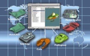
The computer-aided engineering (CAE) method mainly uses computers to analyse, design, and manufacture a product, project, and process. CAE relates to elements of CADD in industry. CAE often work as a recognised umbrella discipline that involves a lot of computer-aided technologies that are not limited to CAD, computer-aided industrial design (CAID), CNC, CAD/CAM, PDM and CIM, plus the Internet and other technologies that collaborate on various projects. Talking about CAE it often focuses on mechanical design and product development automation.

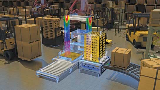
Its most familiar elements of CAE where simulation and solid modelling, analysis, optimisation and testing of mechanical structures. It adds a system that uses digital prototypes. FEA is a kind of process that is often associated with Computer-Aided engineering. 

DESIGN APPLICATION

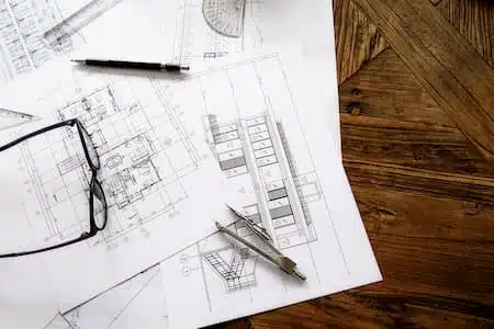
Computer-aided design and drafting (CADD) service companies relate to computer-aided technologies that offer revolutionary tools for engineers and drafters during the engineering design process. CADD enhances design efficiency, creativity, and effectiveness in product development. There are a lot of different forms that accept engineering design processes and integration of CADD within the engineering design process. Get a simplified sample of an engineering design process for a lifting hook.

Computer-Aided Engineering (CAE)

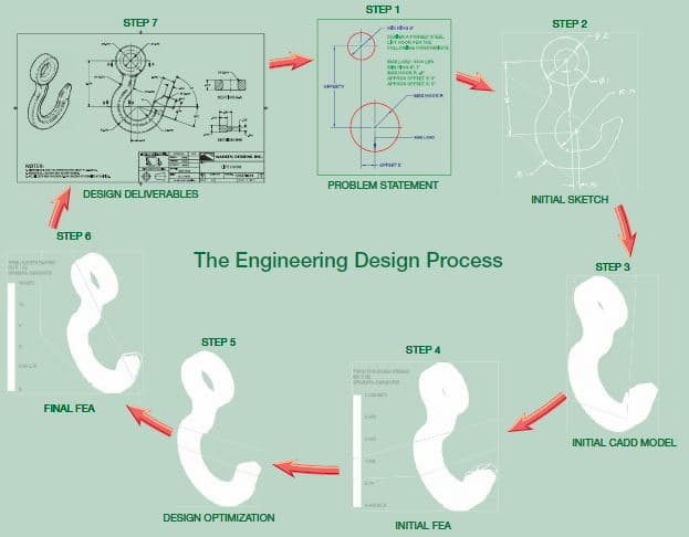
The lifting hook is one best example, and the following information is an introduction to CADD in the engineering design process.

STEP - 1

Step 1 helps to identify the problem along with adding design constraints. It comes with a constraint and a condition adding a specific shape, size, or requirement. It defines a design that satisfies to achieve a successful design. The problem statement describes the requirements and constraints for a forged-steel lift hook that support a 3000-pound load.

STEP - 2

Step 2 offers a sketch of the initial design based on the solution to the problem. The sketch comes with hand-drawn that use CADD as a sketching tool. CADD systems require the creation of a digital sketch as an element of the CADD process. The hand-drawn sketches come with a common practice that especially comes during early design.

STEP - 3

Step 3 can generate an initial three-dimensional computer-aided design (CAD) solid model according to the hand-drawn sketch. Using finite element analysis (FEA) software, you can study the model. Here, FEA applies the finite element method (FEM) to solve mathematical equations related to engineering design problems, including structural and thermal issues.

STEP - 4

Step 4 offers structural stress analysis applied to that lifting hook to simulate a real-world lift.

STEP - 5

Step 5 optimise the design to reduce material with improving shape while maintaining a sufficient working strength. Users can perform design optimisation, adding manual calculations and tests and repeated FEA simulations. It offers an optimised lift hook with CAD solid model.

STEP - 6

Step 6 can re-analyse the model that confirms a solution to the design problem.

STEP - 7

The last step 7 is to use the CAD solid model to prepare two-dimensional (2-D) detail drawings and a digital model format supported by computer-aided manufacturing (CAM) software. The manufacturer mainly uses the supplied data to create the forging equipment necessary to produce the lifting hook.

PROFESSIONAL APPROCHED

A wide variety of jobs are currently available for qualified CADD professionals. Note that the kinds of tasks they may allow is always traditional. In addition to this, they create drawings that are responsible for working in some of the following areas, including:

  • To prepare freehand sketches on the shop floor and convert the sketch with finished CADD drawing.
  • To include Digital image creation and editing.
  • To provide text documents, including proposals, reports, and studies.
  • To incorporate CADD images and drawings into text documents.
  • To conduct research for job proposals, purchasing specifications and feasibility studies.
  • To evaluate and test new software with ease.
  • To train the staff members by using new software or procedures.
  • To collect vendor product information for new projects.
  • To speak on the phone and deal personally with clients, vendors, contractors, and engineers.
  • To check design and drawings by creating accuracy.
  • To research computer equipment and prepare bid specifications for purchase.

Computer Aided Engineering

We often hire employees who possess good tech skills to become good employees. The best jobs that we can find here are those students who developed an excellent understanding of the project planning process and can easily handle any situation.

The process is based on the person’s ability to communicate. It helps to apply solid math skills through trigonometry with exhibiting good problem-solving skills. We know how to use resources and conduct research by getting all data. We can serve general qualifications foundation by adding more specific skills to our study. It includes good working knowledge of drawing layout and construction techniques. Based on applicable standards, it adds a good grasp of CADD software mainly used for creating models and drawings.

In addition, we support you in customising the CADD software that better suits your needs. What is most essential for the prospective drafter to remember. Content applies to the lot of details of an object, situation and procedure. If we are given enough time, then we can find all of the pieces of information required to complete a task.

Here the process refers to a method of doing something. It involves several steps that come with learning a helpful process and making it easier to complete all tasks. We can find all of the content you require and understand an exemplary problem-solving method. It comes with project planning and is used in any situation. We can use the process to make the task easier and determine what content would be beneficial.

There are many more reasons that we strongly recommend you focus on your efforts. We learn and establish good problem-solving habits. Using the skills to locate the content, all we need for any project is to make all aspects of your life productive, efficient, and relaxing. We at Australian Design & Drafting Services company are ready to offer excellent CAD Design and Drafting services. Contact Us to give wings to your project.

What is Engineering Prototyping

What is Engineering Prototyping

PROTOTYPING

A prototype is a functional part model of design; it is used as the basis for continuing the production of the final part or assembly. The terms prototype and model are often used interchangeably. Prototypes are used to determine if a new design works as intended. A prototype is commonly used as part of the product design process to enable engineers and designers to explore design alternatives, determine unknown characteristics in the design, finalize part tolerances, confirm customer interest in the design, verify design performance, coordinate with marketing and sales, and test theories before starting full production of a new product.

A variety of processes can be used to create a prototype. The processes range from creating a digital model to developing a solid physical model of a part directly from a 3-D CAD model data and to fabricating a model using standard manufacturing processes. A company generally contracts with another company that specializes in developing prototypes quickly and accurately. Some companies have their own prototype development departments. A prototype is generally different from the final production part because special processes and materials are used to quickly create a part that can be used to simulate the actual part.
The development phase of the design process is when a fully functioning prototype model is made that operates at the desired quality level. A physical prototype can be machined, molded, or created using rapid prototyping processes. Parts are assembled into the desired product and then tested to determine if the design meets specifi c product requirements such as weight and performance. The design might have to return to the concept phase for reevaluation if some aspects of the design do not perform as intended or manufacturing process appears to be too costly. After the functioning prototype has been built and tested, drawings are created for continuing to full production of the product.

DIGITAL PROTOTYPING

digital prototyping model

A digital prototype is a computer-generated model or original design that has not been released for production. The most common and useful digital prototype is a 3-D solid model. A solid model digital prototype functions much like a physical prototype, is often just as or even more accurate, and can be subjected to real-world analysis and simulation. Digital prototyping is the method of using CAD to help solve engineering design problems and provide digital models for project requirements. Successful digital prototyping offers several ben-efi ts to the engineering design process. It provides companies with a deeper understanding of product function, enables the simulation of product performance as part of a complete system, offers interactive and automatic design optimization based on requirements, and assists other areas of product development and coordination.
Digital prototyping can support all members of a product development team and help communication. Designers, engineers, and manufacturers use digital prototyping to explore ideas and optimize and validate designs quickly. Salespeople and marketers use digital prototyping to demonstrate and describe products. Depending on product requirements and company practices, digital prototyping can reduce or eliminate the need for physical prototypes, which are often expensive and time-consuming to create and test. The figure shows an example of digital prototyping to model, analyze, simulate, and visualize products in a virtual environment.

RAPID PROTOTYPING


rapid prototyping model

Rapid prototyping is a manufacturing process by which a solid physical model of a part is made directly from 3-D CAD model data without any special tooling. An RP model is a physical 3-D model that can be created far more quickly than by using standard manufacturing processes. Examples of RP are stereolithography (SLA) and fused deposition modeling (FDM), or 3-D printing.
Three-dimensional CAD software such as AutoCAD, Autodesk Inventor, NX, Pro/Engineer, and SolidWorks allows you to export an RP fi le from a solid model in the form of a .stl file. A computer using postprocessing software slices the 3-D CAD data into .005–.013 in. thick cross-sectional planes. Each slice or layer is composed of closely spaced lines resembling a honeycomb. The slice is shaped like the cross-section of the part. The cross-sections are sent from the computer to the rapid prototyping machine, which builds the part one layer at a time.

The SLA and FDM processes are similar, using a machine with a vat that contains a photosensitive liquid epoxy plastic and a flat platform or starting base resting just below the surface of the liquid as shown in Figure. A laser-controlled with bi-directional motors is positioned above the vat and perpendicular to the surface of the polymer. The first layer is bonded to the platform by the heat of a thin laser beam that traces the lines of the layer onto the surface of the liquid polymer. When the first layer is completed, the platform has lowered the thickness of one layer. Additional layers are bonded on top of the first in the same manner, according to the shape of their respective cross-sections. This process is repeated until the prototype part is complete.
Another type of rapid prototyping called solid object 3-D printing uses an approach similar to inkjet printing. During the build process, a print head with a model and support print tip create the model by dispensing a thermoplastic material in layers.

The printer can be networked to any CAD workstation and operates with the push of a few buttons as shown in Figure.
Rapid prototyping has revolutionized product design and manufacture. The development of physical models can be accomplished in significantly less time when compared to traditional machining processes. Changes to a part can be made on the 3-D CAD model and then sent to the RP equipment for quick reproduction. Engineers can use these models for design verification, sales presentations, investment casting, tooling, and other manufacturing functions. In addition, medical imaging, CAD, and RP have made it possible to quickly develop medical models such as replacement teeth and for medical research.

RAPID INJECTION MOLDING PROTOTYPING

rapid injection molding prototyping by rapid injection molding rapid injection molding protoryping

Rapid injection molding is an automated process of designing and manufacturing molds based on customer-supplied 3-D CAD part models. Because of this automation, lead time for the initial parts is cut to one-third of conventional methods. Cost-saving varies with the number of parts being produced, but rapid injection molding can also have a substantial cost advantage in runs of up to thousands of parts. Rapid injection molding produces quality molds using advanced aluminium alloys and precise, high-speed CNC machining. Parts can be molded in almost any engineering-grade resin. The figure shows the 3-D CAD part model, the injection molded part in the mold, and the resulting rapid injection molded part.

SUBTRACTIVE RAPID PROTOTYPING

Subtractive Rapid Pr ototyping

Subtractive Rapid

 Rapid Prototyping Subtractive

CNC machining of parts has been around for decades, but the use has typically not been applied to short lead-time prototype development. Subtractive rapid prototyping uses proprietary software running on large-scale computers to translate a 3-D CAD design into instructions for high-speed CNC milling equipment. The result is the manufacturing of small quantities of functional parts very fast, typically within one to three business days. A variety of materials, including plastics and metal, can be used with sub-tractive rapid prototyping. The figure shows the 3-D CAD part model, the CNC machining process, and the machined part.

CONVENTIONAL MACHINING PROTOTYPING

Some companies have a machine shop combined with the research-and-development (R&D) department. The purpose of the machine shop is to create prototypes for engineering designs. Drafters generally work with engineers and highly skilled machinists to create design drawings that are provided to the machine shop for the prototype machining. This practice generally takes longer than the previously described practices, but the resulting parts can be used to assemble a working prototype of the product for testing.

Australian Design & Drafting Services provide excellent service for CAD Design and  Drafting. Contact Us for more info

what is engineering Drawing

WHAT IS THE ENGINEERING DRAWING

Engineering drawing is a common language that describes the process of creating drawings for engineering and architectural application. The engineering drawings work the best and accept standards and format.

It offers an efficient way to communicate and use specific data with adding design intent. The Engineering drawings do not require work and interpret of others' drawings. It comes with decorative drawings along with using artistic paintings. Using a successful engineering drawing, the user can describe a specific item that the drawing viewer understands without misinterpretation.

One can talk about the term engineering drawing, known for its Drafting, mechanical drawing, mechanical Drafting, engineering drafting, technical Drafting and technical drawing. The Drafting comes with a different graphic language that uses lines, symbols, and other notes to describe objects for an industry like manufacturing or construction. There are technical disciplines that use Drafting, covering civil, architecture, electrical engineering, electronics, piping, manufacturing, and structural engineering.

The term mechanical drafting comes with alternate meanings. The manufacturing industry comes with mechanical Drafting, where the name is derived from mechanisms. The construction industry uses mechanical Drafting in terms of drafting heating, ventilating, and air-conditioning (HVAC) systems. It comes with a mechanical portion of an architectural project.

Whereas if we talk about manual Drafting, it’s a term that describes traditional drafting practice, including pencil or ink onto a medium. It covers paper or polyester film, which supports drafting instruments and equipment. Computer-aided Drafting (CAD) has taken the place of manual Drafting, where the CAD uses computers for drafting. CAD also refers to computer-aided design when computers are used to design.

ENGINEERING DRAWING

Engineering drawings add various concepts that cover instructions, engineering requirements, and proposals. It comes with multiple people and includes different individuals involved with a project. An engineering drawing comes with a complete set of engineering designs that offer data needed to manufacture an item or product. It includes machine parts, consumer products and many more structures.

ENGINEERING DRAWING

The drawing study covers medical instruments that completely describe all geometric features' location and size. Later, it identifies the characteristics of the part. It mainly uses the material along with manufacturing precision. Also, the medical instrument company uses the drawing to share the document design, which intends to be a part of manufacturing. Let’s say how difficult it can be to understand the engineering drawing.


ENGINEERING DRAWING AUSTRALIA

Actually, the engineering drawing comes with an architectural drawing that is mainly used for home re-modelling projects. The drawing uses one sheet in a set of communication with architectural style, size, and location with building features and taking care of the construction methods and materials.

The drawing offers sheets that communicate architectural style, the size and location of building features, and construction methods. The drawings are set to obtain to pay for construction, make permits and legally begin construction. It offers accurate cost estimates that bring impossible and impractical construction without engineering drawings.

Computers In Design and Drafting

The computers offer revolutionised business along with adding industry process. It covers design and drafting practices with ease. Computer-aided design and drafting (CADD) is a process that uses a computer with CADD software for design and drafting applications. Also, the software is a program that enables a computer to perform specific functions and accomplish a task. Talking CAD is the acronym for computer-aided design, referred to as computer-aided Drafting.

Computer-aided design and computer-aided Drafting offer specific aspects of the CADD process. It mainly uses CADD for the design and drafting process to get accurate and faster CAD design. Several industries mostly use engineering and architecture to get a better outcome. Most engineering industries and educational institutions use manual drafting practices that evolved to CADD.

Whereas CADD allows drafters and designers to produce accurate drawings with neat and matched industry standards. CADD makes architectural drawings with artistic flair lettering and line styles, including a matched appearance with the finest handwork available. In addition to this, CADD drawings come consistently from one person or company to the next. It supports enhancing the ability of designers and drafters, adding creativity to it. It uses new tools such as solid modelling, animation, and virtual reality.

We are an excellent Australian Design & Drafting Service company that provides the best CAD Design and Drafting. Contact Us to get more information.


difference between IGES and STEP Files

What is difference between IGES and STEP Files?

What is difference between IGES and STEP Files?

IGES and STEPFILES both are "neutral file formats". They are compatible with using different 3D packages. The IGES (Initial Graphics Exchange Specification) is the oldest developed in the mid '70s used to solve compatibility issues between different software packages. Let’s discuss about each of them in brief:

STEP (Standard for the Exchange of Product data) created in the '80s and uses ISO as an improvement on IGES. It’s most widespread format in IGES and can contain basic 2D or 3D data. It is more versatile and contains additional data using material information and tolerances.

For most design engineers, the scenario looks familiar: Let’s say, Person 1, the lead designer of company X, require to send a CAD model to Person 2, the design engineer for company Y. Person 1 designed the part and Person 2 works in Pro Engineer. Person 1’s file can’t be opened in person 2’s software, therefore, it become simple to transfer a part file and become a problem.

The issue of non-interchangeable proprietary file formats for CAD data have work for decades. The software companies promote the use of modelling packages and ensure that only their package can open a file that created in their software. Unfortunately, all major 3D modelling software company can communicate between them is an issue.

Also, a solution exists in the form of neutral file formats where one canpass between different modelling software packages. One can use a neutral file format to pass CAD mode and then open it and work with it as required. The most common variants of all neutral file formats are the IGES and STEP formats. User recognise these formats by understanding the file name that ends with. iges, .igs, .stp, or .step.

THE HISTORY OF NEUTRAL FILE FORMATS

Talking about mid-seventies, the United States government realised that it had an issue. With using the unique proprietary CAD programs adds different contractors, millions of dollars and countless hours in it. They wasted the tedious process for sharing and converting data between all the systems. One can imagine how many times the scenario has played out on a large project such as an aircraft carrier or missile delivery system using hundreds of suppliers. Moving on with Air Force launched project in conjunction with Boeing.

There are large industry partners that create a neutral file format. The result was IGES (Initial Graphics Exchange Specification).It comes with flexible file format that can code drawing, 3d geometry, and add critical CAD data in a format can be shared between major CAD systems. The US Department of Defence require IGES format that is used for all weapons that has been adopted in other industries as well.

STEP (Standard for the Exchange of Product data) was created in the eighties along with an improvement on the IGES standard by ISO (the International Standards Organization). The goal creates global standard based on awide range of CAD-related data types. It adds complexity that undertake years of development and still continuously upgrade it. It offers largest ISO’s standards.

DIFFERENCE BETWEEN IGES AND STEP

IGES uses widespread standard, that supports all major CAD systems worldwide.

An IGES file contains basic CAD information including 2D and 3D geometry such as surfaces, curves, and wireframes.

  • It comes with presentation elements including drafting elements like lines and annotations.
  • It offers electronic and pipe schematic elements along with finite element modelling.
  • It comes with language and product definition data.

STEP comes with newer standard whereas IGES is not widespread. There are major CAD programs that is well-recognise as STEP and it’s steadily grown as their standard improves.

STEP documents contain the same product definition information as IGES, with the following additions such as Topology, Tolerances, Material properties and various other complex product data.

PRACTICAL CONSIDERATIONS

In several cases there are solid models or drawings shared with either file format that work fine. It comes with compatibility that is safest to start with IGES. It comes in most common format that is most likely to work by receiving party’s software. However, a designer considers the data to be shared with ease. If the file contains more product definition (for example, geometric dimensioning and tolerancing data, material properties, etc), then STEP would be a better choice.

It is not uncommon for supplier to trouble work with one format. Whereas it requests its alternative by depending on your software. It became familiar in most situations. We are the best Australian Design & Drafting Services company to provide excellent CAD conversions for IGES and STEP file to native file format. Contact Us to get more information.

Electrical Design Evolution

The New Dimension in Electrical Design Evolution or Revolution?

how electrical engineers moved from paper sketches to 3d

Hi Folks! Its chilling winter here in Australia, so let's have some warms up from electrical design and drafting news..

Over the past 260 years, the way we light our homes and power our businesses has changed dramatically. We’ve traded candles for light bulbs, abandoned the abacus for super computers, and swapped selenium wafers for energy-efficient solar panels. We now have a generation of products that are connected to the internet to improve the quality of our lives–think smart appliances, fitness monitors, and intelligent trash cans.  These innovations reflect advances in scientific thinking—and advances in the way engineers design increasingly complex electrical design systems.

1752: Lightning in a … Kite?electrical design

Benjamin Franklin was an inventor, writer and statesman, but he was also an engineer who developed electrical systems using hand sketches. His best-known feat? Verifying that lightning is actually electricity.

In June 1752, history says that Benjamin Franklin sent a key attached to a homemade kite into the air. “As soon as any of the thunder clouds come over the kite,” he wrote, “the pointed wire will draw the electric fire from them, and the kite, with all the twine, will be electrified.” While there’s a good chance Franklin made up the tale, his theory was ”electrifying.”

1879: A Little Menlo Park Magic

Picking up where Franklin left off, Thomas Alva Edison (aka the Wizard of Menlo Park) held more than 1,000 patents. In 1879, he introduced the electric light bulb. It lasted longer than previous models and employed a carbonized cotton thread filament.

Edison made a host of other contributions to electrical design, including the system of power stations now called General Electric, and schematics continued to be the planning tool of choice.

Although a true technological genius, Edison wasn’t all butterflies and rainbows— he electrocuted puppies, a horse, and an elephant in an attempt to label alternating

current (AC) power as dangerous. He lost this campaign and Nikola Tesla’s AC induction motor won, mechanizing factory work and powering household solidworks electrical designappliances.

But that (admittedly creepy) anecdote hardly tells the full story of Edison’s life. He went on to improve life for generations of Americans with the phonograph, motion pictures, the storage battery, and more.

1907: Vacuum Tubes

Throughout the 20th century, electrical engineers used schematics to represent increasingly complicated systems for radio, medical devices, and computers. In 1907, Lee De Forest patented the audion, which enabled clearly audible sounds such as a human voice to be relayed and amplified using a three-electrode vacuum tube–the world’s first triode.

1929: Machine Packs Serious Voltage

Wiring diagrams based on physical connections entered the electrical engineering vocabulary in 1929, when Alabama native Robert Jemison Van de Graaff built the first working model of an electrostatic accelerator.

Its purpose: accelerate particles, break apart atomic nuclei, and unlock

the secrets of individual atoms. Van de Graaff’s invention is used widely in science classrooms and paved the way for future electrical research.

1947: Transistor Transition

Schematics advanced yet again when electrical engineers began creating them based on logical connections. A major breakthrough occurred in 1947 when John

Bardeen, Walter Brattain, and William Shockley collaborated to demonstrate the transistor— which amplifies or switches electrical signals—at Bell Laboratories. The semiconductor, which paired two gold contacts and a germanium crystal, represented an upgrade from cumbersome vacuum tubes.

1977: We’ve Gone Digital!

By the late 1970s, functions such as placement and routing became available in automatic physicalElectrical design Drawings

electronic design automation (EDA)— marking the birth of the digital schematic. Bell Labs, along with companies such as IBM and RCA, held advanced tools that operated on mainframes or 8-bit minicomputers. In 1977, super minis provided massive amounts of memory for designs.

Today: Entering a New Dimension

For decades, companies have developed products that feature both mechanical and electrical components. The traditional product development process for an electromechanical product has created long design cycles due to sequential electrical and mechanical design, as well as the discontinuities which occur when different groups use different names for common elements.

There are challenges in keeping the Bill of Materials (BOM) accurate through the use of so many spreadsheets. Often, once the electrical design piece has been completed,

it is then handed off to the mechanical design team. After they complete their part of the design, the entertaining part happens when it comes to figuring out how the electrical pieces fit into the product. A physical prototype is built at this point and

the designers get out a ball of string or a measuring tape to figure out how the wiring will fit. Given all the powerful software design tools we have, it’s ironic that we have fallen back to low-tech ways of integrating the electrical and mechanical pieces of the design. As you might expect, this method is prone to introducing lots of errors

and delays into the production process, product documentation, and BOM.

Things have evolved a bit over the last couple years. Electrical schematics entered the third dimension in 2012, when SOLIDWORKS introduced powerful and affordable 3D electrical CAD software for Windows, merging the logical connections championed by Benjamin Franklin with the modern day need to build 3D physical connections.

Using SOLIDWORKS® Electrical software, you can easily design electrical schematics and transform the logical schematics into 3D physical models which integrate into the overall design. SOLIDWORKS Electrical 3D™ integrates with SOLIDWORKS 3D CAD modeling software to enable bi-directional and real-time integration of electrical components within the 3D model maintaining design synchronization and an accurate BOM. In this way, the entire engineering team can collaboratively work on a project concurrently, which not only produces a more integrated design; it can also lower project costs, and shorten time to market.

New Dimension in Electrical Design Evolution

Another benefit of the integrated SOLIDWORKS solution for electro-mechanical design is the ability to analyze or simulate the operation of the entire model against real-world conditions, such as thermal stress or physical vibration–all without having to build a physical prototype. This seems like “common-sense” (which even a man like Benjamin Franklin would appreciate if he were alive today).

From light bulbs to intelligent trash cans—and from handwritten notes on paper napkins to 3D modeling—one thing is clear: electrical design has entered the next dimension.

Australian Design and Drafting services provides excellent quality Electrical Design and drafting services around Australia in major cities like Brisbane, Sydney, Melbourne, Perth, Gold Coast, Newcastle etc.. Feel free to contact us for any requirements.


solidworks design drafting brisbane sydney

What You should know about Solidworks and its History?

In the following article, I will describe you in short sentences the genesis of SOLIDWORKS. How did it happen and why SOLIDWORKS until today has been so successful.

In December 1993, Mr. Jon Deer Tick founded together with a team of engineers SOLIDWORKS in Waltham Massachusetts / USA.His goal was to create a 3D CAD software (computer-aided design), therefore to develop a computerized program that volume body based modeling and to create technical drawings digitally. In addition, this software should be as user-friendly and do not require costly hardware.

Deer Tick opted for the Windows platform, in the very successful release of Windows 95. He and his team developed and programmed over a year and came up with the "initial release" 1995th first edition.

The friendly interface and intuitive handling of the parametric features made SOLIDWORKS quickly became popular. SOLIDWORKS was Distributed by certified resellers, offered in 1996 for the small machine builders in Germany at affordable prices and became the German success story.

In 1997, the French software company Dassault Systèmes took notice of SOLIDWORKS success stories and bought it for 310 million US dollars. There were initial doubts by SOLIDWORKS users, whether Dassault SOLIDWORKS would be implemented in the CAD program Catia or would give up entirely, but the Dassault Systèmes quickly realized the potential of SOLIDWORKS and focused on its further development.

Since SOLIDWORKS is continuously developed and expanded modularly. There are a variety of additional applications and industry-supporting functions. Such as the Sheet metal features or the weldment features.

Currently SOLIDWORKS is worldwide, more than 3,073,600 licenses in 23,400 locations in 80 countries.

Various SOLIDWORKS product range Available

3D CAD Packages

SOLIDWORKS Premium

SOLIDWORKS Premium is a comprehensive 3D design solution that adds powerful simulation and design validation to the capabilities of SOLIDWORKS Professional, as well as ECAD/MCAD collaboration, reverse engineering, and advanced wire and pipe routing functionality.

SOLIDWORKS Professional

SOLIDWORKS Professional builds on the capabilities of SOLIDWORKS Standard to increase design productivity, with file management tools, advanced photorealistic rendering, automated cost estimation, eDrawings® Professional collaboration capabilities, automated design and drawing checking, and a sophisticated components and parts library.

SOLIDWORKS Standard

Get up to speed quickly with SOLIDWORKS Standard and unlock the benefits of this powerful 3D design solution for rapid creation of parts, assemblies, and 2D drawings. Application-specific tools for sheet metal, weldments, surfacing, and mold tool and die make it easy to deliver best-in-class designs.

SOLIDWORKS Visualization Products

SOLIDWORKS Visualize Professional

An extensive tool set to easily create images, animations, and interactive content.

SOLIDWORKS Visualize Standard

The fastest and easiest way to photo-quality images for anyone that needs to take "photos" of their 3D data.

SOLIDWORKS Simulation Premium

Ensure product robustness using the range of powerful structural simulation capabilities in SOLIDWORKS Simulation Premium. It goes beyond SOLIDWORKS Simulation Professional and includes additional tools for simulating nonlinear and dynamic response, dynamic loading, and composite materials.

SOLIDWORKS Simulation Packages

SOLIDWORKS Flow Simulation

Efficiently simulate fluid flow, heat transfer, and fluid forces critical to your design's success with SOLIDWORKS Flow Simulation. Driven by engineering goals, SOLIDWORKS Flow Simulation takes the complexity out of computational fluid dynamics (CFD) and enables Product Engineers to use CFD insights for making their technical decisions in a concurrent engineering approach.

SOLIDWORKS Plastics

Predict and avoid manufacturing defects during the earliest stages of plastics part and injection mold design using SOLIDWORKS Plastics simulation software. Companies that design plastic parts or molds can improve quality, eliminate costly mold rework, and decrease time-to-market.

SOLIDWORKS Sustainability

Conduct life cycle assessment (LCA) on parts or assemblies directly within the SOLIDWORKS 3D design window. Search for comparable materials, see in real time how they affect environmental impact, and easily document your findings.

Product Data Management Packages

SOLIDWORKS PDM Professional

SOLIDWORKS PDM Professional is a full-featured data management solution for organizations large and small. SOLIDWORKS PDM Professional helps your team more easily find and repurpose files, parts, and drawings; share design information; automate workflows and ensure manufacturing always has the right version.

SOLIDWORKS PDM Standard

SOLIDWORKS PDM Standard is a new data management solution for smaller workgroup environments in one geographic location. Included with SOLIDWORKS Professional and Premium, SOLIDWORKS PDM Standard helps SOLIDWORKS and DraftSight users easily and efficiently organize and manage their data.  SOLIDWORKS PDM Standard can be easily upgraded to SOLIDWORKS PDM Professional if and when needs change.

EXALEAD OnePart

EXALEAD OnePart helps engineers and designers decide between design creation or design reuse in just one min. EXALEAD OnePart is a business discovery application that accelerates reuse of parts, designs, specifications, standards, test results and related data for engineering, manufacturing, and procurement activities. Leveraging the proven web semantics, analytics, and big data management technologies of EXALEAD CloudView™, OnePart locates information from multiple sources and makes it available instantly.

Technical Communication Packages

SOLIDWORKS® MBD

SOLIDWORKS MBD helps define, organize, and publish 3D Product Manufacturing Information (PMI) including 3D model data in industry-standard file formats. It guides the manufacturing process directly in 3D, which helps streamline production, cut cycle time, reduce errors, and support industry standards.

SOLIDWORKS Inspection

SOLIDWORKS® Inspection helps you streamline the creation of inspection documents by leveraging your existing 2D legacy data, regardless of whether files are SOLIDWORKS, PDFs, or TIFFs.

SOLIDWORKS Inspection software automates the creation of ballooned inspection drawings and inspection sheets for First Article Inspection (FAI) and in process inspections. Save time and virtually eliminate errors by speeding up this repetitive manual process.

SOLIDWORKS Composer

SOLIDWORKS Composer™ enables you to easily repurpose existing 3D design data to rapidly create and update high quality graphical assets that are fully associated with your 3D design.


SOLIDWORKS Composer users can routinely create technical documentation parallel with product development, simplifying their process and accelerating time-to-market. Manufacturing Engineer Rob Schwartz of ARENS Controls, LLC relates that for one of their products “I had the instructions done before the first parts arrived on the dock. Not only was I freed from having to wait for parts or assemblies, I was able to put together better content in a fraction of the usual time.”

SOLIDWORKS Electrical Solutions

SOLIDWORKS Electrical solutions are integral parts of the SOLIDWORKS design and simulation portfolio that help Design Engineers reduce the risk inherent in innovation and get their products to market faster with less physical prototyping to decrease costs. With a consistent, powerful, intuitive set of electrical design capabilities, all fully integrated with the SOLIDWORKS solution portfolio, designers can establish an integrated design early in the design process and avoid costly design rework.

SOLIDWORKS PCB Powered By Altium

A professional PCB design tool capable of meeting the demands of today’s products, which allows you to develop the most efficient schematics for your board layouts. Integration of PCB design seamlessly with SOLIDWORKS CAD, with a managed ECO change process and distinct workflows to keep you at your most productive.

SOLIDWORKS Electrical Schematic Standard

A powerful, stress-free, easy-to-use single user schematic design tool helps rapid development of embedded electrical systems for equipment and other products. Built-in and web-enabled libraries of symbols and manufacturer part information provide common re-usable materials optimizing design re-use. You can streamline and simplify an array of tedious design tasks, from terminal block to contact cross reference assignments, with our automated design and management tools.

SOLIDWORKS Electrical Schematic Professional

A powerful, stress-free, easy-to-use suite of collaborative schematic design tools drives rapid development of embedded electrical systems for equipment and other products. Built-in and web-enabled libraries of symbols, manufacturer part information, and 3D component models provide common re-usable materials optimizing design re-use. You can streamline and simplify an array of tedious design tasks, from PLC and terminal block to contact cross reference assignments, with our automated design and management tools.

SOLIDWORKS Electrical 3D

Integrate electrical schematic design data with the SOLIDWORKS 3D model of a machine or other product—bidirectionally and in real time. SOLIDWORKS Electrical 3D enables you to place electrical components and use advanced SOLIDWORKS routing technology to automatically interconnect electrical design elements within the 3D model. Determine optimal lengths for wires, cables, and harnesses, all while maintaining design and bill of materials (BOM) synchronization between electrical and mechanical designs.

SOLIDWORKS Electrical Professional

Combine the electrical schematic functionality of SOLIDWORKS Electrical Schematic with the 3D modeling capabilities of SOLIDWORKS Electrical 3D and do it all in one powerful, easy-to-use package. SOLIDWORKS Electrical Professional is ideally suited for the user that supports both the electrical and mechanical design integration.

CircuitWorks™

Share data between electrical CAD (ECAD) and mechanical CAD (MCAD) designers using the CircuitWorks™ tool in SOLIDWORKS 3D CAD software. Circuitworks™ enables users to share, compare, update, and track electrical design data so users can more quickly resolve electrical-mechanical integration problems.

Australian Design and Drafting services provides excellent quality solidworks services around Australia in major cities like Brisbane,Sydney,Melbourne,Perth,GoldCoast,Newcastle etc..Feel free to contact us for any requirements related design and drafting till then Stay cool,stay stronger..


3d Designer & Drafter

What are the Main fundamental Issues for 3d Designer/Drafter?

Designers and drafters encountered a few fundamental issues during the design process. It addresses the process that comes with 3D designer and drafter with creating a separate drawing production regardless of the manufacturing process. There have been several delays seen in the process. For example, if a drawing comes with an incorrect dimension, it offers a production drawing that can rework with time and massively disrupted.

We have a team of 3D designer drafters that do the manufacturing work and integrate the complete product development process. It adds lots of intelligent 3D design and drafting software available. It makes sure that your design and manufacturing work is mainly used daily. There is much intelligent 3d design and drafting software available for producing accurate manufacturing drawings. Additionally, if we talk about design and drafting company today, it helps to resolve all problems with ease.

We offer two essential questions during the design process

1. IS THIS PRODUCT FINANCIALLY FEASIBLE?

The total cost to produce a product mainly influence a variety of factors. It primarily uses material and labour costs that seemingly offer small changes and significantly impact the overall cost structure. As a leading Australian design and drafting company, our costing ensure that no cost-related surprises come to you when your model goes into production.

Our team allows 3d designers/drafters to act in a better way. Our project managers and the Engineers pursue new product development that gives a clear cost perspective regarding compliance and the pre-calculated structures. It monitors the impact of changes as it is transparent and clear.

Additionally, it comes with advantages like cost-effective product costing. It comes with the ability to work with both original models and drawings. It uses 3D CAD programs or neutral formats like IGES or STEP. Here, the user can define different materials and make changes to drawing or relocate the manufacturer’s place. The model changes are displayed immediately in cost per piece.

2. CAN THIS PRODUCT BE MANUFACTURED?

Australian design and drafting company support 3d designer/drafter and mould makers and respect the feasibility of your products. In the development process, there are complicated shape models that change regularly. The export process and the data repairing have high error probabilities and inaccuracies.

There are a few reasons, like when mould makers wait until the final design of a product is established and develop the final form. The cost of valuable production time is also well-noted. We at Australian Design and Drafting are early to make form. In addition to this, we offer a correct form of geometry that covers sketches, audit and control of thickness. For example, Plastics can perform a detailed filling analysis by determining the optimum position of the injection points.

The team ensures the proper filling pattern of the component, tracks the form weld lines and adds necessary points.3d designer/drafter can have a complete product development process and ensure effective communication between design and production during the entire development process. Australian Design and Drafting Services provides quality and cost-effective 3d design and drafting services across Australia. If you have any queries or inquiries regarding 3D modelling, Drop us an email at info@astcad.com.au or call us 1800 287 223 (Toll-Free) Australia Wide.

Autodesk Inventor Intellectual Property

How to Protect Design Intellectual Property with Autodesk Inventor?

Several companies in the engineering and manufacturing field use Autodesk inventors in their process, including sensitive and confidential data. Today, there are millions of files coming and going in cyberspace in this modern business world. Companies should protect their Intellectual Property (IP).

It’s essential when manufacturing a product. As it takes countless hours of engineers’ time, not to mention a company’s reputation if a “knockoff “product adds a lesser classic hit to the market. We have found that as industries work, we see the need to work with Architects or architectural design firms with bringing solid mechanical models.

There are boilers or mezzanines into Revit that represent placement, shape and size. Regardless of the situation, we would like to keep all intellectual property safe. This is why Autodesk worked so hard to prevent this with Autodesk Inventor simplification. It allows the user to create a simple version for the consumer by providing critical design information. We help you learn this crucial tool by using it in a great way.

THE FULL MODEL

Below is the section that creates internal and external items that provide the customer with the model for planning purposes in Autodesk. They require few connection points. One can do it in a few ways, and the first is to create the shell of the original model as its single part. Another one is to create basic shapes to represent the model.

Autodesk Inventor

COMPONENTS INCLUDED

The first step is to protect your intellectual property from simplifying the tab. It helps to choose the components that include what we do with the Include Components command.

Inventor Intellectual Property

After selection cover

The components come with a mini toolbar. It allows you to choose various options from the dropdown menu. The first drop down comes with an opportunity to view all components. It included internal and external constituents. We find it most helpful to switch between the three viewing options while making my selections. It allows reviewing any missing parts which should not be included. As shown in the screen, it captures below what each option does. The dropdown option mainly refers to choosing part, component, or other parent priority. After choosing your options and selecting what needs to be included, click the checkmark to finish this part of the process.

autodesk Inventor Intellectual Property

VIEW-MASTER

Once you finish including components, you’ll notice that you can no longer see any items that aren’t included. If we look at our View-Master, the command automatically creates a view called Simple View 1. Get the right click on this view in the browser with editing the selections.

Intellectual Property Inventor

CREATE SIMPLIFIEDPART

The third step is to select “Simplified Part”. This launches a new dialogue box and the standard new part creation options. It primarily uses a file that saves location and name. It includes options for what type of part you create and combining style buttons. The options are:

  • A single solid body that seems between faces merged.
  • It helps to maintain the body separately.
  • It primarily uses single solid body with seems between faces maintained
  • It’s used for our purposes and now see the BIM tab opened for further simplification.

Note: It uses simple View 1 along with the current view. It always helps to create a Simple Folder for all simplified parts.

Autodesk Inventor

FURTHER SIMPLIFICATION AND BIM TAB

At this point, the model is simplified with a great deal. One can simplify it more using the Simplify section of the BIM Tab. We will include the other half of the BIM Tab in the following paper.

Inventor Autodesk Intellectual Property

REMOVE DETAILS

The first look removes details commands that recognize fillets and chamfers and custom selected faces. It utilizes a mini toolbar for any options. It looks at the mini toolbar. We provide a few options for items to remove. The All Faces Selectable allows selecting faces. We added Fillet and Chamfer selection box set by default. Our last Option is Auto Select. Use the screen that captures below with understanding how these options work.

Intellectual Property Inventor

FILL VOIDS

The second option here covers simplification with Fill Voids. It uses a prospect that fills holes and spaces with surface patches. This leaves a smooth surface that selects besides the auto Select by select loop, select edge, select face and more.

Check below to view how these tools function.

Intellectual Property Inventor

DEFINE ENVELOPES

The third option simplifies the parts further with the Defined Envelopes option. The option replaces a part or object used in the solid object form of a cylinder or box. Our choices on this toolbar are used for the bounding box and the bounding cylinder for the first button. Join or add new solid in the second button, and our selection methods faces are solid. See below for examples.

Autodesk Inventor

If you all need any help regarding the design and drafting services, please don’t hesitate to connect with us. We are the best leading Australian Design and Drafting Services company in Australia. Call us 1800 287 223 (Toll-Free) Australia Wide.

CAD drafting software autocad,catia,solidworks,microstation

Best CAD Drafting Software

We at the Australian design and drafting company use excellent computer-aided drafting tools. The CAD Drafting wiped out and replaced almost all traditional hand drafting techniques. They are used in several industries, especially in mechanical engineering and design. They are faster to conduct, and computer-aided drawings are used to modify the vulnerable to physical damage.

It comes with the sheer advantages, where the CAD drafting has become the essential standard for mechanical engineers. It formulates comprehensive strategies that add mechanical components to products and demonstrate a visual illustration.

Users need to know how to construct it as it allows flawless and effective functioning. To cash the ever-rising popularity of the drafting techniques, one needs to use global brands that stepped forward and dished out their sophisticated CAD drafting software. Eventually, it makes it more difficult for customers to make up their minds and choose a program.

Here, we will have a closer look at the three best CAD drafting software around in the market. It covers:

  • AutoCAD
  • MicroStation
  • CATIA 

WHAT MAKES AUTOCAD THE BEST CAD DRAFTING SOFTWARE

AutoCAD has made its way into the market by providing excellent CAD Drawing Software almost three decades back, in 1982. Ever since, it’s been on the top that continuously rules the charts. It offers the best utility for documenting your design ideas and comes with a wide range of features and tools. It adds the whole drafting process becomes more like a walk in the park.

The program used allows efficient editing and repurposing of the drafting process. It evaluates the available design options that will enable existing geometries to improvise using easy-to-remember and easy-to-execute commands. Another highlighting feature of this program comes with a key advantage that makes AutoCAD the best CAD drafting software today. It allows driving efficient design documentation and other essential drafting practices. Efficient content reuse is possible as one can either work on windows or Mac platforms. This allows you to customize your work environment. 

HOW CATIA MADE TO THE LIST OF BEST CAD DRAFTING SOFTWARE

CATIA – Computer-Aided Three-dimensional Interactive Application adds up in the three best CAD drafting software lists. It is a multi-platform suite that is written in the C++ language. Even though the first stable was released in March 2011. It’s the origin of CATIA that traced back to 1977.

CATIA comes with a leading product development solution for manufacturing organizations across industries. This covers automotive, aerospace, electrical, industrial machinery, electronics, plant design, shipbuilding, etc. A few of its highlighted aspects include:

Real-time drafting adds adequate security that comes with integrity and traceability.

It has an accessible drafting context of using large products or configurations. Later, it supports multi-disciplinary collaboration on diverse systems and various products. Additionally, it comes with cross-platform support.

THREE DECADES OF EXCELLENCE MAKE MICROSTATION THE BEST TOOL

MicroStation is a computer-aided design software suite that allows 2D and 3D design and drafting. It is a popular product in multiple industries and has been available since the 1980s. Earlier, most of us were focusing on Apple’s Mac platform. The recent releases of the CAD Drawing tool were exclusively aimed at Windows OS.

The DGN comes in native format, where the MicroStation extends its compatibility into other forms such as DXF, DWG, AVI, BMP, JPEG, PDF, VRML etc. It comes with the best CAD drafting software, where the Micro-station facilitates includes:

  • Extensive format compatibility includes DGN, DXF, PDF, 3DS, IGES, IFC, and CGM.
  • Real-time sharing of live design data
  • The ability to render and viewpoint clouds

If you’re looking for help regarding design and drafting services, then contact us. We are Australian Design and Drafting Services; call us at 1800 287 223 (Toll-Free) Australia Wide.

Google Sketchup

Can Google Sketchup replace AutoCAD?

If we talk about AutoCAD, then it’s well-suited for 2D and 3D mechanical, architectural design engineering, or civil. Sketchup also works excellent with 3D modelling and basic rendering objects. If you most spend time using designing tools, then Google Sketchup works best for you.

Does Sketchup work similarly to AutoCAD?

Sketchup and AutoCAD can be used in architecture and product design. It is based on precise 2D drawings and adds a great set of tools. Additionally, Sketchup is known for its easy to learn and user-friendly tool. It does manage architectural projects very well. Google Sketchup does offer minimized look and feel at first glance. It seems to lack the horsepower modelling software with ease. However, it’s like an old-school muscle car that’s been supercharged with real power. Though the user interface and capabilities come with Sketchup, it might give AutoCAD a run for its money. Additionally, two large limitations need to be overcome before Sketchup take on the big dogs. 

Let’s understand a few limitations of how Google Sketchup can replace AutoCAD.

Limitation: Compatibility

Sketchup is wrestling with a few debilitating bugs. The textures imported into Maya 6.0 or 6.5 tend to reverse themselves. The mesh system can transfer the Sketchup with recreating on the receiving machine. If you thinking about exporting to someplace and forget about it, this can be listed in the bug. These issues will need to be addressed and remedied before Sketchup gains serious market traction against AutoCAD.

Limitation: Naming Conventions

It comes with more limitations where the forced truncation of file names for Google Sketchup textures poses a problem for users. It commands large, complex, or sophisticated projects requiring specific naming conventions.

The antiquated 8.3 DOS character maximums limit Google Sketchup. Therefore, the file names must be shortened to eight characters or less. It poses a significant problem for high-end designers that juggle hundreds or thousands of textures. It swapped in and out quickly and easily. It is far less intuitive with Sketchup, which would be with AutoCAD with naming conventions.

Advantage: Free Models

Google Sketchup hooks up to 3D Warehouse. It contains a massive assortment of pre-designed models of all shapes and sizes with hundreds of thousands of them. The AutoCAD typically ships about 4,000 pre-designed model templates. The users can easily access few thousand or more AutoCAD user sites. The availability of pre-designed models from Sketchup is jaw-dropping.

When Google correct the compatibility and naming convention problems with Sketchup, AutoCAD has a tough and determined competitor. Until then, serious designers stick with the big dogs. If you require any support regarding design and drafting services, don’t hesitate to contact us at Australian Design and Drafting Services or call us at 1800 287 223 (Toll-Free) Australia Wide.

you spend any time at all using designing tools or rendering and model software, whether professionally or as a hobby in your free time, you’ve no doubt heard of Google Sketchup by now.

A fast, free, easy to learn designing tool that competes with AutoCAD (or does it?), Google Sketchup offers an extremely friendly user interface and a minimized look and feel that might, at first glance, seem to lack the horsepower of more well-known modeling software. However, like an old-school muscle car that’s been supercharged, the real power can only be seen when you pop the hood. But even though the user interface and capabilities of Sketchup might seem to be giving AutoCAD a run for its money, there are two large limitations that will need to be overcome before Sketchup can hope to take on the big dogs.

Limitation: Compatibility

If we talk about AutoCAD, then it’s well-suited for 2D and 3D mechanical, architectural design engineering, or civil. Sketchup also works excellent with 3D modelling and basic rendering objects. If you most spend time using designing tools, then Google Sketchup works best for you.

Does Sketchup work similarly to AutoCAD?

Sketchup and AutoCAD can be used in architecture and product design. It is based on precise 2D drawings and adds a great set of tools. Additionally, Sketchup is known for its easy to learn and user-friendly tool. It does manage architectural projects very well. Google Sketchup does offer minimized look and feel at first glance. It seems to lack the horsepower modelling software with ease. However, it’s like an old-school muscle car that’s been supercharged with real power. Though the user interface and capabilities come with Sketchup, it might give AutoCAD a run for its money. Additionally, two large limitations need to be overcome before Sketchup take on the big dogs. 

Let’s understand a few limitations of how Google Sketchup can replace AutoCAD.

Limitation: Compatibility

Sketchup is wrestling with a few debilitating bugs. The textures imported into Maya 6.0 or 6.5 tend to reverse themselves. The mesh system can transfer the Sketchup with recreating on the receiving machine. If you thinking about exporting to someplace and forget about it, this can be listed in the bug. These issues will need to be addressed and remedied before Sketchup gains serious market traction against AutoCAD.

Limitation: Naming Conventions

It comes with more limitations where the forced truncation of file names for Google Sketchup textures poses a problem for users. It commands large, complex, or sophisticated projects requiring specific naming conventions.

The antiquated 8.3 DOS character maximums limit Google Sketchup. Therefore, the file names must be shortened to eight characters or less. It poses a significant problem for high-end designers that juggle hundreds or thousands of textures. It swapped in and out quickly and easily. It is far less intuitive with Sketchup, which would be with AutoCAD with naming conventions.

Advantage: Free Models

Google Sketchup hooks up to 3D Warehouse. It contains a massive assortment of pre-designed models of all shapes and sizes with hundreds of thousands of them. The AutoCAD typically ships about 4,000 pre-designed model templates. The users can easily access few thousand or more AutoCAD user sites. The availability of pre-designed models from Sketchup is jaw-dropping.

When Google correct the compatibility and naming convention problems with Sketchup, AutoCAD has a tough and determined competitor. Until then, serious designers stick with the big dogs. If you require any support regarding design and drafting services, don’t hesitate to contact us at Australian Design and Drafting Services or call us at 1800 287 223 (Toll-Free) Australia Wide.

Sketchup is still wrestling with a few debilitating bugs. At last check, textures imported into Maya 6.0 or 6.5 had a tendency to reverse themselves. Any mesh system being transferred out of Sketchup will need to be recreated on the receiving machine. And if you’re thinking about exporting to Vasari, forget about it – the list of bugs is too long to list here. These issues will need to be addressed and remedied before Sketchup can hope to gain any kind of serious market traction against AutoCAD.

Limitation: Naming Conventions

Perhaps more than any other limitation, the forced truncation of file names for Google Sketchup textures poses a problem for users commanding large, complex, or sophisticated projects that require specific naming conventions. Google Sketchup is limited by the antiquated 8.3 DOS character maximums, so file names have to be shortened to eight characters or less. This poses a significant problem for high-end designers juggling hundreds or thousands of textures that have to be swapped in and out quickly and easily, since naming conventions will be far less intuitive with Sketchup than they would be with AutoCAD – or just about any other form of computer aided design software.

Advantage: Free Models

Google Sketchup hooks up to 3D Warehouse, which contains a seriously massive assortment or pre-designed models of all shapes and sizes. Hundreds of thousands of them. While AutoCAD typically ships with around 4,000 pre designed model templates – and users can easily access a few thousand more on one of the many AutoCAD user sites out there – the availability of pre-designed models from Sketchup is absolutely jaw dropping.

If and when Google manages to correct the compatibility and naming convention problems with Sketchup, AutoCAD will have a tough and determined competitor. Until then, serious designers are smart to stick with the big dogs.

If you all need any help regarding  design and drafting services, Please don’t hesitate to contact us at Australian Design and Drafting Services or call us 1800 287 223 (Toll Free) Australia Wide.