We at Australian Design and Drafting Services, possess the relevant resources, experience and capabilities to provide a one-stop shop platform to the clients be it Concept drawing, producing drawings for mechanical projects, providing manufacturing drawings in either 2D or 3D format of various mechanical assemblies or 2D to 3D drawings Conversions, addition of geometric dimensions, annotations, other tolerance related information, Bill of Material to any type and format of mechanical engineering drawings. Belonging to same field, we realize the potential of parametric modeling in terms of providing flexibility when designing and managing any product.We provide design drafting service.
It is crucial to have a team on board who understands clearly the concepts of designing and manufacturing any product and thereby producing product specific CAD drawings. Our professional and dedicated team of highly qualified Mechanical engineers possess the relevant knowledge of prototyping and manufacturing industries. We provide client specific customised design and drafting services. Whether you require 2D Drafting services or a simple 2D to 3D or vice versa CAD Conversion Service, we have cost-effective solutions for all your design drafting needs.
Shop Drawings for Steel Fabrication – The construction industry is a vast concept to study. It is the root of creations worldwide, without which we can hardly imagine a home. When we talk about the construction industry, we cannot neglect the importance of steel. It is a versatile component of construction projects due to its robust and durable nature.
But have you ever wondered about how the minute detailing on steel structures originated in the first place? The loud and clear answer is structural steel detailing. It is a branch of architectural drawings and designs that allow the fabrication of steel components on structures.
Steel shop drawings are another vital component of structural steel detailing. They form the base of steel structures by connecting the fabricators, contractors, suppliers, architects, and manufacturers. Hence, let us dig deeper into how steel shop drawings impact the steel fabrication industry.
How do steel shop drawings help?
Steel shop drawings provide deep insights into how various steel components fit into steel structures. They cover all the sections and views of various steel parts of a construction project.
Steel shop drawings are usually created by the fabricators, contractors, manufacturers, etc., to depict their version of the steel construction project. They create them considering the dimensions of various steel components and the fabrication standards to make the fabrication of steel easy and convenient for everyone involved in the project.
It also depicts how welding and bolting need to be done with every minute detail leading to the final erection of the structure. Hence, shop drawings for steel fabrication are smart ways to increase the profitability of steel construction projects.
Steel shop drawings are about construction and erection details on steel components, such as ladders, stairs, frames, truss, beams, columns, etc. Hence, you can say that these figures and drawings are a strong preparation for a strong and long-lasting structure.
What are the features of steel shop drawings?
Steel shop drawings come with features to build a steel construction project from scratch and take it to the heights of the sky. These are
They differ from architectural drawings as the focus is entirely on the steel components.
They inform the people involved in the project about the steel components, design, and fabrication methods.
They provide step-by-step instructions for the steel fabrication involved in construction projects.
Shop Drawings For Steel Fabrication
So, now that you know about the importance of shop drawings for steel fabrication, you can hire fabrication shop drawings experts for your construction projects. Australian design and drafting service is the perfect place to find shop drawing experts.
It is a CAD engineering company that solves all your architectural and structural steel detailing requirements under one roof. Hence, you can step ahead into the grand world of steel structures through shop drawings for steel fabrication with Australian design and drafting services.
Conclusion
Steel is a vital material used in construction projects due to its versatility. Steel shop drawings help fabricate them with utmost ease and efficiency. They not only add quality and value to the steel structures but also help enhance the cost-effectiveness and profitability of the projects.
What are steel shop drawings?
Steel shop drawings are detailed drawings created by steel fabricators or detailers to guide the fabrication and erection of structural steel components for construction projects. These drawings provide precise information about the size, shape, dimensions, materials, and connections of each steel element, such as beams, columns, braces, trusses, and connections.
Steel shop drawings typically include:
Plans: These show the layout of steel elements within the structure, including dimensions, elevations, and sections. Elevations: These drawings depict the vertical views of individual steel members, showing their height, width, and length. Sections: Cross-sectional views of specific parts of the structure, detailing how different members are connected and how they interact with other building components. Details: Close-up drawings that provide specific information about connections, welds, bolts, and other fabrication details. Material Specifications: Information about the type, grade, and size of steel to be used for each component. Bills of Materials: Lists detailing the quantities of each steel member required for the project.
Who prepares structural steel shop drawings?
Structural steel shop drawings are typically prepared by structural steel detailers. These professionals work closely with structural engineers and architects to translate the design drawings and specifications into detailed shop drawings that provide instructions for the fabrication and erection of structural steel components. The shop drawings include information such as dimensions, materials, connections, and other necessary details for the fabrication and installation process.
Construction projects are the keys to the creation of a modern world. They need immense planning and architectural design to create the most efficient and robust structures.
WHAT IS STRUCTURAL STEEL DETAILING?
Structural steel detailing is a part of drawing and model development. The contractors and fabricators must hold it in high regard while working with residential and commercial construction projects. Now that you might wonder what structural steel detailing stands for and why it is essential, here is all you need to know about it.
Structural steel detailing is the method of creating drawings and designs for steel components of structural projects. The steel components include steel columns, steel joists, trusses, handrails, metal decking, stairs, etc.
Structural steel detailing of these components ensures the strength and integrity of structures. On failing to undergo structural steel detailing, the construction projects might prove inefficient and pose numerous threats to life and property.
Hence, engineers, steel fabricators, contractors, and architects use structural steel detailing to make reliable and durable steel components to erect structures.
What are the types of structural steel detailing?
Two types of structural steel detailing are involved in the construction industry. The drawings used in the process are divided into erection and shop drawings.
Erection drawings: erection drawings are essential components of structural steel detailing. They involve the dimensional and geographical planning and positioning of the steel components of structures. It helps install the steel components and the external works required on them.
Shop drawings: shop drawings deal with further detailing of the steel components. It involves illustrating columns, joints, and steel beams, considering the components’ material specifications, size, and dimensions. Structural detailing steel shop drawings help in the assembly of the steel components.
What is the importance of structural steel detailing?
Structural steel detailing is significant in the construction industry. Numerous reasons support the statement. It provides a well-designed plan for construction involving steel components. It not only helps contractors and engineers erect a versatile structure but also prevents accidents that could arise due to miscalculations in the size and dimensions of the components. It also links the engineers, contractors, fabricators, and architects involved at different project stages to keep them on the same page.
How does the computer-aided design make structural steel detailing efficient?
Computer-aided design helps automate the designing and drawing of various steel components. It provides facilities for both 2D and 3D drawings with a top-notch presentation. Moreover, the measurements and calculations are precise and accurate due to the least human error. Hence, ultimately it reduces manual effort and time used in construction projects.
In fact, we use premium software like TEKLA, Solidworks and inventor to make these designs. It helps us attain perfection and deliver quality work to our customers.
Structural steel detailing for Industries
Structural steel detailing is a crucial process in the construction and manufacturing industries, involving the creation of detailed drawings and documents that guide the fabrication and erection of steel structures. These structures can include buildings, bridges, industrial plants, warehouses, and more. The goal of structural steel detailing is to provide accurate and comprehensive information to ensure the successful construction of the project. Here’s an overview of the process and its key components:
Initial Information Gathering: The detailing process begins with the collection of essential project information, such as architectural and engineering drawings, design specifications, and project scope. This information serves as the foundation for the detailing work.
Detailing Software and Tools: Structural steel detailing is typically carried out using specialized computer-aided design (CAD) software such as AutoCAD, Tekla Structures, or Advance Steel. These tools allow detailers to create accurate 2D and 3D representations of the steel structures.
Creating Drawings: Detailers create a variety of drawings, including:
Erection Drawings: These provide guidance for the assembly and installation of steel components on the construction site. They include details on the placement of each steel piece, connection methods, and other critical information.
Shop Drawings: These drawings are used by steel fabricators to manufacture the individual steel components. They include dimensions, material specifications, welding details, and more.
Connection Details: Detailers illustrate how different steel components are connected, specifying the type of connections, welding details, bolts, and other fasteners.
Material Specifications: Detailers specify the types of materials to be used, including the grade of steel, coatings, and other relevant information. This ensures that the final structure meets design and safety requirements.
Dimensioning and Tolerances: Accurate dimensioning is crucial to ensure that the fabricated components fit together properly. Detailers apply industry-standard tolerances to accommodate variations in the manufacturing process.
Clash Detection: 3D modeling software allows detailers to identify potential clashes or interferences between steel components, as well as with other building systems (e.g., mechanical, electrical, plumbing). This helps prevent construction issues.
Bill of Materials (BOM): A detailed BOM lists all the steel components required for the project, including quantities, sizes, and specifications. This information is used for procurement and fabrication.
Quality Control: Detailed drawings undergo thorough reviews to ensure accuracy and compliance with design specifications and industry standards.
Collaboration: Detailers work closely with architects, engineers, contractors, and fabricators to address any design or construction challenges and to make necessary adjustments.
Final Deliverables: The final deliverables include a comprehensive set of drawings, documents, and data files, which are used by fabricators, erectors, and construction teams to build the steel structure accurately and safely.
In the context of industries, such as manufacturing plants, oil and gas facilities, and industrial warehouses, structural steel detailing becomes even more critical due to the complex and heavy-duty nature of the structures involved. Proper detailing ensures that the industrial facility is safe, durable, and efficient in its operations.
Conclusion
Steel is a versatile element used in the construction of vast structures and buildings, both commercial and residential. However, structural detailing is essential to make the best use of steel components to erect structures. Structural steel detailing comes to your rescue here. It can be used for creating both erection and shop drawings. Moreover, CAD adds life to structural steel drawings with utmost accuracy and precision. Hence, structural steel detailing is the key to unlocking construction projects now.
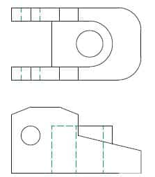
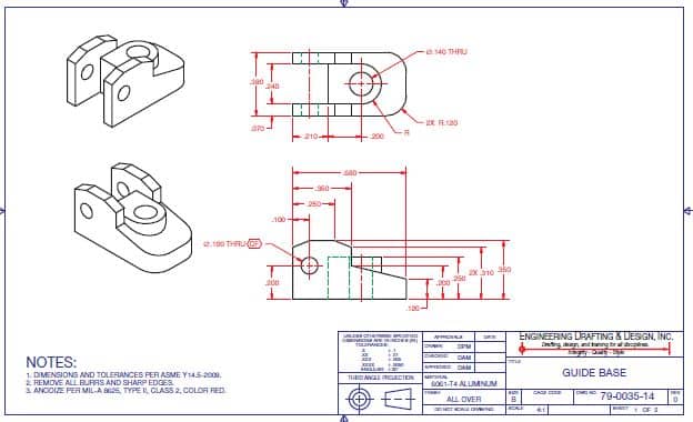
2D & 3D Drawings – The abbreviation for two-dimensional drawing is 2-D. It describes the view that comes with using height, width and length. Or it can be length and length dimensions. It comes with two-dimensional drawings that are established using design and drafting format. They commonly used for all engineering and architectural industries that relates to the disciplines with ease.
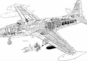
The two 2-D views represent the geometry of an aircraft part. It uses two views that come together and provide height, width, and length dimensions. The views mostly appear in the flat format and are rotated at 90 degrees from each other.
It comes with a complete 2-D drawing that include notes, dimensions, and text that describes view details and features. 2D drawings are the conventional and need to use method for communicating a project. Along with this, it uses an effective 2-D drawing accurately with describing design intent and product requirements. It covers the shape, size, and characteristics of all materials, features, finishes, and manufacturing methods.
A 2D drawing comes with typical documents that add project data for individuals and companies that are involved in the project. It covers relevant dates, design and approvals based on revision history. The 2D drawings offer computer numerical control (CNC) machine code. When compared with 3D surface and solid models, 2D drawings use few options to present and visualise the ideas. and limited ability to analyze and test product design. In addition, 2D drawings sometimes can be difficult to understand, if the reader is unfamiliar with interpreting 2D drawings.
THREE-DIMENSIONAL (3D) DRAWINGS
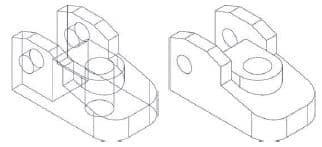
The abbreviation for three-dimensional is 3-D. It describes an object that have a height, a width, and depth dimensions. A wire-frame model offers the most basic 3-D CAD model, and contains data about object vertices and edges. The word vertices are plural when used for vertex. It points the edges that intersect. The wireframe is a term that describe the appearance of the model if they are constructed using wires.
Talking about three-dimensional surface, then it’s used as solid modelling placed in wireframe modelling in the CAD industry. The wireframe models come with a limited models use because they lack mass and surfaces. Without using the surfaces, the wireframe models are most difficult to visualise. It comes with creating an uncertain design intent. It does not require a true representation of a product, and lack volume.
Difference Between 2D 3D Drawings
Few tools come with an ability to change or hide the format of the lines fall through object features. It improves visualisation and create a 3-D representation way, along with a view for a 2-D drawing. However, the display can cause confusion. Especially when user view the complex objects. Without using the mass or the volume, the wireframe models come with a limited ability to analyse and test products.
Difference Between 2D 3D Drawings
A wireframe model comes with a small file size that offer fast display regeneration, store edge and vertex data. Whereas, the Wireframe models serve as a basis to construct 3-D surface and solid models. It provides the geometry for 2-D drawings. One can rotate and repurposing a wireframe model by producing the 2-D views. The Wireframe models uses 3D CNC machine code with ease.
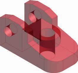
THREE-DIMENSIONAL (3D) SURFACE MODELS
A surface model use data about object vertices, edges, and surfaces. It comes with an outer boundary object that connects to vertices and edges. The surfaces display shade, color, reflection, and texture that helps to improve visualisation. Surfaces reduce uncertainty about design intent and offer a true representation of a product. Surface modelling provides the ability to create complex curves and forms.
3D surface modelling is commonly used for CAD industry, particularly used for conceptual design and industrial design to construct certain shapes. A surface model has zero thickness, lacks mass, and do not enclose a volume. The Surface models allow uses basic calculations that includes surface area and volume, but without mass. It comes with limited ability to analyse and test physical and inertial properties. With time the most common users of surface models are designers that primarily concerned with the external shape and appearance of a product.
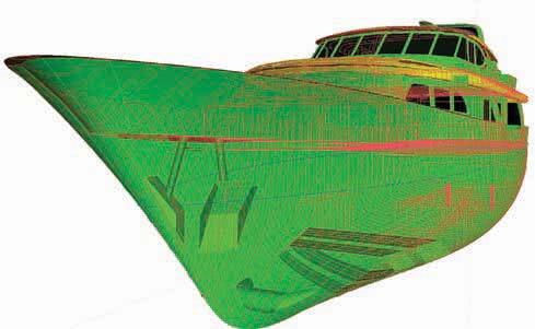
The hull design is a common application for surface modelling. The automobile body panel is another example of a product that needs to have an accurate surface. It covers animations, video games, virtual reality programs, and other programs that use similar requirements to form complex surfaces, especially when solids are unnecessary and file size is generally smaller than solid model files.
Surface models serve as a basis to construct 3-D solid models, and provide the geometry for 2-D drawings. It can rotate and repurpose a surface model to produce the 2-D views and display realistic surfaces on the 3-D representation.
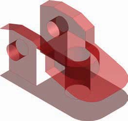
THREE-DIMENSIONAL (3D) SOLID MODELS
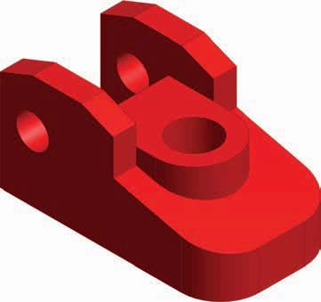
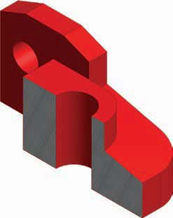
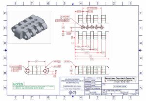
3A solid model is one of the most complex CAD formats that contains data about object edges, vertices, surfaces, and mass. Talking about Solid models, it’s most common 3-D CAD format used in the current CAD industry. It encloses a volume and has mass that allows designers and engineers to analyze the exterior and interior object characteristics. In contrast to a 2-D drawing, it offers a note that specifies the material assigned to a product.
2D and 3D Drawings
It comes with using 3-D surface model that displays a representation of material on surfaces. It assigns material to a solid model for analysing and testing physical and inertial properties. As a result, a solid model acts as a digital prototype of a product. It provides the geometry for 2-D drawings. We are best Australian Design & Drafting Services company to offer excellent CAD Design and Drafting. Contact Us to clear your doubts.
What is 2D drawing and 3D drawing?
2D drawing and 3D drawing are two different methods used to represent objects or scenes in visual art, design, and engineering. 2D Drawing: In 2D drawing, objects are represented using only two dimensions: length and width. These drawings are typically created on a flat surface, such as a piece of paper or a computer screen. Examples of 2D drawing include sketches, blueprints, floor plans, and technical drawings. 2D drawings are often used in fields such as graphic design, architecture, engineering, and illustration. They provide a simple and clear representation of objects but lack the depth and perspective that 3D drawings offer.
3D Drawing: In 3D drawing, objects are represented using three dimensions: length, width, and height. These drawings create the illusion of depth and perspective, making objects appear more realistic. 3D drawings are created using specialized software or by sculpting physical models. Examples of 3D drawing include computer-generated imagery (CGI), architectural renderings, product designs, and character animations. 3D drawings are widely used in industries such as animation, video games, film production, industrial design, and virtual reality. They allow for more detailed and immersive representations of objects, making them ideal for visualization and simulation purposes.
What is 2D vs 3D diagram?
A 2D diagram represents objects or concepts in two dimensions, typically on a flat surface such as a piece of paper or a computer screen. It uses length and width to depict objects, but lacks depth. Examples of 2D diagrams include floor plans, maps, blueprints, and graphs.
On the other hand, a 3D diagram represents objects or concepts in three dimensions, incorporating length, width, and height. It provides a more realistic depiction of objects by adding depth, making them appear more lifelike and tangible. Examples of 3D diagrams include architectural renderings, computer-generated models, and medical imaging scans like MRI or CT scans.
In summary, while both 2D and 3D diagrams serve to visually represent information, 2D diagrams are limited to two dimensions, while 3D diagrams add depth to create a more immersive and realistic representation.
There are several different CADD formats. The most recognized CADD formats include 2D drawings and 3D wireframe, surface, and solid models. In general, 2-D drawings and 3-D solid models are the most common CADD formats currently used in the industry. Three-dimensional surface models are also widely used, but often for specific applications. Three-dimensional wireframe models are rare in the current industry. Software specifies the CADD format, which usually focuses on a certain process such as 2-D drawing or 3-D solid modeling.
However, some systems offer tools for working in a variety of formats or the ability to use drawing or model content created in a different format. For example, you can often develop a 2D drawing from 3D model geometry or build a 3-D solid model from 3-D surface model geometry. A software add-on or separate application is sometimes required to work with multiple CADD formats.
Beyond the Basics: A Granular Look at CADD Formats
While the article rightly mentions 2D drawings and 3D models (wireframe, surface, solid) as the primary CADD formats, let’s delve deeper into their characteristics:
2D Drawings: The workhorse of many industries, 2D drawings offer a familiar and efficient way to represent designs. They excel in:
Manufacturing & Construction: Standard format for conveying precise dimensions and details.
Simple Designs: Ideal for quick projects that don’t require significant revisions.
Annotation & Communication: Effective for adding notes, dimensions, and other project-critical information.
3D Wireframe Models: These skeletal representations depict designs using lines and curves to connect points in 3D space. While less common today, they can be useful for:
Conceptualization & Early Design Stages: Providing a basic framework for visualizing initial design ideas.
Rapid Prototyping: Laying the groundwork for creating physical models.
3D Surface Models: A step up from wireframes, these models capture a design’s outer “skin” using mathematically defined surfaces. They find application in:
Organic Shapes & Complex Geometry: Representing curved and freeform elements effectively.
Visualization & Aesthetics: Creating realistic renderings for presentations or marketing purposes.
3D Solid Models: The crown jewel of CADD formats, solid models represent a design as a complete, volumetric entity. This allows for:
Advanced Analysis & Simulation: Performing stress analysis, calculating weight and volume, and simulating real-world behavior.
Detailed Design & Manufacturing: Creating highly accurate models for downstream processes like CNC machining or 3D printing.
Collaboration & Assembly: Facilitating seamless integration of different design components.
Understanding these distinctions empowers you to choose the right format for the job.
CHOOSING A CADD FORMAT
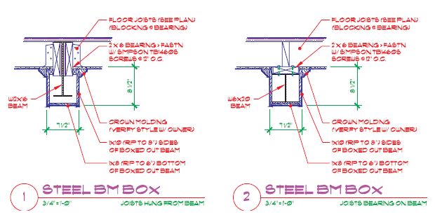
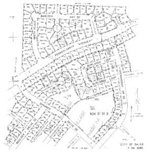
Several factors influence CADD software and format selection. Design and drafting practices and specific project requirements are primary considerations. Two-dimensional drawings are often required because they are the standard format in manufacturing and construction.
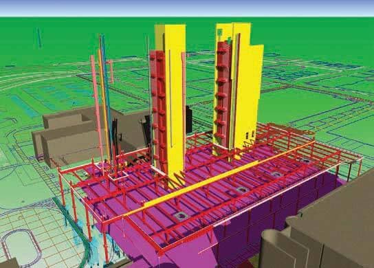
The figure shows a 2-D structural detail required for building construction. In addition, 2-D drawing is effective for a project that is quick to design, does not require extensive revision, and does not require advanced visualization, simulation, and analysis. Three-dimensional solid modelling is a better solution when a complex project requires extensive revision and when advanced visualization, simulation, and analysis are required. A 3-D representation of a design can help overcome visualization problems and produce a realistic, testable product model.
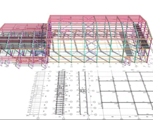
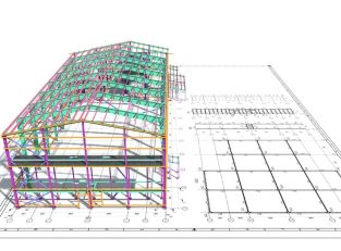
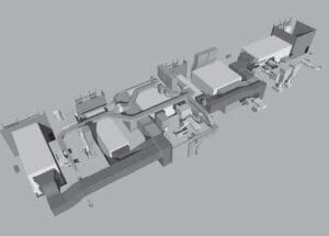
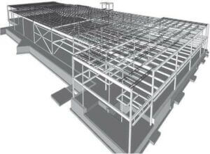
The figure shows a multidiscipline 3D model of a building providing structural, electrical, HVAC, and piping layouts. A combination of CADD formats and software may prove most effective for a project when applied correctly. Bringing the advantages of each CADD format together maximizes product design flexibility and effectiveness.
Collaboration and communication during a project also influence CADD software and format selection. Everyone involved in a project must be able to use a common CADD format or be able to convert data to a usable format easily. Costs are another important factor to consider when choosing a CADD software and format. For example, advanced 3-D solid modelling software is generally more expensive than 2-D drafting software. Operating a new or different CADD system also requires training and time to learn. Training is an expense and takes time from projects that produce income. A more capable CAD format, such as 3D solid modeling, is extremely cost-effective for some users, especially over time, but others will never benefit from the initial costs of the software and training. Several additional factors also influence selecting CADD software and format, including choosing a product and a format that is a known industry standard for project requirements, software stability and usability, the availability and effectiveness of support and training, and personal preference.
Beyond the List: Advanced CADD Format Considerations
The realm of CADD formats extends beyond the basic types mentioned earlier. Here’s a glimpse into some specialized options:
Neutral Formats (DXF, STEP): These formats allow data exchange between different CAD software programs, promoting interoperability.
Point Cloud Data: Captured from 3D scanners, point clouds represent objects as a collection of data points, providing a highly detailed representation of physical objects that can be integrated into CAD models.
Additive Manufacturing Formats (STL, AMF): Used for 3D printing, these formats translate CAD models into a format compatible with 3D printers for physical fabrication.
Understanding these advanced formats expands your design toolbox, allowing you to leverage the power of CADD for a wider range of applications.
Conclusion
CADD formats are more than just file extensions; they are the building blocks of your design workflow. By understanding their nuances and selecting the right format for your project needs, you can optimize your design process, enhance collaboration, and ultimately achieve superior design outcomes.
Australian Design & Drafting Services provides excellent service for CAD Design and Drafting. Contact Us for more info.
Computer-aided design and drafting (CADD) is the process of using a computer with CADD software for design and drafting applications. Software is the program or instructions that enable a computer to perform specific functions to accomplish a task. CADD refers to the entire range of design and drafting with the aid of a computer, from drawing basic 2-D objects to preparing complex 3-D models and animations. CAD is the acronym for computer-aided design and a common reference to computer-aided drafting. Computer-aided design and computer-aided drafting refer to specific aspects of the CADD process.
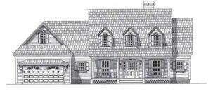
CADD offers solutions to most engineering drawing and design problems, and it allows for increasingly complex projects. Several industries and most disciplines related to engineering and architecture use CADD. Most engineering firms and educational institutions that previously used manual drafting practices have evolved to CADD. Professionals have come to rely on the power and convenience of CADD in all aspects of design and drafting. CADD systems include tools to accomplish any drawing and design requirement, such as preparing the 3-D model of a home shown in Figure.
THE CADD WORKSTATION
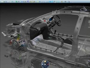
The CADD workstation consists of a variety of computer hardware. Hardware includes the physical components of a computer system, such as the computer, monitor, keyboard, mouse, and printer. The figure shows a modern CADD work-station. A CADD workstation relies on a computer for data processing, calculations, and communication with peripheral equipment. A peripheral is an external computer hardware device that uses the computer to perform functions that the computer cannot handle.
Peripherals provide input, output, and storage functions and services. Input means to put information into the computer that the computer acts on in some way. Input comes from devices such as the keyboard, a mouse or similar input device, or a digitizer. Output refers to information that the computer sends to a receiving device such as a monitor, a plotter, or a printer. Storage refers to disks and drives that allow the operator to store programs, files, symbols, and data.
CADD SOFTWARE PRODUCTS
The modern CADD workstation is powerful, inexpensive, and supports sophisticated CADD software. Many CADD software manufacturers exist, and numerous products are available to meet industry needs. Some CADD software is general purpose and can apply to any discipline. For example, Autodesk, Inc. produces AutoCAD for 2-D and 3-D design and drafting.
Other products focus on a specific CADD technology, industry, or discipline, such as drawings or models of mechanical parts and assemblies or those for architectural, civil, or structural engineering projects.
For example, Dassault Systèmes SolidWorks Corp. offers SolidWorks for 3-D solid modeling and 2-D drafting that is common in the manufacturing industry. Software specifically designed for CADD in the manufacturing industry is sometimes referred to as mechanical computer-aided design (MCAD) software. Some CADD programs support expanded, third-party, or add-on utilities intended to increase system usefulness for specifi c applications.
The CADD software industry changes constantly. Software manufacturers frequently update existing products or combine, change program names, or eliminate programs to adapt to the rapidly evolving CADD market. Software updates typically include additional and refined tools, increased software stability, and graphical user interface (GUI) enhancements.
Computer Aided Design and Drafting
The interface describes the items that allow you to input data to and receive outputs from a computer system. The GUI provides the on-screen features that allow you to interact with a software program. New products regularly emerge to respond to innovative technology and project requirements. Larger software manufacturers, such as Autodesk Inc., Dassault Systèmes, Parametric Technology Corporation, and Siemens PLM Solutions hold the greatest number of CADD users, and they traditionally have the ability to expand their products and acquire smaller software companies or existing software.
Some software manufacturers offer products intended to support various aspects of product development. For example, some software companies combine CADD and CAM tools for design, drafting, and manufacturing. A few software companies offer specific applications or software packages to help manage all aspects of a project, known as product life cycle management (PLM). PLM systems include tools for CADD, product data management (PDM) to organize and monitor project data, computer-aided engineering (CAE) for simulation and analysis, CAM, and presentation.
Alibre, Inc.
Alibre provides software generally for CADD in the manufacturing industry. Alibre Design is a 3-D solid modeling and 2-D drafting program. The Professional version of Alibre Design includes tools for sheet metal design and rendering. The Expert version of Alibre Design provides additional functions such as simulation and FEA, PDM, CAM, and extended translation tools. Translation occurs when converting data from the fi le system of one CADD system to another, and it is often necessary when sharing CADD data with others, such as consultants, manufacturers, and vendors. Most CADD soft-ware includes tools for some level of fi le translation. Separate translation software is available when necessary. Alibre also offers Alibre Personal Edition, which is a 3-D modeling and 2-D drawing software marketed to hobbyists.
Ashlar-Vellum
Ashlar-Vellum offers basic 2-D and 3-D CADD software. Graphite provides 2-D and 3-D wireframe drawing and modeling capabilities. Argon is a basic 3-D model-ing software for conceptual design, visualization, and translation. Xenon and Cobalt, which include additional functions, are 3-D modeling programs with 2-D drafting capabilities.
Autodesk, Inc.
Autodesk offers a wide variety of soft-ware. AutoCAD is general-purpose 2-D and 3-D CADD software and is the core Autodesk product. Autodesk provides variations of AutoCAD for unique markets, such as Auto-CAD LT for 2-D drafting, AutoCAD Electrical for electrical control system design, and AutoCAD Civil 3-D for civil engineering project design. Additional Autodesk products focus on specifi c CADD technology and industries, such as manufacturing, architecture, construction, infrastructure, media, and entertainment.
Autodesk® Inventor® is a 3-D solid modeling and 2-D drafting program generally for CADD in the manufacturing industry. Autodesk Inventor provides a comprehensive and flexible set of software for 3-D mechanical design, simulation, design visualization and communication, tooling creation, and 2-D documentation. Autodesk offers Autodesk Inventor Suites that combine Autodesk Inventor, AutoCAD Mechanical, and tools for specifi c applications, such as mold, tube and pipe, and cable and harness design. Some Autodesk Inventor Suites also include simulation and analysis functions. Autodesk Revit is a 3-D building design program with 2-D drafting and documentation capabilities. Versions of Autodesk Revit focus on design for architecture, mechanical, electrical, and plumbing (MEP), or building information modeling (BIM) for structural engineering. Autodesk manufactures numerous other software products, including Autodesk Algor Simulation for solid model simulation and FEA, Autodesk Vault for PDM, 3ds Max for 3-D modeling, animation, and rendering, and software to support the sustainable and environmentally friendly design and development.
Bentley Systems, Inc.
Bentley Systems focuses on software for engineering and construction infrastructure design, documentation, and operation. Infrastructure is the structures, facilities, and services required for an economy to function, such as buildings, roads and bridges, water supply and sewer systems, and power-supply and telecommunication systems. Micro Station is a general-purpose 2-D and 3-D CADD soft-ware and is the primary Bentley Systems product. Micro-Station also acts as a platform for other Bentley Systems software. For example, GEOPACK Civil Engineering Suite includes tools for civil engineering and transportation project design. Micro Station PowerDraft is a version of MicroStation mainly for 2-D drafting. Bentley Systems manufactures other software, including Project Wise for PDM, and ProConcrete for 3-D modeling, detailing, and scheduling of reinforced concrete structures.
Dassault Systèmes
Dassault Systèmes brands offer several soft-ware products generally focused on CAD and related technology for the manufacturing industry. CATIA is a project development system and is the main Dassault Systèmes brand product. CATIA provides tools for 3-D solid modeling and 2-D drafting and tools for specifi c applications, such as mold, tube and pipe, cable and harness, and electronic design. CATIA also offers simulation and analysis, CAM, and PDM functions. The additional Dassault Systèmes brand software focuses on specifi c aspects of PLM.
SolidWorks is a 3-D solid modeling and 2-D drafting program and is the core Dassault Systèmes SolidWorks (www. solidworks.com) brand product. Dassault Systèmes SolidWorks offers a standard version of SolidWorks and suites that incorporate SolidWorks with simulation, analysis, and PDM tools. SolidWorks Simulation includes tools for solid model simulation and FEA. SolidWorks Flow provides fluid-flow simulation and thermal analysis. Dassault Systèmes SolidWorks also manufactures software to support the sustainable and environmentally friendly design and manufacturing.
Google Inc.
Google SketchUp is a software intended to have an easy to use interface for creating, sharing, and presenting 3-D models. Common applications for Google SketchUp include sketching and modeling for visualization during the conceptual design phase of a project and creating presentation drawings that look hand-sketched or photorealistic. Google SketchUp also links to Google Earth for sketching relative to a physical location, such as modeling a building on an actual lot.
GRAPHISOFT
GRAPHISOFT focuses on software for the architecture, engineering, and construction (AEC) industry. ArchiCAD is a 3-D building design program with 2-D drafting and documentation capabilities; it is the main GRAPHISOFT product. MEP Modeler adds 3-D and 2-D MEP functions to ArchiCAD. Virtual Building is a 3-D digital database that tracks all elements that make up a building, allowing the designer to use items such as surface area and volume, thermal properties, room descriptions, costs, product information, and window, door, and finish schedules. Virtual refers to something that appears to have the properties of a real or actual object or experience. GRAPHISOFT also manufactures photo-realistic rendering software and software to support sustainable and environmentally friendly architectural design and construction.
IMSI/Design, LLC
IMSI/Design offers basic CADD software for general-purpose and project-specific applications. TurboCAD is the core IMSI/Design product. IMSI/Design provides variations of TurboCAD for unique markets, such as TurboCAD Designer for 2-D drafting, TurboCAD Deluxe for 2-D drafting and 3-D modeling, and TurboCAD Pro with additional 2-D and 3-D CADD functions. Additional IMSI/Design products focus on specifi c CADD technology and industries, such as Home & Landscape and Instant Architect for basic 2-D and 3-D home design.
Intergraph
Intergraph manufactures software for specific industries and projects, including the design, construction, and operation of plants, ships, offshore facilities, and transportation and utility systems. For example, SmartMarine 3-D is specialized software for 3-D model-ing, design, and documentation of marine structures, such as commercial ships. Intergraph also offers SmartSketch for 2-D drafting.
Iron CAD
IronCAD provides software generally for CADD in the manufacturing industry. IRONCAD is a 3-D solid modeling and 2-D drafting program with PDM functions. A third-party application offers simulation and FEA tools compatible with IRONCAD. INOVATE is a version of IRONCAD with fewer 3-D modeling functions and no 2-D drafting capabilities.
Kubotek Corporation
Kubotek manufactures CADD and CAM software. KeyCreator is a 3-D solid modeling and 2-D drafting program generally for CADD in the manufacturing industry; it is the chief Kubotek product. Kubotek Validation Tool confirms design accuracy during or after a specifi c activity, such as a design revision or data translation. Kubotek also manufactures KeyMachinest for CAM and maintains CADKEY for 3-D wireframe modeling.
Parametric Technology Corporation
Parametric Technology Corporation, or PTC, offers several software products generally focused on CADD in the manufacturing industry. Pro/ENGINEER is a 3-D solid modeling and 2-D drafting program and is the core PTC software. PTC provides various additions to the Pro/ENGINEER platform, including tools for CAE, CAM, and PDM: for example, Pro/ENGINEER Mechanica for simulation and FEA, Pro/ENGINEER Piping and Cabling Extension for pipe and cable design, and Pro/ENGINEER Reverse Engineering for automating reverse engineering. Reverse engineering is the process of converting an existing physical product into drawings or digital models, and it involves discovering the technological principles of a device, object, or system by analyzing its structure, function, and operation.
PTC manufactures other software, including Windchill for PDM, CoCreate for CAD, CAE, and PDM, and MathCAD for engineering calculations.
Siemens Corporation
Siemens Corporation offers a wide variety of products and services. The Siemens PLM Solutions (www.plm.automation. siemens.com) brand manufactures PLM software. NX ad-dresses each area of product development, and it is the primary Siemens PLM Solutions software. NX provides tools for 3-D solid modeling, 2-D drafting, and specific applications such as tool and fixture, routed system, and sheet metal product design. NX also offers simulation, FEA, CAM, and PDM functions. In addition to NX, Siemens PLM Solutions produces SolidEdge for 3-D solid modeling and 2-D drafting, generally for CADD in the manufacturing industry. The additional Siemens PLM Solutions brand software focuses on specifi c aspects of PLM.
Australian Design & Drafting Services provide excellent service for CAD Design and Drafting. Contact Us for more info
What is computer-aided design and drafting?
Computer-aided design and drafting (CADD), also known as computer-aided design (CAD), refers to the use of computer software to assist in the creation, modification, analysis, or optimization of designs for a wide range of applications.
CAD software allows designers, engineers, architects, and other professionals to create precise 2D drawings or 3D models of objects, buildings, mechanical parts, electrical circuits, and more. These digital representations can be manipulated, viewed from different angles, and tested for various factors such as stress, fluid dynamics, or thermal properties.
CAD software often includes tools for drafting, modeling, rendering, and simulation, enabling users to produce accurate and detailed designs efficiently. It has revolutionized the design process in many industries, leading to faster prototyping, reduced errors, and improved collaboration among team members.
What is computer aided drafting CAD used for?
Computer-aided drafting (CAD) is used in a variety of industries for designing and drafting technical drawings and plans with the assistance of computer software. Here are some common applications:
Architecture and Construction: CAD is extensively used by architects and engineers to create detailed plans for buildings, bridges, roads, and other structures. It allows for precise measurements, accurate representations of designs, and the ability to easily make changes. Mechanical Engineering: CAD software is indispensable in the field of mechanical engineering for designing machine parts, tools, and mechanical systems. It enables engineers to create 2D and 3D models, perform simulations, and analyze the performance of components. Product Design and Manufacturing: CAD is crucial in the product design process, allowing designers to create digital prototypes of products before they are manufactured. It facilitates the visualization of designs, helps in testing for functionality and ergonomics, and streamlines the manufacturing process. Electrical and Electronic Systems: CAD is used for designing circuit boards, electrical systems, and electronic components. It enables engineers to create schematics, layout PCBs (Printed Circuit Boards), and simulate electrical circuits to ensure optimal performance. Interior Design: CAD software is utilized by interior designers to create floor plans, furniture layouts, and interior designs for residential and commercial spaces. It helps in visualizing designs, experimenting with different layouts, and presenting ideas to clients. Urban Planning and GIS: CAD is employed in urban planning for creating detailed maps, land-use plans, and infrastructure designs. It plays a crucial role in visualizing proposed developments, analyzing spatial data, and making informed decisions about city planning. Aerospace and Automotive Industries: CAD software is used extensively in these industries for designing aircraft, spacecraft, automobiles, and other vehicles. It aids in creating complex assemblies, performing aerodynamic simulations, and optimizing designs for performance and safety.
Manual drafting, also known as hand drafting, describes traditional drafting practice using pencil or ink on a medium such as paper or polyester film, with the support of drafting instruments and equipment. This chapter also explains drawing scale, sheet size, and sheet format.
Computer-aided design and drafting (CADD) has replaced manual drafting in most of the drafting industry.
As a result, some of the information in this chapter primarily serves as a historical reference. However, both manual drafting and CADD require that you understand the basics of drafting. Concepts such as scale, sheet size, and sheet format are critical and universal to manual drafting and CADD. Also, some companies use CADD but have manual drafting equipment available that you should be able to recognize and operate at a basic level.
Professional manual drafting requires appropriate drafting of equipment and supplies. If you work in a modern CADD environment, manual drafting tools such as compasses, dividers, triangles, templates, and scales have less importance. However, they are still valuable for sketching, taking measurements, and other related activities. You can purchase drafting supplies and equipment in a kit or buy items individually. Manual drafting equipment is available from many local and online vendors. Search the Internet or a phone book for keywords or headings such as drafting equipment and supplies, blueprinting, architect supplies, and artist supplies. Always purchase quality instruments for the best results. The following is a list of items generally needed for typical manual drafting:
• Drafting furniture.
• One 0.3 mm automatic drafting pencil with 4H, 2H, and H leads.
• One 0.5 mm automatic drafting pencil with 4H, 2H, H, and F leads.
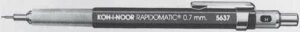
• One 0.7 mm automatic drafting pencil with 2H, H, and F leads.
• One 0.9 mm automatic drafting pencil with H, F, and HB leads.
• Sandpaper sharpening pad.
• Erasers recommended for drafting with pencil on paper.
• Erasing shield.
• Dusting brush.
• 6 in. Bow compass.
• Dividers.
• 8 in. 30-60 triangle.
• 8 in. 45 triangle.
• Circle template with small circles.
• Circle template with large circles.
• Irregular curve.
• Scales:
• Triangular architect’s scale.
• Triangular civil engineer’s scale.
• Triangular metric scale.
• Drafting tape.
• Lettering guide (optional).
• Arrowhead template (optional).
DRAFTING PENCILS AND LEADS
Automatic pencils are standard for manual drafting, sketching, and other office uses. The term automatic pencil refers to a pencil with a lead chamber that advances the lead from the chamber to the writing tip by the push of a button or tab when a new piece of lead needed. Automatic pencils hold leads of one width, so you do not need to sharpen the lead. The pencils are available in several different lead sizes.
Drafters typically have several automatic pencils. Each pencil has a different grade of lead hardness and is appropriate for a specific technique. This reduces the need to change leads constantly. Some drafters use a light blue lead for layout work. If your primary work is CADD, a combination of 0.5-, 0.7-, and 0.9 mm pencils and leads is good for sketching and related activities.
Lead Grades
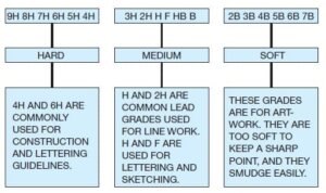
Lead grades of 2H and H are good in your automatic pencil for typical daily office use. The leads you select for line work and lettering depend on the amount of pressure you apply and other technique factors. Experiment until you identify the leads that give the best line quality. Leads commonly used for thick lines range from 2H to F, whereas leads for thin lines range from 4H to H, depending on individual preference.
Construction lines for layout and guidelines are very lightly drawn with a 6H or 4H lead. The Figure shows the different lead grades.
Compasses
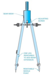
A compass is an instrument used to draw circles and arcs. A compass is especially useful for large circles, but using one can be time-consuming. Use a template, whenever possible, to make circles or arcs more quickly.
There are several basic types of compasses. A bow compass, shown in Figure, is used for most drawing applications. A beam compass consists of a bar with an adjustable needle, and a pencil or pen attachment for swinging large arcs or circles. Also available is a beam that is adaptable to the bow compass. This adapter works only on a bow compass that has a removable leg.
DIVIDERS
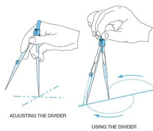
Dividers are used to transfer dimensions or to divide a distance into several equal parts. Dividers are also used in navigation to measure distance in nautical miles. Some drafters prefer to use bow dividers because the centre wheel provides the ability to make fine adjustments easily. Besides, the setting remains more stable than with standard friction dividers.
A functional divider should not be too loose or tight. It should be easy to adjust with one hand. You should always control a divider with one hand as you layout equal increments or transfer dimensions from one feature to another. Do not try to use a divider as a compass. The Figure shows how to handle the divider when used.
Proportional Dividers
Proportional dividers are used to reduce or enlarge an object without having to make mathematical calculations or scale manipulations. The centre point of the divider is set at the correct point for the proportion you want. Then you measure the original size line with one side of the proportional divider; the other side automatically determines the new reduced or enlarged size.
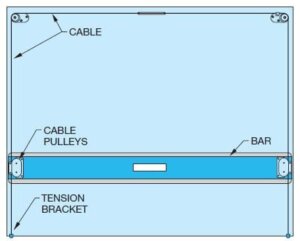
PARALLEL BAR
The parallel bar slides up and down a drafting board to allow you to draw horizontal lines. Use triangles with the parallel bar to draw vertical lines and angles. The parallel bar was common for architectural drafting because architectural drawings are frequently very large. Architects
using manual drafting often need to draw straight lines the full length of their boards, and the parallel bar is ideal for such lines.
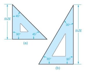
TRIANGLES
There are two standard triangles. The 30º-60º triangle has angles of 30-60-90. The 45 triangle has angles of 45-45-90. Some drafters prefer to use triangles in place of a vertical drafting machine scale, as shown in Figure. Use the machine protractor or the triangle to make angled lines. Using parallel bars, drafters utilize triangles to make vertical and angled lines.
Triangles can also be used as straightedges to connect points for drawing lines without the aid of a parallel bar or machine scale. Use triangles individually or in combination to draw angled lines in 15 increments Also available are adjustable triangles with built-in protractors that are used to make angles of any degree up to a 45 angle.
TEMPLATES
Manual drafting templates are plastic sheets with accurate shapes cut out for use as stencils to draw specific shapes. The most common manual drafting templates are circle templates for drawing circles and arcs. Templates for drawing other shapes, such as ellipses, and for letters are also common. Templates are also available for specific requirements and drafting disciplines. For example, use architectural templates to draw the floor plan and other symbols to scale. Electronic drafting templates have schematic symbols for electronic schematic drawings.
Circle Templates
Circle templates are available with circles in a range of sizes beginning with 1/16 in. (1.5 mm). The circles on the template are marked with their diameters and are available in fractions, decimals, or millimetres. Figure 2.10 shows the parts of a circle. A popular template is one that has circles, hexagons, squares, and triangles.
Always use a circle template rather than a compass. Circle templates save time and are very accurate. For best results, when making circles, keep your pencil or pen perpendicular to the paper. To obtain proper width lines with a pencil, use a 0.9 mm automatic pencil.
Ellipse Templates
An ellipse is a circle seen at an angle. Isometric circles are ellipses aligned with the horizontal right or left planes of an isometric box. Isometric ellipse templates automatically position the ellipse at the proper angle of 35 16′.
IRREGULAR CURVES
Irregular curves, commonly called French curves, are curves that have no constant radii. A radius curve is composed of a radius and a tangent. The radius on these curves is constant and ranges from 3 ft to 200 ft. (900-60,000 mm). Irregular curves are commonly used in highway drafting. Ship’s curves are also available for layout and development of ships hulls. The curves in a set of ship’s curves become progressively larger and, like French curves, have no constant radii. Flexible curves are also available that allow you to adjust to the desired curve.
DRAFTING MACHINES
A manual drafting machine is a machine that mounts to the table or board and has scales attached to an adjustable head that rotates for drawing angles. When locked in a zero position, the scales allow drawing horizontal and vertical lines and perpendicular lines at any angle orientation. The drafting machine vernier head allows you to measure angles accurately to 5′ (minutes). Drafting machines, for the most part, take the place of triangles and parallel bars. The drafting machine maintains a horizontal and vertical relationship between scales, which also serve as straightedges. A protractor allows the scales to be set quickly at any angle.
There are two types of drafting machines: arm and track. The track machine generally replaced the arm machine in the history of manual drafting. A major advantage of the track machine is that it allows the drafter to work with a board in the vertical position. A vertical drafting surface position is generally more comfortable to use than a horizontal table. When ordering a drafting machine, the specifications should relate to the size of the drafting board on which it is mounted. For example, a 37½ 3 60 in. (950-1500 mm) machine properly fits a table of the same size.
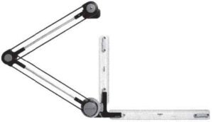
Arm Drafting Machine
The arm drafting machine is compact and less expensive than a track machine. The arm machine clamps to a table and through an elbowlike arrangement of supports allows you to position the protractor head and scales anywhere on the board. The Figure shows an arm drafting machine.
Track Drafting Machine
A track drafting machine has a traversing arm that moves left and right across the table and a head unit that moves up and down the traversing arm. There is a locking device for both the head and the traversing arm. The shape and placement of the controls of a track machine vary with the manufacturer, although most brands have the same operating features and procedures.
SCALES
A scale is an instrument with a system of ordered marks at fixed intervals used as a reference standard in measurement. A scale establishes a proportion used in determining the dimensional relationship of an actual object to the representation of the same object on a drawing. Use specific scales for mechanical, architectural, civil, and metric drawings.
Manual drafters use scales as measurement instruments to help create scaled drawings. In a CADD work environment, a scale is useful for sketching and taking measurements, as well as for related tasks. The scale is a universal and critical design and drafting concept.
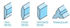
Scale Shapes
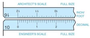
There are four basic scale shapes, as shown in Figure. The two-bevel scale is also available with chuck plates for use with standard arm or track drafting machines. Drafting machine scales have typical calibrations, and some have no scale reading for use as a straightedge. Drafting machine scales are purchased by designating the length needed-12, 18, or 24 in.-and the scale calibration such as metric, engineer’s full scale in tenths and half-scale in twentieths, or architect’s scale 1/4″ 5 1′ -0″. Many other scales are available. The triangular scale is commonly used in drafting and has different scale calibrations on each corner of the triangle. Common triangular scales are the architectural scale calibrated in feet and inches, mechanical scale calibrated in decimal inches, civil scale calibrated in feet and tenths of a foot, and the metric-scale calibrated in millimetres and centimetres.
Drawing Scale
Drawings are scaled so that the objects represented can be illustrated clearly on standard sizes of paper. It would be difficult, for example, to make a full-size drawing of a house. You must decrease the displayed size, or scale, of the house to fit properly on a sheet. Another example is a very small machine part that requires you to increase the drawing scale to show necessary detail. Machine parts are often drawn full size or even two, four, or ten times larger than full size, depending on the actual size of the part.
The selected scale depends on:
The actual size of the objects
The amount of detail to
The media size.
The amount of dimensioning and notes
In addition, you should always select a standard scale that is appropriate for the drawing and drafting discipline. The drawing title block usually indicates the scale at which most views are drawn or the predominant scale of a drawing. If the scale of a view differs from that given in the title block, the unique scale typically appears as a note below the corresponding view.
Mechanical Engineer’s Scale
The mechanical engineer’s scale is commonly used for mechanical drafting when drawings are in fractional or decimal inches. The mechanical engineer’s scale typically has full-scale divisions that are divided into 1/16, 10, and 50. The 1/16 divisions are the same as the 16 architect’s scale where there are 12 in. and each inch is divided into 1/16 in. increments (or sometimes 1/32 in. divisions). The 10 scale is the same as the 10 civil engineer’s scale, where each inch is divided into ten parts, with each division being .10 in. The 50 scale is for scaling dimensions that require additional accuracy because each inch has 50 divisions. This makes each increment 1/30 in. or .02 in. (1 4 50 5 .02). The Figure shows a comparison between the mechanical engineer’s scales. The mechanical engineer’s scale also has half-size 1:2 (1/2″ 5 1″), quarter-size 1:4 (1/4″ 5 1″), and eighth-size 1:8 (1/8″ 5 1″) options for reducing the drawing scale (see Figure 2.28). Figure 2.29 on page 53 shows a drawing that is represented at full scale (1:1), half-scale (1:2), and quarter-scale (1:4) for comparison.
DRAFTING MEDIA
The term media, as applied here, refers to the material on which you create drawings, such as paper or polyester film. The two main types of media used for manual drafting are vellum and polyester film, with vellum being the most commonly used. Several factors other than cost also influence the purchase and use of drafting media, including durability, smoothness, erasability, dimensional stability, and transparency.
Durability is a consideration if the original drawing will be extensively used. Originals can tear or wrinkle, and the images can become difficult to see if the drawings are used often. Smoothness relates to how the medium accepts line work and lettering. The material should be easy to draw on so that the image is dark and sharp without a great deal of effort on your part.
Erasability is important because errors need to be corrected, and changes are frequently made. When images are erased, ghosting-the residue that remains when lines are dif- ficult to remove-should be kept to a minimum. Unsightly ghost images reproduce in a print. Materials that have good erasability are easy to clean. Dimensional stability is the quality of the media to remain unchanged in size because of the effects of atmospheric conditions such as heat, cold, and humidity. Some materials are more dimensionally stable than others.
Reproduction
One thing most designers, engineers, architects, and drafters have in common is that their finished drawings are intended for reproduction. The goal of every professional is to produce drawings of the highest quality that give the best possible prints when reproduced. Many of the factors that influence the selection of media for drafting have been described; however, the most important factor in reproduction.
The primary combination that achieves the best reproduction is the blackest and most opaque lines or images on the most transparent base or material. Vellum and polyester film make good prints if the drawing is well done. If the only concern is the quality of the reproduction, ink on polyester film is the best choice. However, some products have better characteristics than others. Some individuals prefer certain products. It is up to individuals and companies to determine the combinations that work best for their needs and budgets.
SHEET SIZE AND FORMAT
STANDARDS
Most professional drawings follow specific standards for sheet size and format. The Australian Drafting Standard specifies the exact sheet size and format for engineering drawings created for the manufacturing industry. Other disciplines can follow Australian Drafting standards. However, architectural, civil, and structural drawings used in the construction industry generally have a different sheet format and may use unique sheet sizes, such as architectural sheet sizes. Follow sheet size and format standards to improve readability, handling, filing, and reproduction; this will also help ensure that all necessary information appears on the sheet.
When selecting a sheet size, consider the size of objects drawn; the drawing scale; the amount of additional content on the sheet, such as a border, title block, and notes; and drafting standards. In general, choose a sheet size that is large enough to show all elements of the drawing using an appropriate scale and without crowding. For example, the dimensioned views of a machine part that occupies a total area of 15 in. 3 6 in. (381 mm 3 153 mm), can typically fit on a 17 in. 3 11 in. (B size) or 420 mm 3 297 mm (A3 size) sheet.
DIAZO REPRODUCTION
Diazo prints are also known as ozalid dry prints and blue-line prints. The diazo reproduction process has been mostly replaced by photocopy reproduction and the use of CADD files for printing and plotting. Diazo printing uses a process that involves an ultraviolet light passing through a translucent original drawing to expose a chemically coated paper or print material under-neath. The light does not go through the dense, black lines on the original drawing, so the chemical coating on the paper beneath the lines remains. The print material is then exposed to ammonia vapour, which activates the remaining chemical coat-ing to produce blue, black, or brown lines on a white or colour-less background. The print that results is a diazo, or blue-line print, not a blueprint. The term blueprint is a generic term used to refer to diazo prints even though they are not true blueprints. Originally, the blueprint process created a print with white lines on a dark blue background.
PHOTOCOPY REPRODUCTION
Photocopy printers are also known as engineering copiers when used in an engineering or architectural environment. A photocopy printer is a machine for photographically reproducing material, especially by xerography. Xerography is a dry photographic or photocopying process in which a negative image formed by a resinous powder on an electrically charged plate is electrically transferred to and fixed as a positive image on a paper or other copying surface. Prints can be made on bond paper, vellum, polyester fi lm, coloured paper, or other translucent materials. The reproduction capabilities also include instant print sizes ranging from 45 percent to 141 percent of the original size.
Larger or smaller sizes are possible by enlarging or reducing in two or more steps. Almost any large original can be converted into a smaller-sized reproducible print, and then the secondary original can be used to generate additional photocopy prints for distribution, inclusion in manuals, or for more convenient handling. In addition, a random collection of mixed-scale drawings can be enlarged or reduced and converted to one standard scale and format. Reproduction clarity is so good that halftone illustrations (photographs) and solid or fine line work have excellent resolution and density.
The photocopying process and CADD printing and plotting have mostly replaced the diazo process. Photocopying has many advantages over diazo printing, including quality repro-duction in many sizes, use of most common materials, and no hazardous ammonia. A CADD system allows you to produce a quality hard copy print quickly. A hard copy is a physical drawing produced by a printer or plotter. The hard copy can be printed on vellum for further reproduction using the diazo or photocopy process.
PROPERLY FOLDING PRINTS
Prints come in a variety of sizes ranging from small, 8½ 3 11 in., to 34 3 44 in. or larger. It is easy to fi le the 8½ 3 11 in. size prints because standard file cabinets are designed to hold this size. There are file cabinets available called flat files that can be used to store full-size unfolded prints. However, many companies use standard file cabinets. Larger prints must be properly folded before they can be filed in a standard file cabinet. It is also important to fold a print properly if it is to be mailed.
Folding large prints is much like folding a road map. Folding is done in a pattern of bends that results in the title block and sheet identifi cation ending up on the front. This is desirable for easy identifi cation in the file cabinet. The proper method used to fold prints also aids in unfolding or refolding prints.
MICROFILM
Microfilm is photographic reproduction on film of a drawing or other document that is highly reduced for ease in storage and sending from one place to another. When needed, equipment is available for enlargement of the microfi lm to printed old vellum becomes yellowed and brittle. In addition, in case of a fire or other kind of destruction, originals can be lost and endless hours of drafting vanish. For these and other reasons, microfilm has been used for storage and reproduction of original drawings. Although microfilm storage of old drawings still exists in some companies, CADD files have replaced the use of microfilm for most modern applications.
CADD VERSUS MICROFILM
Microfilm was once an industry standard for storing and accessing drawings. Large international companies especially relied on the microfilm network to ensure that all worldwide subcontractors, vendors, clients, and others involved with a project were able to reproduce needed draw-ings and related documents. One advantage of microfilm was the ability to archive drawings-that is, store some-thing permanently for safekeeping.
The use of CADD in the engineering and construction industries has made it possible to create and store drawings electronically on a computer, optical disk, or other media. This makes it possible to retrieve stored drawings easily and quickly. A big advantage of CADD file storage involves using CADD drawings. When you retrieve CADD-generated drawings, they are of the same quality as when they were originally drawn. You can use CADD drawings to make multiple copies or to redesign a product efficiently. In addition to the maintained original quality of the stored CADD drawing, the drawing file can be sent anywhere in the world over the Internet or within a company’s intranet. The Internet is a worldwide network of communication between computers, and intranet links computers within a company or an organization.
CAD/CAM
The optimum efficiency of design and manufacturing methods is achieved without producing a single paper copy of a drawing of a part. Computer networks can directly link engineering and manufacturing departments by integrating computer-aided design (CAD) and computer-aided manufacturing or machining (CAM) software. This integration is referred to as CAD/CAM. The drafter or designer creates a 3-D model or 2-D engineering drawing of a part using CADD software. CAM software is then used to convert the geometry to computer numerical control (CNC) data that is read by the numerically controlled machine tools. Often, the CAD/CAM system is electronically connected to the machine tool. This electronic connection is called networking. This direct link is referred to as direct numerical control (DNC), and it requires no additional media such as paper, disks, CDs, or tape to transfer information from engineering to manufacturing.
Australian Design & Drafting Services provide excellent service for CAD Design and Drafting. Contact Us for more info
What are the equipments in drafting?
In traditional drafting, several essential tools and equipment are commonly used: Drawing Board: A flat, smooth surface on which paper is attached for drawing. Drafting Table: A specialized table with adjustable height and angle, designed for comfortable drafting work. Drafting Machine: Attaches to the drawing board or drafting table, enabling precise drawing angles and measurements. T-Square: A T-shaped ruler used to draw horizontal lines. One edge of the T-square rests against the edge of the drawing board for accuracy. Triangles: Triangular rulers used to draw vertical and diagonal lines. Common types include 30-60-90 and 45-45-90 triangles. Compasses: Used for drawing circles and arcs with precision. Drafting Pencils: Mechanical pencils with various lead thicknesses (e.g., 0.3mm, 0.5mm, 0.7mm) for drawing lines of different weights. Eraser Shield: A small metal or plastic template with various hole sizes to shield parts of the drawing while erasing. Erasing Tools: Erasers of different types, including kneaded erasers for gentle removal of graphite without smudging. Scale Ruler: A ruler with multiple scales for accurately measuring distances on the drawing. Templates: Pre-made shapes such as circles, squares, and ellipses for consistent drawing. Drawing Paper: High-quality paper suitable for drafting work, usually in standard sizes like A4 or A3. Drafting Brushes: Used to remove eraser shavings and other debris from the drawing surface. Drafting Tape: Low-tack adhesive tape used to secure the paper to the drawing board without damaging it. Light Table: A backlit surface that allows tracing of drawings and overlays for precise alignment.
What is the instrument used for measuring in manual drafting?
In manual drafting, one of the primary instruments used for measuring is the scale ruler. Scale rulers come in various types, including: Architect’s Scale: Designed for architectural drafting, an architect’s scale typically has multiple scales on each edge, allowing measurements in different units such as feet, inches, and fractions of an inch. Engineer’s Scale: Engineer’s scales are commonly used in engineering and technical drafting. They usually feature scales for measurements in decimal inches or millimeters. Metric Scale: These scale rulers are calibrated in metric units, such as millimeters or centimeters, and are used for drafting in countries that primarily use the metric system. Civil Engineering Scale: Similar to the architect’s scale but tailored for civil engineering applications, this scale ruler often includes specialized scales for measuring distances on maps, blueprints, or technical drawings.
There is a significant difference between an individual trained in the theories, principles, standards, and requirements of the career field and a true professional. Being a professional is more than holding a credential. A certificate or diploma is only an indication of knowledge in the area you have chosen to study. Many recently educated people search for a large salary, but they generally have only a moderate understanding of their career field and little or no training as a true professional.
The facts are simple. When employed, you typically sign an agreement indicating job requirements, work times, vacations, sick days, insurance provisions, and employer expectations.
Many employers have a dress code, a code of ethics, and other provisions you must follow. As an employee, you are an adult who is being paid to make things happen. You are a part of a working machine, but you are not the main wheel that makes it turn. Do your job, do it well, and keep the wheels turning, which is your primary function in an entry-level position.
In becoming a true professional, you need to keep in mind that with the availability of the Internet and other media, that your potential employer can check up on you and in many cases find out more than you want them to know. Facebook, MySpace, blogs, and other social networking areas on the Internet can be very damaging to your career if misused. As with your professional attitude, you need to keep some things private.
PROFESSIONAL NETWORK
You do need a professional network, and there are many of them such as LinkedIn or Plaxo that can help you network on a professional level. Now is the time to exhibit responsibilities to yourself and your employer.
In my current role, I am in constant contact with the leaders of the industry, representing some of the most prestigious manufacturing, engineering, architectural, and industrial firms in the world. When discussing the employment of future drafters and designers, I often request information on the reasons one individual is chosen over another when they are equally qualified. The answer is consistent; they employ those who reflect professionalism in all aspects of their individuality and areas of training.
PROFESSIONAL FACTS
The following are 15 facts that make you a professional:
You must understand that your education begins after you have achieved your Your credentials only expose you to the knowledge and skills needed to perform the job. Real learning comes from day-to-day experience over many years.
Consider the interview process, the interviewer, and the type of company when seeking to Investigate the company and determine what they do, their geographic area, and who owns the company. The company mission and employee expectations should match your goals and objectives.
If you are seeking a career, do not take a job just to be Dissatisfaction may show in your work and performance, and it may result in you seeking new employment or being terminated. Employment changes can make it difficult to becoming reemployed. You should always keep a position for two or more years.
Leave your attitude at You should show gratitude for your employment. Be proud that this company thinks you have the potential to be a part of its working family. Keep in mind that you are not the owner.
Keep your opinion to yourself, focus on your job, and shape your This will bring you more attention and give you more excellent opportunities. Share improvement ideas with your supervisor. Ask if your work is acceptable and if there is anything that you can do better. Accept criticism with modesty.
Many co-workers will do anything to advance, which is an unethical fact of survival in This activity can lead to discontent. Remember, you work for your supervisor, your job is to improve the product, produce a product, and increase company profits. Negative actions toward you by co-workers reflect their own inability to carry out their duties.
Acting professional is a big part of your new You hold credentials, and with them comes a code of ethics that professionals follow. Here are some guidelines: (1) Be at your workstation, the computer turned on, chair adjusted, and ready to work a few minutes before work time. (2) Take your breaks at the designated. This is when you typically go to the restroom, get a coffee refill, or eat a snack. Work time is for production. (3) Your scheduled lunchtime includes You may find it more convenient to eat at work and have time to relax or do personal things. (4) Quitting time can be exciting, but do not stop early just to be out the door at 5 P.M. sharp. Complete a project and then deliver it to your supervisor if it takes a few minutes. You will have a head start on tomorrow and your career.
Dress well for your interview and on the job, providing a professional Men should wear a shirt and tie, jacket, dress pants, and polished leather shoes with laces. Women should wear professional style clothing, fitting to the employment atmosphere. Women should avoid wearing dresses for the interview. Women should wear dress pants or a skirt, blouse, and matching jacket, or a pants suit, and avoid necklines more than four fingers below the high point of your sternum. Patent leather or athletic shoes should not be worn by either sex. Shoes should coordinate with your clothing and should be flats or low heels. Avoid noisy shoes. Wear professional colour such as navy, black, or grey. Do not wear a white, yellow, or chartreuse jacket. Your shirt or blouse should be white, light blue, or a pastel colour. Men should wear a tie that coordinates with the jacket and pants and wear a belt that matches shoe colour. In today’s liberal workforce, unisex clothing is readily available, and some of it looks sharp. However, in the interview process, make sure your clothing is cut to fit your body style. Accessories should be moderate, with no visible necklaces or dangling earrings. Cologne and perfume should be very subdued. For men and women, exposed body piercings in your nose, lips, and tongues and multiple sets of earrings should not be worn at the interview.
Personal choices should be used on personal time or when found to be acceptable. Otherwise, you could jeopardize your employment opportunity. Keep in mind, you are applying for a job, and you do not know the preference of the company or the interviewer. The company makes the rules. Do not try to change policy if you want to keep your place. Observe the company dress code, so you know how to dress when you are employed.As a new hire, you should dress conservatively even if you see others are wearing jeans and polo shirts. If every- one wears shirts and ties, you do the same and make sure you have a jacket. Having a jacket or sport coat is good in case you need to attend a meeting. If the job requires you to go to manufacturing or to the field, you should have an appropriate change of clothes or cover-up. Finally, regardless of the dress code, keep a change of clothes in your car and be ready for an emergency dress up or dress down in a few minutes.
Self-improvement is a good investment in the job. Research on work, processes, clients, and another project-related issue while on your own time. This can improve your production, broaden your mind, discover new project ideas, find software solutions and production methods, or network with other professionals.
Most employment communication is proprietary and should not be discussed with anyone other than your supervisor or involved co-workers. Do not take information from work to home, unless approved by your supervisor.
Write personal e-mails and make personal phone calls after work or on your personal cell phone outside the of- fice during break or at lunch. Using company equipment and company time is only for company business.
After employment, you need to start preparing for you next move up the career ladder. Your employer may offer educational benefits. If you have access to the Internet at home, you can do webinars and take online training and technical training or expand your formal education. Your new knowledge, ability to speak on the technical subjects, and performance at work indicate your improvement without bragging. Provide information about your expanded learning during your annual reviews.
Completion of your education is only one step in the overall progression of your career track. You should seek industry certification with a professional organization. Certification is based on industry standards and required knowledge at a specific level in the profession, and it is offered by industry organizations who are experts in the field. Certification competencies provide minimum performance and knowledge levels to your employer. Certifications can be related to software, codes, standards, technical writing, and other subjects. Additional training reinforces your abilities and your employability.
Keep a work journal as an organizational tool and to improve your growth as a professional. Include specific assignment information, assignment performance, individuals involved, specific times and places related to the assignment, when you go to lunch, change projects, talk to a co-worker about a previous project, or attend a meeting about a new project. Entries made by time and date will stand firm in a challenge. The more you document, the better.
While in school and after, you should be a member of any professional organization that relates to your profession. ADDA and Skills USA offer student memberships for the drafting profession. By being involved in professional associations, you will find a network of professionals who can assist you in every phase of your career path and offer opportunities, advice, and guidance you cannot receive anywhere else. As you leave your school and enter the workforce, you should retain your membership in the professional organization and become as active as possible.
Most organizations provide you with professionally rewarding volunteer opportunities on committees and groups to assist the profession. As you gain experience, you will see yourself working on projects with little assistance, moving up the corporate steps, being given more responsibility and increased compensation, and having opportunities you hoped for when you were first employed.
SUMMERY
The following summarizes our profession:
Drafting is the foundation and stepping-stone of any aspiring architect and engineer. It is a tedious profession, with days filled with non- stop drawing and making models of designs. It is through this process that one is able to learn to develop new skills and be introduced to styles that can be used as inspiration for personal design preferences in the future. Drafting molds the builders and designers of the future. Drafting is the profession of the hardworking and the persevering, the patient and the creative, the ambitious and the proud.
The term drafter commonly refers to a man or woman who is employed in the drafting profession. Other general-purpose titles include draftsperson, design drafter, drafting technician, engineering drafter, CADD operator, and CADD technician. A job title can also be discipline or task specific. For example, a cad drafter who works for a civil engineering firm is a civil drafter, civil engineering drafter, construction drafter, or civil CADD technician. Several industries and most engineering and architectural related fields require drafters.
According to the Australian Department of Labor, most drafters work in the following industries:
Professional, scientific, and technical services.
Manufacturing
Construction
Administrative and support services.
Drafters prepare technical drawings and plans used by production and construction workers to build everything from microchips to skyscrapers. Drafters’ drawings provide visual guidelines and show how to construct a product or structure. Drawings include technical details and specify dimensions, materials, and procedures. Drafters fill in technical details using drawings, rough sketches, specifications, and calculations made by engineers, surveyors, architects, or scientists. For example, many drafters use their knowledge of standardized building techniques to draw Notice edit the details of structures.
Most drafters use CADD systems to prepare drawings. Accordingly, some drafters may be referred to as CADD operators. With CADD systems, drafters can create and store drawings electronically so that they can be viewed, printed, or programmed directly into automated manufacturing systems. CADD systems also permit drafters to prepare variations of a design quickly. Although drafters use CADD extensively, they still need knowledge of traditional drafting techniques in order to fully understand and explain concepts. Some use their understanding of engineering and manufacturing theory and standards to draw the parts of a machine; they determine design elements, such as the numbers and kinds of fasteners needed to assemble the machine. Drafters use technical handbooks, tables, calculators, and computers to complete their work.
DRAFTING FIELDS
Drafting is a broad occupation. There are many drafting fields and several drafting or related occupations within each fi eld. The most common drafting fields include architecture, civil and electrical engineering, electronics, mechanical engineering, and industrial process-pipe drafting.
Drafting, in general, has one basic description, but specific drafting areas have unique conceptual and skill characteristics. Drafters perform general duties described under the title of drafter in all drafting disciplines. Most drafters rely on knowledge of engineering or architectural principles, mathematical formulas, physical laws, and manufacturing or construction processes and limitations.
Drafters typically work from analyzes, standards, specifi cations, sketches, engineering drawings, models, prototypes, verbal instructions, ideas, and related design data. Drafters then perform discipline and project specific tasks that require certain knowledge and skill. For example, an automotive design drafter requires knowledge of automotive vehicle design and manufacturing.
Drafters often create a variety of drawings even though they may be employed in a certain fi eld or focus on a specific product. For example, an architectural drafter may be involved in preparing structural, electrical, plumbing, and civil drawings.
A mechanical drafter may participate in simulation and analysis studies and create electronic drawings and technical illustrations. Drafters often work with a team, individuals of the same discipline, and others related to a specific project. For example, architectural drafters typically work with architects, architectural designers, and related architecture, engineering, and construction professionals.
Aeronautical Cad Drafter
Aeronautical drafting is a specialization of mechanical drafting. Aeronautical drafters may create CADD models and drawings of aeroplanes, missiles, spacecraft, and components and related equipment, such as launch mechanisms.
Architectural Cad Drafter
Architectural drafters prepare CADD models and drawings of the architectural and structural features of a building. The figure is an example of an architectural elevation. The figure shows examples of architectural details. Architectural drafters rely on knowledge of building materials, codes, construction methods, and engineering practices. Architectural drafters work from specifications, sketches, and rough drafts. Architectural drafters may specialize in a type of building, such as residential or commercial, or construction material, such as reinforced concrete, masonry, steel, or timber.
Automotive Design Cad Drafter
Automotive design drafting is a specialization of mechanical drafting. Automotive design drafters develop working layouts and master drawings of automotive vehicle components, assemblies, and systems.
Casting, Forging, and Mold Cad Drafter
Casting, forging, and mould drafting is a specialization of mechanical drafting. Casting, forging, and mould drafters create CADD models and drawings for castings, forgings, and modelled parts. Castings, forgings, and moulded parts require special knowledge and attention to die and mould design, shrinkage allowances, and various other factors such as corner radii.
Civil Cad Drafter
Civil drafters prepare CADD models and drawings used in construction or civil engineering projects, such as highways, bridges, pipelines, flood-control projects, and water and sewage systems. The figure shows an example of a civil subdivision plan. Civil drafters create topographical and relief maps, and plot maps and charts showing profiles and cross-sections, indicating the relation of topographical contours and elevations to buildings, retaining walls, tunnels, overhead power lines, and other structures.
Civil drafters prepare detailed drawings of structures and installations, such as roads, culverts, fresh-water supplies, sewage-disposal systems, dikes, wharves, and breakwaters.
Civil drafters also compute the volume of the tonnage of excavations and fills and prepare graphs and hauling diagrams used in earthmoving operations. Civil drafters may accompany survey crew in field to locate grading markers or to collect data required for revision of construction drawings. A topographical drafter is a civil drafter who specializes in drafting and modifying topographical maps from surveying notes and aerial photographs.
Cartographic Cad Drafter
A cartographic drafter, also known as a cartographer, draws maps of geographical areas to show natural and constructed features, political boundaries, and other features. Cartographers collect, analyze, and interpret geographic information provided by geodetic surveys, aerial photographs, and satellite data. Cartographers research, study and prepare maps and other spatial data in digital or graphic form for legal, social, political, educational, and design purposes. Cartographers may also work with and develop a geographic information system (GIS).
Commercial Cad Drafter
Commercial drafting is a specialization of architectural drafting. A commercial drafter, also known as a facilities drafter, is responsible for laying out the location of buildings, planning the arrangements of offices, large rooms, store buildings, and factories, and drawing charts, forms, and records. A commercial drafter may also create 3-D rendered models.
Directional Survey Cad Drafter
Direction survey drafting is a specialization of civil drafting. Directional survey drafters plot oil- or gas-well boreholes from photographic subsurface survey recordings and other data. Directional survey drafters compute and represent diameter, depth, degree, and direction of inclination, location of equipment, and other dimensions and characteristics of boreholes.
Electrical Cad Drafter
Electrical drafters generate CADD models and drawings of electrical equipment, wiring diagrams, circuit board assembly diagrams, and layout drawings used by construction crews and repairers who erect, install, and repair electrical equipment and wiring in communications centres, power plants, industrial establishments, commercial and domestic buildings, and electrical distribution systems. An electric-cable diagrammer is an electrical drafter who specializes in preparing detail cable layout and diagrams for cable installation.
Electronic Cad Drafter
Electronic drafters produce CADD models and drawings, such as wiring diagrams, layout drawings, mechanical detail drawings, and drawings of intermediate and final assemblies that are used in manufacturing, assembling, installing, and repairing electronic devices and components, printed circuit boards, and equipment. Electronic drafters examine electronic schematics and supporting documents received from design engineering departments to develop, compute, and verify specifications in drafting data, such as configuration of parts, dimensions, and tolerances.
Geological Cad Drafter
Geological drafters draw maps, diagrams, profiles, cross-sections, directional surveys, and subsurface formations to represent geological or geophysical stratigraphy and locations of gas and oil deposits. Geological drafters correlate and interpret data obtained from topographical surveys, well logs, and geophysical prospecting reports and use special symbols to denote geological and geophysical formations or oil field installations.
Geophysical Cad Drafter
Geophysical drafters draw subsurface contours in rock formations from data obtained by geophysical prospecting. Geophysical drafters plot maps and diagrams from computations based on recordings of seismographs, gravity meters, magnetometers, and other petroleum-prospecting instruments and from prospecting and surveying field notes. Geophysical drafters some- times receive a title such as a seismograph drafter, according to a specific method of prospecting.
Heating, Ventilating, and Air-Conditioning Cad Drafter
Heating, ventilating, and air-conditioning drafters generally work for an HVAC engineering firm developing contract documents from engineering schematics. HVAC drafting may involve light design work in sizing and routing systems to conform to the allotted space with the building structure, as well as calculating heat loss and heat gain for buildings for use in determining equipment specifications. HVAC drafting may also involve trade-to-trade coordination on an elemental level.
A refrigeration drafterspecializes in drawing plans for the installation of refrigeration equipment. A detail drafter, or detailer, works for an HVAC contractor developing 3-D models, detailed shop and installation drawings, performing trade-to-trade coordination to a finished degree and developing fabrication cut sheets. Detailers can also be involved in download to or input into a sheet metal fabrication software program.
Industrial Process-Pipe Cad Drafter
An industrial process-pipe drafter-also known as an industrial pipe drafter, a piping drafter, and a pipeline drafter– prepares CADD models and drawings used in the layout, construction, and operation of oil and gas fields, refineries, chemical plants, and process piping systems.
Industrial process-pipe drafters develop detail drawings for the construction of equipment and structures, such as drilling derricks, compressor stations, and gasoline plants; frame, steel, and masonry buildings; piping manifolds and pipeline systems; and for the manufacture, fabrication, and assembly of machines and machine parts.
Industrial process-pipe drafters prepare maps to represent geological stratigraphy, pipeline systems, and oil and gas locations, using field survey notes, geological and geophysical prospecting data, and aerial photographs.
An oil and gas drafter is an industrial process-pipe drafter who specializes in oil and gas industrial pipe drafting.
Landscape Cad Drafter
Landscape drafters prepare CADD models and drawings from rough sketches or other data provided by landscape architects. Landscape drafters may prepare separate detailed site plans, grading and drainage plans, lighting plans, paving plans, irrigation plans, planting plans, and drawings and details of garden structures. Landscape drafters may build models of proposed landscape construction and prepare coloured drawings for presentation to clients.
Mechanical Cad Drafter
The manufacturing industry uses mechanical drafting, its name derived from mechanisms. The construction industry also uses mechanical drafting, but the term refers to drafting HVAC systems, which is the mechanical portion of an architectural project.
In general, mechanical drafting is the core of the engineering drafting industry. The terms engineering drawing and engineering drafting used throughout all drafting disciplines.
A mechanical drafter, also known as an engineering drafter, is a drafter associated with mechanical drafting for the manufacturing industry.
Mechanical drafters create CADD models and drawings of machinery and mechanical devices, indicating dimensions and tolerances, fastening and joining methods, and other engineering data and requirements. Mechanical drafters draw multiple-view part, assembly, subassembly, and layout drawings as required for manufacture and repair of machines and equipment. The figure shows an example of a part drawing.
Marine Cad Drafter
Marine drafting is a specialization of mechanical and structural drafting. Marine drafters develop CADD models and drawings of structural and mechanical features of ships, docks, and other marine structures and equipment.
Patent Cad Drafter
Patent drafters prepare clear and accurate drawings of varied sorts of mechanical devices for use of a patent lawyer in obtaining patent rights. The “Patents” section toward the end of this chapter provides additional information on patents and patent drawings.
Photogrammetrist
Photogrammetrists analyze source data and prepare mosaic prints, contour-map profi le sheets, and related cartographic materials that require technical mastery of photogrammetric techniques and principles.
Photogrammetrists prepare original maps, charts, and drawings from aerial photographs and survey data and apply standard mathematical formulas and photogrammetric techniques to identify, scale, and orient geodetic points, estimations, and other planimetric or topographic features and cartographic detail.
Photogrammetrists graphically represent aerial photographic detail, such as contour points, hydrography, topography, and cultural features, using precision stereo plotting apparatus or drafting instruments.
Photogrammetrists revise existing maps and charts and correct maps in various states of compilation. Photogrammetrists also prepare rubber, plastic, or plaster 3-D relief models.
Plumbing Cad Drafter
A plumbing drafter, also known as a pipe drafter, specializes in CADD models and drawings for installing plumbing and piping equipment in residential, commercial, and industrial settings. Commercial and industrial piping relate closely to industrial process-pipe drafting.
Structural Cad Drafter
Structural drafters create CADD models and drawings for structures that use reinforcing steel, concrete, masonry, wood, and other structural materials. Structural drafters produce plans and details of foundations, building frame, floor and roof framing, and other structural elements.
A detail drafter, or detailer, works for a structural contractor developing 3-D models, detailed shop drawings, and installation drawings, performing trade-to-trade coordination to a finished degree, and developing fabrication drawings. Detailers may also be involved in downloading to or inputting into a structural component fabrication software.
Technical Illustrator
Technical illustrators layout and draw illustrations for reproduction in reference works, brochures, and technical manuals dealing with assembly, installation, operation, maintenance, and repair of machines, tools, and equipment.
Technical illustrators prepare drawings from blueprints, design mockups, and photographs by methods and techniques suited to specified reproduction process or final use, photo-offset, and projection transparencies, using drafting and optical equipment.
Technical illustrators create schematic, perspective, axonometric, orthographic, and oblique-angle views to depict functions, relationships, and assembly sequences of parts and assemblies such as gears, engines, and instruments.
Technical illustrators also create rendered drawings and 3-D models, and they may draw cartoons and caricatures to illustrate operation, maintenance, and safety manuals and posters.
Tool-and-Die Design Cad Drafter
Tool-and-die design drafting is a specialization of mechanical drafting. Tool-and-die design drafters prepare CADD models and detailed drawing plans for manufacturing tools, usually following designs and specifications indicated by tool designers.
EDUCATION AND QUALIFICATIONS
The design and drafting profession can provide a rewarding career for people who enjoy detailed work and have a mechanical aptitude and ability to visualize. Math and communication skills are also important. The following information describes education and qualification requirements for an entry-level drafting position.
High school courses in mathematics, science, computer technology, design, computer graphics, and drafting are useful for people considering a drafting career. However, employers in the drafting industry prefer applicants who have at least two years of postsecondary training in a drafting program that provides strong technical skills and considerable experience with CADD systems.
Employers are most interested in applicants with a strong background in fundamental drafting principles;well-developed drafting skills; knowledge of drafting standards, mathematics, science, and engineering technology; a solid background in CADD techniques; and the ability to apply their knowledge to a broader range of responsibilities. Future students should contact prospective employers to ask which schools they prefer and contact schools to ask for information about the kinds of jobs their graduates have, the type and condition of instructional facilities and equipment available, and teacher qualifications.
Many technical institutes, community colleges, and some four-year colleges and universities offer drafting programs. Technical institutes offer intensive technical training, but they provide a less general education than do community colleges Technical institutes may award either certificates or diplomas and programs can vary considerably in length and in the types of courses offered.
Many technical institutes offer two-year associate degree programs. Community colleges offer programs similar to those in technical institutes but include more classes in drafting theory and also often require general education classes. After completing a two-year associate degree program, graduates may obtain jobs as drafters or continue their education in a related field at a four-year college. Most four-year colleges do not offer training in drafting, but they do offer classes in engineering, architecture, and mathematics that are useful for obtaining a job as a drafter. Technical training obtained in the armed forces can also apply in civilian drafting jobs. Some additional training may be necessary, depending on the technical area or military specialty.
Mechanical drafting-the type of drafting done for the manufacturing industry-offers the fundamental standards involved in the design and drafting profession. However, there are a variety of design and drafting discipline categories. Training differs somewhat within the drafting specialties, although the basics, such as mathematics, are similar. In an electronics drafting program, for example, students learn how to show electronic components and circuits in drawings. In architectural drafting, students learn the technical specifi cations of buildings.
Some educational programs provide training in specifi c disciplines, whereas others provide diversifi ed training in several areas. The opportunity to experience more than one discipline allows you to find an industry that you prefer.
General Qualifications and Certification
Mechanical ability and visual aptitude are important for drafters. Prospective drafters should be able to perform detailed work accurately. Artistic ability is helpful in some specialized fields, as is knowledge of manufacturing and construction methods. In addition, future drafters should have good interpersonal skills because they work closely with engineers, surveyors, architects, and other professionals and sometimes with customers.
Advancement
Opportunities for advancement for drafters are excellent, although dependent on the advancement possibilities of a specific employer. Advancement also depends on your skill, initiative, ability, product knowledge, attitude, ability to communicate, continued education, and enthusiasm.
Entry-level or junior drafters usually do routine work under close supervision. After gaining experience, drafters may become intermediate drafters and progress to more difficult work with less supervision. At the intermediate level, drafters may need to exercise more judgment and perform calculations when preparing and modifying drawings. Drafters may eventually advance to senior drafter, designer, or supervisor.
An entry-level drafting position may not be in your chosen field, but you should be able to find employment in your desired area with experience and an open job market. Opportunities are available that allow people to expand career potential into related areas such as tool design and cartography. Many people who enter the drafting industry begin to move up quickly into the design, checking, purchasing, estimating, and management.
Many employers pay for continuing education. Additional education for advancement usually includes increased levels of mathematics, pre-engineering, engineering, software, and advanced drafting. Appropriate college degrees may allow drafters to go on to become engineering technicians, engineers, or architects. Drafting has traditionally been an excellent way of designing, engineering, and management.
DRAFTING JOB OPPORTUNITIES
Drafting job opportunities, which include all possible drafting employers, fluctuate with national and local economies. Employment as a drafter remains tied to industries that are sensitive to cyclical changes in the economy, primarily construction and manufacturing.
A slowdown or speedup in construction and manufacturing nationally affects the number of drafting jobs available. The economic effect on drafting job opportunities also occurs at the local level or with specific industries. For example, construction may be strong in one part of the country and slow in another, so the demand for drafters in those localities is strong or slow accordingly.
Fewer drafters are required when large manufacturers, such as automobiles, experience poor sales. More drafters are required when industries such as high-tech expand. In addition, a growing number of drafters should continue to find employment on a temporary or contract basis as more companies turn to the employment services industry to meet their changing needs.
Local demands also generally control the types of drafting jobs available. Each local area usually has a need for more of one type of drafting skill than another. In general, metropolitan areas where manufacturing is strong offer more mechanical drafting jobs than rural areas, which typically offer more civil or structural drafting jobs than other disciplines. Drafting curriculums in different geographical areas usually specialize in the fields of drafting that help fill local employment needs.
A broader range of opportunities exists in many local areas because of the flexibility of electronic data transfer, making it possible to complete tasks worldwide. Some drafting programs offer a broad-based education so graduates can have versatile employment opportunities. When selecting a school, research curriculum, placement potential, and local demand. Talk to representatives of local industries for an evaluation of the drafting curriculum.
SEARCHING FOR A DRAFTING POSITION
Entry-level drafting positions require you to be prepared to meet the needs and demands of the industry. Entry into the drafting career marketplace depends on your training and ability and on the market demand. Your training, skills, and personal presentation are especially important in a poor economic environment, and these can make the difference in finding an employment opportunity.
A two-year, postsecondary degree in drafting can also provide a big advantage when seeking a position in the drafting industry. Programs of this type normally have a quality cross-section of training in design and drafting, math, and communication skills. Two-year, postsecondary drafting programs often have a job- preparation and placement services to aid their graduates.
Many of these schools have direct industry contacts that help promote hiring opportunities. Training programs also often have cooperative work experience (CWE) or internships in which their students work in the industry for a designated period while completing degree requirements.
These positions allow a company to determine if the student is a possible candidate for full-time employment and provide the student with valuable on-the-job experience to include on a résumé. Even if you do not go to work for the company where you do CWE or an internship, you can get a letter of recommendation for your portfolio.
When the local economy is doing well and drafting job opportunities are plentiful, it may be possible to find a job with less than a two-year college degree. If you want to find entry-level employment in a job market of this type, you can take intensive training in CADD practices. The actual amount of training required depends on how well you do and whether you can match an employer who is willing to hire with your level of training. Many people have entered the industry in this manner, although you would be well advised to continue schooling toward a degree while you are working.
Job-Seeking Strategy
The following are some points to consider when you are ready to seek employment:
Get your résumé in Take a résumé-preparation course or get some help from your instructors or a career counsellor. Your résumé must be quality and professional representation of you. When an employer has many résumés, the best stands out.
Write an application or cover letter. You can receive help with an application or cover letter from the same people who help with your résumé. Write a professional and clear application letter that is short, to the point, and lists the reasons why you would be an asset to the company.
Prepare a portfolio. Your portfolio should contain examples of school and industry drawings that you have Neatly organize the drawings and select examples that help you target the specific industry discipline that you are seek- ing. For example, include mechanical models and drawings if you are interviewing with a company in the manufacturing industry. Display architectural models and drawings if you are interviewing with an architect or building designer. Include letters of recommendation from employers and instructors with your portfolio.
Register with the department, school, and state employment service. Watch the employment ads in local newspapers and check out Internet employment sites.
Make a realistic decision about the type of place where you want to work and the salary and benefits you really think you should Base these decisions on sound judgment. Your instructors should have this information for the local job market. Do not make salary your first issue when seeking a career position. The starting salary is often just the beginning of many companies. Consider advancement potential. A drafting technology position often is a stepping- stone to many opportunities, such as design, engineering, and management.
Research prospective companies to learn about their business or The Internet is a good place to seek information because most companies have a Web site. This type of research can help you during an interview.
Be prepared when you get First impressions are critical. You must look your best and present yourself well. Always be on time or early. Relax as much as you can. Answer questions clearly and to the point, but with enough detail to demonstrate that you know what you are talking about. It is often unwise to talk too much. Show off your portfolio. Be prepared to take a CADD test or demonstrate your skills.
Ask intelligent questions about the company during an interview because you need to decide if you want to work, For example, you may not want to work for a company that has no standards, poor working conditions, and pirated software. You might prefer to work for a company that has professional standards and CADD systems, a pleasant work environment, and advancement possibilities.
Respond quickly to job The employment marketplace is often very competitive. You need to be prepared and move quickly. Follow whatever instructions an employer gives for you to apply. Sometimes employers want you to go in person to fill out an application, and sometimes they want you to e-mail, fax, or mail a résumé. Either way, you can include your application letter and résumé. Sometimes employers want you to call for a preinterview screening.
In an active economy, it is common to get more than one If you get an offer from a company, take it if you have no doubts. However, if you are uncertain, ask for 24 or 48 hours to make a decision. If you get more than one offer, weigh the options carefully. There are advantages and disadvantages to every possibility. Make a list of the advantages and disadvantages of each company for careful consideration.
Employment Opportunities on the Internet
The Internet is a valuable place to seek employment. There are hundreds of Web sites available to help you prepare for and find a job. Many Web sites allow you to apply for jobs and post your resume for possible employers.
Some employers screen applicants over the Internet. The only caution is that any Internet-displayed personal information is available for anyone to read. However, some Web sites such as www.seek.com.au provide a safe place to post your résumé for only employers to review. You should always confirm that the terms of the agreement provide you with a safe place to search for employment.
DRAFTING SALARIES AND WORKING CONDITIONS
Salaries in drafting professions are comparable to salaries of other professions with equal educational requirements. Employment benefits vary according to each employer. However, most employers offer vacation and health insurance coverage, and some include dental, life, and disability insurance.
A CAD (Computer-Aided Design) drafter, also known as a CAD technician or CAD operator, is a professional who uses computer software to create technical drawings, plans, and schematics for various engineering and design projects. CAD drafters play a crucial role in industries such as architecture, engineering, manufacturing, and construction. Their primary responsibility is to translate the ideas, sketches, and specifications provided by engineers, architects, or designers into detailed and accurate digital drawings. These drawings serve as the blueprint for the construction or manufacturing of products, buildings, machinery, or infrastructure. CAD drafters need to have a strong understanding of drafting principles, technical standards, and the specific CAD software used in their industry. They must also possess good problem-solving skills and attention to detail to ensure the accuracy and completeness of their drawings. Additionally, CAD drafters often collaborate closely with engineers, architects, and other professionals throughout the design and development process to ensure that the final product meets the desired specifications and requirements.
Do you need a degree for CAD drafting?
While a degree is not always required to become a CAD drafter, it can significantly enhance your prospects and opportunities within the field. Many CAD drafters have at least an associate degree in drafting technology, engineering, or a related field. Some employers may prefer candidates with a bachelor’s degree, especially for more specialized or advanced positions.
However, it’s worth noting that practical experience and proficiency with CAD software are often equally important to employers. Therefore, individuals who have received vocational training, completed certificate programs, or gained relevant experience through internships or on-the-job training can also pursue careers in CAD drafting.
Ultimately, the specific education and training requirements for CAD drafting positions may vary depending on the employer, industry, and level of specialization. Still, a combination of formal education, practical experience, and proficiency with CAD software is typically beneficial for success in this field.
The reusability offers essential CADD benefits. By using CADD, it’s necessary to draw anything more than once. Developing a CADD symbols library enhances the ability to reuse all the content. It built a part of the library for reusability with increased productivity. It decreases the development costs and sets the highest standards for Measurement Documentation.
The parts of the library can reuse 3D isometric parts to create the CADD illustrator. It is saved as symbols in a parts library directory. By pathing the named symbols back into the library directory, the symbol can be accessible to any directory along with drawing file. It allows the CADD illustrator to insert library symbols into the drawing by choosing named symbols from the directory.
The example adds new parts to the library as a disassembled and illustrated product. The part available in the number is later used as its symbol name in the library. Originally, the CADD drawings were merged with the text on the desktop by publishing software and creating technical publications.
The CADD drawings added to the document files are primarily specialised in the technical-publishing software. Also, the entire parts of the library can be used by both CADD and technical-publication software users. We understand the viewpoint of cost management, the parts library that can save hundreds of working hours. From the illustrator’s view, the parts library supports improves productivity and frees time for complex projects.
For example, “I know that part is here somewhere, also, I think I have saved it in the XXX project folder, oh last year, we designed a similar project. If you’ve come across the same situation and have spent time hunting for previous designs or recreating the same content several times, you’re not alone here. Fortunately, we help you offer powerful capabilities that can minimise the pain and support getting the job done quickly.
Design Library
It includes the box standard using mechanical design content. It uses a windows folder structure to organise and share with co-workers easily. It can easily add content using drawing notes, purchased parts, feature sets, company logos, welding symbols, assemblies, etc.
We have a professional and premium design team. We use thousands of standard hardware components, including washers, gears, o-rings, nuts, bolts, bearings, pins etc. Get fully configured components with all standard sizes and lengths. It can auto-size corresponding features that add BOM details and custom components by using the “Configure Toolbox” wizard.
Now use, set up options to index and show 3DCC results
Tools > Options > System Options > Search
Use the keyboard shortcut to activate the search
Get free online resources. Use thousands of vendors with configurable and downloadable 3D files. It uses tons of user-uploaded content previews 3D files right in the browser. It uses an integrated SOLIDWORKS search that can drop right into SOLIDWORKS. It comes with mate references that add any part or assembly that can reuse and snap into the position. It adds a circular edge between a cylindrical and planar face to add concentric and coincident mates.
We add references that add name the mate reference and get it to find mating components easily. Use the same name for the mate preference in the mating part. Put into an assembly, and they will snap together like magic.
Smart Components
It allows inserting parts, features, or both. Think about mounting holes and hardware. It uses features that include entire tolerances with simply set-up assembly. It creates an intelligent component by editing the part in the context of the setup assembly. It uses Tools to Make Smart components.
Use helps to insert and position the part in your assembly. Later it can click the smart component icon in the graphics by Inserting Smart Features. Choose what to include in it as we are an excellent Australian Design & Drafting Services company to offer CAD Design and Drafting. Contact Us for more information.
There are a lot of industries, schools, and companies that establish standards using guidelines and specifying drawing requirements, appearance, techniques, operating procedures, and record-keeping methods.
We, as the best Australian Standards provider company, defines the standard as a set of technical definitions and guidelines. It also includes how-to instructions for designers, manufacturers, and users. Additionally, the standards promote safety, reliability, efficiency and productivity in almost every industry that relies on engineered components or equipment. The standards can be as short as a few paragraphs or hundreds of pages long. Additionally, the experts write them with knowledge and expertise in a particular field that sits on many committees. The Australian Drafting Standards is one or more governmental bodies that adapt and have the force of law.
DRAFTING STANDARDS
The Drafting Standard is considered voluntary because they serve as guidelines. The standards become mandatory when a business contract or regulations incorporate them. It’s crucial for engineering communication as they use a common language, defining quality and establishing safety criteria.
The costs are lower, and the training is simplified, whereas the procedures are standardized. Interchangeability is a critical reason for standardization. It’s a part manufactured in one location that fits with a mating part manufactured in another location.
The Drawing standards apply primarily used in settings and procedures, including:
CADD file storage, file templates, and other files contain standard file settings and objects for use in new files. Additionally, it covers Units of layout, borders and title, symbols, layers, text, table, dimension, and other drafting styles and plotting.
The company or school drawing standards follow appropriate national industry standards. It varies in content, where the most crucial aspect is used in standards and used by all design and drafting personnel. They follow drawing standards, where drawings are consistent and become more productive.
We are an excellent professional engineering organization for mechanical engineering that use standards Australia publishes. The documents sponsor technical conferences and educational programs, including professional development courses. We are an accredited standard developing organization that meets the requirements of various codes. Along with this, our standard publishes numerous disciplines. Our drafting standards mainly focus on specific areas of engineering drawing related to practices received through designation.
ISO Drafting Standards
CADD Skill Standards
The CADD (Computer-Aided Drafting and Design )skill standards help develop and cooperate with the National occupational skill standards. It summarizes CADD occupation skills generic with all CADD disciplines, software, and entry-level.
AS 1100
Taking about AS 1100, It’s an Australian Standard for technical drawing that includes mechanical and architectural designs. AS 1100 standard drawings support attributes that are universal around Australia. The drafting standard publishes them and helps till the last stage.
The standard consists of six parts,
Part 101: General principles (1992)
Part 201: Mechanical engineering drawing (1992)
Part 301: Architectural drawing (2008)
Part 401: Engineering survey and engineering survey design drawing (1984)
Part 501: Structural engineering drawing (2002)
You cannot view these without purchasing a licence first.
Acronyms and Abbreviations in Engineering
A
A – Ampere
A/C – Air Conditioning
A/H – After Hours
AB – As-Built
ABBR – Abbreviation
ABS – Absolute
ADD – Addendum
AEC – Architecture, Engineering, and Construction
AF – Across Flats
AFL – Above Floor Level
AFL – Above Finished Level
AG – Agricultural pipe drain
AGL – Above Ground Level
AHD – Australian Height Datum
AHU – Air Handler Unit
APPROX – Approximately or Approximate
ARRGT – Arrangement
AS – Australian Standard
ASCII – American Standard Code for Information Interchange
ASSD – Assumed Datum
ASSY – Assembly
ATF – Along Top Flange
AUTO – Automatic
AUX – Auxillary
AVG – Average
B
B – Basin or Bottom
BLDG – Building
BNS – Business Network Services
BOT – Bottom
BQ – Bendable Quality
BRG – Bearing
BRS – Brass
BSP – British Standard Pipe
BT – Bath Tub
BT – Boundary Trap
BTM – Bottom
BW – Both Ways
C
C – C shaped steel purlin
C/C – Cross Centres
CAD – Computer-Aided Design.
Less commonly use is Computer Assisted Drafting.
CAM – Computer Aided Manufacture
CAP – Capacity
CBORE – Counterbore
CCTV – Closed Circuit Television
CFW – Continuous Fillet Weld
CHAM – Chamfer
CHCL – Channel
CH HD – Cheese Head
CHS – Circular Hollow Section
CI – Cast Iron
CIRC – Circumference or Circle
C.J. OR CJ – Control Joint (or Construction Joint)
CL – Center Line
CLG – Control Joint
CLR – Clearance
CMU – Cement Masonry Unit
CNC – Computer Numerical Control
CNR – Corner
CNJ – Construction Joint
COEF – Coefficient
COL – Column
COMMS – Communications
CONC – Concentric
CONN – Connection
CONT – Continuous
CP – Chrome Plated
C REC HD – Cross-Recess Head
CRS – Colled Rolled Steel
CTRS – Centres
CS – Cleaners Sink
CS – Cast Steel
CKS – Countersink
CSK HD – Countersunk Head
CT – Controller
CTR – Contour
CTR(S) – Centre/S
CTRL – Control
CTRS – Centers
CU – Dental Cuspidor
CUP HD – Cup Head
CVR – Cover
CYL – Cylinder
°C – Degrees Celsius
D
DAR – Dressed All Round
DD – Design Drawing
DED – Dedendum
DET – Detail
DIA – Diameter
DIAG – Diagram
DIAG – Diagonal
DICL – Ductile Iron Cement Lined (pipe)
DIST – Distance
DIM – Dimension
DN – Diameter Nominal
DP – Down Pipe
DP – Diametral Pitch
DR – Dryer
DRG – Drawing
DW – Dishwasher
DWG – Drawing
DWG(S) – Drawing/S
E
E – Modulus of Elasticity
EA – Equal Angle (steel)
EF – Each Face
E.J. or EJ – Expansion Joint
EL – Elevated Level
EL – Elevation
ELEC – Electrical
ELEV – Elevation
EQ – Equal
EQUIP – Equipment
EQUIV – Equivalent
EW – Each Way
EWB – Electric Water Boiler
EWC – Electric Water Cooler
EXT – External
F
FB – Footing Beam
F’c – Characteristic Concrete Strength
FCU – Fan Coil Unit
FFL – Finished Floor Level
FHR – Fire Hose Reel
FIQ – Figure
FILL HD – Fillister Head
FL – Floor Level
FL – Flat or Flat Plate
FLG – Flange
FOC – Fibre Optic Cable
FS – Far Side
FSBL – Full Strength Butt Weld
FTG – Footing
FTP – Fibre Termination Panel (fibre optical cable)
FW – Fillet Weld
FWF – From Web Face (steel)
G
GA – General Arrangement
GALV – Galvanized
GCI – Galvanized corrugated iron.
GD – Grid
GI – Galvanized Iron
GIP – Galvanized Iron Pipe
GIS – Graphic Information System
GPO – General Purpose Outlet
GR – Grade
GRF – Geometric Reference Frame
GSM – Global System of Moblie or “Groupe Speciale Mobile” in French
H
H – Prewash Hose Reel
HD – Head
HEX HD – Hexagon Head
HEX SOC HD – Hexagon Socket Head
HOR – Horizontal
HORIZ – Horizontal
HP – High Pressure
HRA – Rockwell Hardness A
HRB – Rockwell Hardness B
HRC – Rockwell Hardness C
HS – High Strength
HT – Height
HTS – High-Tensile Steel
HV – Diamond Pyramid Hardness Number (Vickers)
HWB – Hair Wash Basin
I
I – Moment of Inertia
ID – Inside Diameter
IE – Invert Elevation
I.J. or IJ – Isolation Joint
IL – Invert Level
INT – Internal
IO – Inspection Opening
IP – Intersection Point
ISO – International Standard Organisation
J
JIS – Japanese Industry Standard
JT – Joint
JUNC – Junction
K
kHz – Kilohertz
K.J. or KJ – Key Joint
KS – Kitchen Sink
KWh – Kilo Watt Hour (metre)
L
L – Steel Angle
LAN – Local Area Network
LG – Length
LGX – Line Group Cross (Connector, fibre optical cable)
LH – Left Hand
LMC – Least Material Condition
LONG – Longitudinal
LPG – Liquid Petroleum Gas
LT – Laundry Trough
M
m – Metres (English) or Meters
MATL – Material
MAX – Maximum
M/C – Machine
MDF – Main Distribution Frame (Telecommunications)
MFR – Manufacturer
MHz – Megahertz
Mickey Mouse – A toy project, of very low quality.
MI – Malleable Iron
MIN – Minimum
MISC – Miscellaneous
M.J. or MJ – Movement Joint
mm – Millimetres
MMC – Maximum Material Condition
MOD – Modification
MS – Mild Steel
MTG – Mounting
MUSH HD – Mushroom Head
N
NC – Normally Closed
NEG – Negative
NET – Network
No. – Number
NOM – Nominal
NS – Near Side
NS – Nominal Size
N.S.O.P. – Not Shown On Plan
NTS – Not To Scale
NZS – New Zealand Standard
O
OA or O/A – Overall
OCT – Octagon
OD – Outside Diameter
OPT – Optional
P
P – Pipe
PA – Pressure Angle
PAR – Parallel
PATT – Pattern
PCD – Pitch Circle Diameter
PFC – Parallel Flange Channel
PL – Plate
PL – Pipeline
POS – Positive
POSN – Position
PREFAB – Prefabricated
PT – Pressure Tapping
PT – Part
PVC – Poly Vinyl Chloride
uPVC – UV Stabilized Poly Vinyl Chloride
Q
QTY – Quantity
R
R – Radius
Ra – Roughness Value
RAD – Radius or radial
RD – Round
REF – Reference
RECT – Rectangular
REINF – Reinforcement
REQ’D or REQD – Required
REV – Revision
RH – Right Hand
RHS – Rectangular Hollow Section (rarely Rolled Holled Section)
RL – Reduced Level or Relative Level
RO – Reverse Osmosis (water treatment)
RSA – Rolled Steel Angle
RSC – Rolled Steel Channel
RSD CSK HD – Raised Countersunk Head
RSJ – Rolled Steel Joist
S
S – Snug fit or tightened (bolts)
S – Sink
SAN – Sanitary
SDU – Sanitary Disposal Unit
SECT – Section
SF – Strip Footing
SF – Spot Face
SFL – Structural Finished Level
SH – Sheet
SHR – Shower
SHS – Square Hollow Section
SIM – Similar
SK – Sketch
SL – Structural Level
SPT – Spigot
SQ – Square
SS or S/S – Stainless Steel
SSL – Structural Slab Level
ST – Steel
STD – Standard
SW – Switch
T
T – Top
TB – Tie Beam
TB – Fully tensioned, bearing type (bolts)
TEMP – Temperature
TF – Fully tensioned, friction type (bolts)
TFC – Taper Flange Channel
THD – Thread
THK – Thick
TO or T.O. or T.OFF – Top Off
TOL – Tolerance
TP – Tangent Point
TP – True Position
TP – True Profile
TR – Laundry Trough
TUN – Tundish
TYP – Typical
U
U/S – Under Side
UA – Unequal Angle (steel)
UB – Universal Beam (steel)
UC – Universal Column (steel)
UCUT – Undercut
UNO – Unless Noted Otherwise (UON is prefered)
UON – Unless Otherwise Noted
uPVC – Unplasticized Polyvinyl Chloride
UR – Urinal
V
VER – Vertical
VERT – Vertical
VOL – Volume
W
WAN – Wide Area Network
WB – Welded Beam (steel)
WC – Welded Column (steel)
WC – Water Closet (toilet).
Where the poo and wee goes.
WC(P) – Water Closet With ‘P’ Trap
WC(S) – Water Closet With ‘S’ Trap
WD – Working Drawing
WM – Washing Machine
WP – Water Proof or Work Point
WI – Wrought Iron
X
X – By. Example, “N12 x 1200 long” also means “N12 by 1200 long”.
Y
YP – Yield Point
Z
Z – Zulu (Greenwich Mean Time)
Z – Z shaped steel purlin
Z – Modulus of Section
Other Characters
°C – Degrees Celsius
Ø – Diameter
# – Number
/tb – Fully tensioned, bearing type (bolts)
/tf – Fully tensioned, friction type (bolts)
/s – Snug fit or tightened (b
Welding Symbols Chart
Australian Design & Drafting Services provide excellent service for CAD Design and Drafting. Contact Us for more info.