MANUAL DRAFTING
Manual drafting, also known as hand drafting, describes traditional drafting practice using pencil or ink on a medium such as paper or polyester film, with the support of drafting instruments and equipment. This chapter also explains drawing scale, sheet size, and sheet format.

As a result, some of the information in this chapter primarily serves as a historical reference. However, both manual drafting and CADD require that you understand the basics of drafting. Concepts such as scale, sheet size, and sheet format are critical and universal to manual drafting and CADD. Also, some companies use CADD but have manual drafting equipment available that you should be able to recognize and operate at a basic level.
MANUAL DRAFTING EQUIPMENT AND SUPPLIES
Professional manual drafting requires appropriate drafting of equipment and supplies. If you work in a modern CADD environment, manual drafting tools such as compasses, dividers, triangles, templates, and scales have less importance. However, they are still valuable for sketching, taking measurements, and other related activities. You can purchase drafting supplies and equipment in a kit or buy items individually. Manual drafting equipment is available from many local and online vendors. Search the Internet or a phone book for keywords or headings such as drafting equipment and supplies, blueprinting, architect supplies, and artist supplies. Always purchase quality instruments for the best results. The following is a list of items generally needed for typical manual drafting:
• Drafting furniture.
• One 0.3 mm automatic drafting pencil with 4H, 2H, and H leads.
• One 0.5 mm automatic drafting pencil with 4H, 2H, H, and F leads.
• One 0.7 mm automatic drafting pencil with 2H, H, and F leads.
• One 0.9 mm automatic drafting pencil with H, F, and HB leads.
• Sandpaper sharpening pad.
• Erasers recommended for drafting with pencil on paper.
• Erasing shield.
• Dusting brush.
• 6 in. Bow compass.
• Dividers.
• 8 in. 30-60 triangle.
• 8 in. 45 triangle.
• Circle template with small circles.
• Circle template with large circles.
• Irregular curve.
• Scales:
• Triangular architect’s scale.
• Triangular civil engineer’s scale.
• Triangular metric scale.
• Drafting tape.
• Lettering guide (optional).
• Arrowhead template (optional).
DRAFTING PENCILS AND LEADS

Drafters typically have several automatic pencils. Each pencil has a different grade of lead hardness and is appropriate for a specific technique. This reduces the need to change leads constantly. Some drafters use a light blue lead for layout work. If your primary work is CADD, a combination of 0.5-, 0.7-, and 0.9 mm pencils and leads is good for sketching and related activities.
Lead Grades
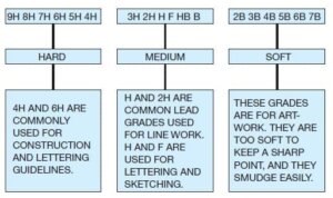
Lead grades of 2H and H are good in your automatic pencil for typical daily office use. The leads you select for line work and lettering depend on the amount of pressure you apply and other technique factors. Experiment until you identify the leads that give the best line quality. Leads commonly used for thick lines range from 2H to F, whereas leads for thin lines range from 4H to H, depending on individual preference.
Construction lines for layout and guidelines are very lightly drawn with a 6H or 4H lead. The Figure shows the different lead grades.
Compasses
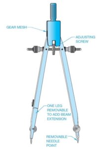
There are several basic types of compasses. A bow compass, shown in Figure, is used for most drawing applications. A beam compass consists of a bar with an adjustable needle, and a pencil or pen attachment for swinging large arcs or circles. Also available is a beam that is adaptable to the bow compass. This adapter works only on a bow compass that has a removable leg.
DIVIDERS
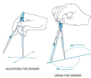
A functional divider should not be too loose or tight. It should be easy to adjust with one hand. You should always control a divider with one hand as you layout equal increments or transfer dimensions from one feature to another. Do not try to use a divider as a compass. The Figure shows how to handle the divider when used.
Proportional Dividers
Proportional dividers are used to reduce or enlarge an object without having to make mathematical calculations or scale manipulations. The centre point of the divider is set at the correct point for the proportion you want. Then you measure the original size line with one side of the proportional divider; the other side automatically determines the new reduced or enlarged size.
PARALLEL BAR
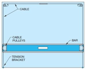
The parallel bar slides up and down a drafting board to allow you to draw horizontal lines. Use triangles with the parallel bar to draw vertical lines and angles. The parallel bar was common for architectural drafting because architectural drawings are frequently very large. Architects
using manual drafting often need to draw straight lines the full length of their boards, and the parallel bar is ideal for such lines.
TRIANGLES
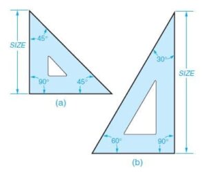
Triangles can also be used as straightedges to connect points for drawing lines without the aid of a parallel bar or machine scale. Use triangles individually or in combination to draw angled lines in 15 increments Also available are adjustable triangles with built-in protractors that are used to make angles of any degree up to a 45 angle.
TEMPLATES
Manual drafting templates are plastic sheets with accurate shapes cut out for use as stencils to draw specific shapes. The most common manual drafting templates are circle templates for drawing circles and arcs. Templates for drawing other shapes, such as ellipses, and for letters are also common. Templates are also available for specific requirements and drafting disciplines. For example, use architectural templates to draw the floor plan and other symbols to scale. Electronic drafting templates have schematic symbols for electronic schematic drawings.
Circle Templates
Circle templates are available with circles in a range of sizes beginning with 1/16 in. (1.5 mm). The circles on the template are marked with their diameters and are available in fractions, decimals, or millimetres. Figure 2.10 shows the parts of a circle. A popular template is one that has circles, hexagons, squares, and triangles.
Always use a circle template rather than a compass. Circle templates save time and are very accurate. For best results, when making circles, keep your pencil or pen perpendicular to the paper. To obtain proper width lines with a pencil, use a 0.9 mm automatic pencil.
Ellipse Templates
An ellipse is a circle seen at an angle. Isometric circles are ellipses aligned with the horizontal right or left planes of an isometric box. Isometric ellipse templates automatically position the ellipse at the proper angle of 35 16′.
IRREGULAR CURVES
Irregular curves, commonly called French curves, are curves that have no constant radii. A radius curve is composed of a radius and a tangent. The radius on these curves is constant and ranges from 3 ft to 200 ft. (900-60,000 mm). Irregular curves are commonly used in highway drafting. Ship’s curves are also available for layout and development of ships hulls. The curves in a set of ship’s curves become progressively larger and, like French curves, have no constant radii. Flexible curves are also available that allow you to adjust to the desired curve.
DRAFTING MACHINES
A manual drafting machine is a machine that mounts to the table or board and has scales attached to an adjustable head that rotates for drawing angles. When locked in a zero position, the scales allow drawing horizontal and vertical lines and perpendicular lines at any angle orientation. The drafting machine vernier head allows you to measure angles accurately to 5′ (minutes). Drafting machines, for the most part, take the place of triangles and parallel bars. The drafting machine maintains a horizontal and vertical relationship between scales, which also serve as straightedges. A protractor allows the scales to be set quickly at any angle.
There are two types of drafting machines: arm and track. The track machine generally replaced the arm machine in the history of manual drafting. A major advantage of the track machine is that it allows the drafter to work with a board in the vertical position. A vertical drafting surface position is generally more comfortable to use than a horizontal table. When ordering a drafting machine, the specifications should relate to the size of the drafting board on which it is mounted. For example, a 37½ 3 60 in. (950-1500 mm) machine properly fits a table of the same size.
Arm Drafting Machine
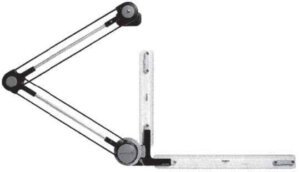
Track Drafting Machine
A track drafting machine has a traversing arm that moves left and right across the table and a head unit that moves up and down the traversing arm. There is a locking device for both the head and the traversing arm. The shape and placement of the controls of a track machine vary with the manufacturer, although most brands have the same operating features and procedures.
SCALES
A scale is an instrument with a system of ordered marks at fixed intervals used as a reference standard in measurement. A scale establishes a proportion used in determining the dimensional relationship of an actual object to the representation of the same object on a drawing. Use specific scales for mechanical, architectural, civil, and metric drawings.
Manual drafters use scales as measurement instruments to help create scaled drawings. In a CADD work environment, a scale is useful for sketching and taking measurements, as well as for related tasks. The scale is a universal and critical design and drafting concept.
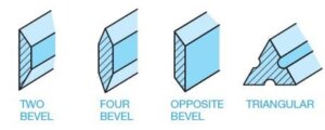
Scale Shapes
Drawing Scale
Drawings are scaled so that the objects represented can be illustrated clearly on standard sizes of paper. It would be difficult, for example, to make a full-size drawing of a house. You must decrease the displayed size, or scale, of the house to fit properly on a sheet. Another example is a very small machine part that requires you to increase the drawing scale to show necessary detail. Machine parts are often drawn full size or even two, four, or ten times larger than full size, depending on the actual size of the part.
The selected scale depends on:
- The actual size of the objects
- The amount of detail to
- The media size.
- The amount of dimensioning and notes
In addition, you should always select a standard scale that is appropriate for the drawing and drafting discipline. The drawing title block usually indicates the scale at which most views are drawn or the predominant scale of a drawing. If the scale of a view differs from that given in the title block, the unique scale typically appears as a note below the corresponding view.
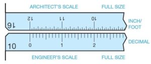
Mechanical Engineer’s Scale
DRAFTING MEDIA
The term media, as applied here, refers to the material on which you create drawings, such as paper or polyester film. The two main types of media used for manual drafting are vellum and polyester film, with vellum being the most commonly used. Several factors other than cost also influence the purchase and use of drafting media, including durability, smoothness, erasability, dimensional stability, and transparency.
Durability is a consideration if the original drawing will be extensively used. Originals can tear or wrinkle, and the images can become difficult to see if the drawings are used often. Smoothness relates to how the medium accepts line work and lettering. The material should be easy to draw on so that the image is dark and sharp without a great deal of effort on your part.
Erasability is important because errors need to be corrected, and changes are frequently made. When images are erased, ghosting-the residue that remains when lines are dif- ficult to remove-should be kept to a minimum. Unsightly ghost images reproduce in a print. Materials that have good erasability are easy to clean. Dimensional stability is the quality of the media to remain unchanged in size because of the effects of atmospheric conditions such as heat, cold, and humidity. Some materials are more dimensionally stable than others.
Reproduction
One thing most designers, engineers, architects, and drafters have in common is that their finished drawings are intended for reproduction. The goal of every professional is to produce drawings of the highest quality that give the best possible prints when reproduced. Many of the factors that influence the selection of media for drafting have been described; however, the most important factor in reproduction.
The primary combination that achieves the best reproduction is the blackest and most opaque lines or images on the most transparent base or material. Vellum and polyester film make good prints if the drawing is well done. If the only concern is the quality of the reproduction, ink on polyester film is the best choice. However, some products have better characteristics than others. Some individuals prefer certain products. It is up to individuals and companies to determine the combinations that work best for their needs and budgets.
SHEET SIZE AND FORMAT
STANDARDS
Most professional drawings follow specific standards for sheet size and format. The Australian Drafting Standard specifies the exact sheet size and format for engineering drawings created for the manufacturing industry. Other disciplines can follow Australian Drafting standards. However, architectural, civil, and structural drawings used in the construction industry generally have a different sheet format and may use unique sheet sizes, such as architectural sheet sizes. Follow sheet size and format standards to improve readability, handling, filing, and reproduction; this will also help ensure that all necessary information appears on the sheet.
When selecting a sheet size, consider the size of objects drawn; the drawing scale; the amount of additional content on the sheet, such as a border, title block, and notes; and drafting standards. In general, choose a sheet size that is large enough to show all elements of the drawing using an appropriate scale and without crowding. For example, the dimensioned views of a machine part that occupies a total area of 15 in. 3 6 in. (381 mm 3 153 mm), can typically fit on a 17 in. 3 11 in. (B size) or 420 mm 3 297 mm (A3 size) sheet.
DIAZO REPRODUCTION
Diazo prints are also known as ozalid dry prints and blue-line prints. The diazo reproduction process has been mostly replaced by photocopy reproduction and the use of CADD files for printing and plotting. Diazo printing uses a process that involves an ultraviolet light passing through a translucent original drawing to expose a chemically coated paper or print material under-neath. The light does not go through the dense, black lines on the original drawing, so the chemical coating on the paper beneath the lines remains. The print material is then exposed to ammonia vapour, which activates the remaining chemical coat-ing to produce blue, black, or brown lines on a white or colour-less background. The print that results is a diazo, or blue-line print, not a blueprint. The term blueprint is a generic term used to refer to diazo prints even though they are not true blueprints. Originally, the blueprint process created a print with white lines on a dark blue background.
PHOTOCOPY REPRODUCTION
Photocopy printers are also known as engineering copiers when used in an engineering or architectural environment. A photocopy printer is a machine for photographically reproducing material, especially by xerography. Xerography is a dry photographic or photocopying process in which a negative image formed by a resinous powder on an electrically charged plate is electrically transferred to and fixed as a positive image on a paper or other copying surface. Prints can be made on bond paper, vellum, polyester fi lm, coloured paper, or other translucent materials. The reproduction capabilities also include instant print sizes ranging from 45 percent to 141 percent of the original size.
Larger or smaller sizes are possible by enlarging or reducing in two or more steps. Almost any large original can be converted into a smaller-sized reproducible print, and then the secondary original can be used to generate additional photocopy prints for distribution, inclusion in manuals, or for more convenient handling. In addition, a random collection of mixed-scale drawings can be enlarged or reduced and converted to one standard scale and format. Reproduction clarity is so good that halftone illustrations (photographs) and solid or fine line work have excellent resolution and density.
The photocopying process and CADD printing and plotting have mostly replaced the diazo process. Photocopying has many advantages over diazo printing, including quality repro-duction in many sizes, use of most common materials, and no hazardous ammonia. A CADD system allows you to produce a quality hard copy print quickly. A hard copy is a physical drawing produced by a printer or plotter. The hard copy can be printed on vellum for further reproduction using the diazo or photocopy process.
PROPERLY FOLDING PRINTS
Prints come in a variety of sizes ranging from small, 8½ 3 11 in., to 34 3 44 in. or larger. It is easy to fi le the 8½ 3 11 in. size prints because standard file cabinets are designed to hold this size. There are file cabinets available called flat files that can be used to store full-size unfolded prints. However, many companies use standard file cabinets. Larger prints must be properly folded before they can be filed in a standard file cabinet. It is also important to fold a print properly if it is to be mailed.
Folding large prints is much like folding a road map. Folding is done in a pattern of bends that results in the title block and sheet identifi cation ending up on the front. This is desirable for easy identifi cation in the file cabinet. The proper method used to fold prints also aids in unfolding or refolding prints.
MICROFILM
Microfilm is photographic reproduction on film of a drawing or other document that is highly reduced for ease in storage and sending from one place to another. When needed, equipment is available for enlargement of the microfi lm to printed old vellum becomes yellowed and brittle. In addition, in case of a fire or other kind of destruction, originals can be lost and endless hours of drafting vanish. For these and other reasons, microfilm has been used for storage and reproduction of original drawings. Although microfilm storage of old drawings still exists in some companies, CADD files have replaced the use of microfilm for most modern applications.
CADD VERSUS MICROFILM
Microfilm was once an industry standard for storing and accessing drawings. Large international companies especially relied on the microfilm network to ensure that all worldwide subcontractors, vendors, clients, and others involved with a project were able to reproduce needed draw-ings and related documents. One advantage of microfilm was the ability to archive drawings-that is, store some-thing permanently for safekeeping.
The use of CADD in the engineering and construction industries has made it possible to create and store drawings electronically on a computer, optical disk, or other media. This makes it possible to retrieve stored drawings easily and quickly. A big advantage of CADD file storage involves using CADD drawings. When you retrieve CADD-generated drawings, they are of the same quality as when they were originally drawn. You can use CADD drawings to make multiple copies or to redesign a product efficiently. In addition to the maintained original quality of the stored CADD drawing, the drawing file can be sent anywhere in the world over the Internet or within a company’s intranet. The Internet is a worldwide network of communication between computers, and intranet links computers within a company or an organization.
CAD/CAM
The optimum efficiency of design and manufacturing methods is achieved without producing a single paper copy of a drawing of a part. Computer networks can directly link engineering and manufacturing departments by integrating computer-aided design (CAD) and computer-aided manufacturing or machining (CAM) software. This integration is referred to as CAD/CAM. The drafter or designer creates a 3-D model or 2-D engineering drawing of a part using CADD software. CAM software is then used to convert the geometry to computer numerical control (CNC) data that is read by the numerically controlled machine tools. Often, the CAD/CAM system is electronically connected to the machine tool. This electronic connection is called networking. This direct link is referred to as direct numerical control (DNC), and it requires no additional media such as paper, disks, CDs, or tape to transfer information from engineering to manufacturing.
Australian Design & Drafting Services provide excellent service for CAD Design and Drafting. Contact Us for more info
What are the equipments in drafting?
In traditional drafting, several essential tools and equipment are commonly used:
Drawing Board: A flat, smooth surface on which paper is attached for drawing.
Drafting Table: A specialized table with adjustable height and angle, designed for comfortable drafting work.
Drafting Machine: Attaches to the drawing board or drafting table, enabling precise drawing angles and measurements.
T-Square: A T-shaped ruler used to draw horizontal lines. One edge of the T-square rests against the edge of the drawing board for accuracy.
Triangles: Triangular rulers used to draw vertical and diagonal lines. Common types include 30-60-90 and 45-45-90 triangles.
Compasses: Used for drawing circles and arcs with precision.
Drafting Pencils: Mechanical pencils with various lead thicknesses (e.g., 0.3mm, 0.5mm, 0.7mm) for drawing lines of different weights.
Eraser Shield: A small metal or plastic template with various hole sizes to shield parts of the drawing while erasing.
Erasing Tools: Erasers of different types, including kneaded erasers for gentle removal of graphite without smudging.
Scale Ruler: A ruler with multiple scales for accurately measuring distances on the drawing.
Templates: Pre-made shapes such as circles, squares, and ellipses for consistent drawing.
Drawing Paper: High-quality paper suitable for drafting work, usually in standard sizes like A4 or A3.
Drafting Brushes: Used to remove eraser shavings and other debris from the drawing surface.
Drafting Tape: Low-tack adhesive tape used to secure the paper to the drawing board without damaging it.
Light Table: A backlit surface that allows tracing of drawings and overlays for precise alignment.
What is the instrument used for measuring in manual drafting?
In manual drafting, one of the primary instruments used for measuring is the scale ruler. Scale rulers come in various types, including:
Architect’s Scale: Designed for architectural drafting, an architect’s scale typically has multiple scales on each edge, allowing measurements in different units such as feet, inches, and fractions of an inch.
Engineer’s Scale: Engineer’s scales are commonly used in engineering and technical drafting. They usually feature scales for measurements in decimal inches or millimeters.
Metric Scale: These scale rulers are calibrated in metric units, such as millimeters or centimeters, and are used for drafting in countries that primarily use the metric system.
Civil Engineering Scale: Similar to the architect’s scale but tailored for civil engineering applications, this scale ruler often includes specialized scales for measuring distances on maps, blueprints, or technical drawings.
