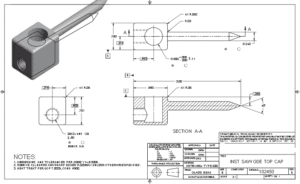
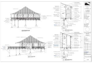
Engineering drawing is a common language that describes the process of creating drawings for engineering and architectural application. The engineering drawings work the best and accept standards and format.
It offers an efficient way to communicate and use specific data with adding design intent. The Engineering drawings do not require work and interpret of others’ drawings. It comes with decorative drawings along with using artistic paintings. Using a successful engineering drawing, the user can describe a specific item that the drawing viewer understands without misinterpretation.
One can talk about the term engineering drawing, known for its Drafting, mechanical drawing, mechanical Drafting, engineering drafting, technical Drafting and technical drawing. The Drafting comes with a different graphic language that uses lines, symbols, and other notes to describe objects for an industry like manufacturing or construction. There are technical disciplines that use Drafting, covering civil, architecture, electrical engineering, electronics, piping, manufacturing, and structural engineering.
The term mechanical drafting comes with alternate meanings. The manufacturing industry comes with mechanical Drafting, where the name is derived from mechanisms. The construction industry uses mechanical Drafting in terms of drafting heating, ventilating, and air-conditioning (HVAC) systems. It comes with a mechanical portion of an architectural project.
Whereas if we talk about manual Drafting, it’s a term that describes traditional drafting practice, including pencil or ink onto a medium. It covers paper or polyester film, which supports drafting instruments and equipment. Computer-aided Drafting (CAD) has taken the place of manual Drafting, where the CAD uses computers for drafting. CAD also refers to computer-aided design when computers are used to design.
ENGINEERING DRAWING
Engineering drawings add various concepts that cover instructions, engineering requirements, and proposals. It comes with multiple people and includes different individuals involved with a project. An engineering drawing comes with a complete set of engineering designs that offer data needed to manufacture an item or product. It includes machine parts, consumer products and many more structures.

The drawing study covers medical instruments that completely describe all geometric features’ location and size. Later, it identifies the characteristics of the part. It mainly uses the material along with manufacturing precision. Also, the medical instrument company uses the drawing to share the document design, which intends to be a part of manufacturing. Let’s say how difficult it can be to understand the engineering drawing.

Actually, the engineering drawing comes with an architectural drawing that is mainly used for home re-modelling projects. The drawing uses one sheet in a set of communication with architectural style, size, and location with building features and taking care of the construction methods and materials.
The drawing offers sheets that communicate architectural style, the size and location of building features, and construction methods. The drawings are set to obtain to pay for construction, make permits and legally begin construction. It offers accurate cost estimates that bring impossible and impractical construction without engineering drawings.
Computers In Design and Drafting
The computers offer revolutionised business along with adding industry process. It covers design and drafting practices with ease. Computer-aided design and drafting (CADD) is a process that uses a computer with CADD software for design and drafting applications. Also, the software is a program that enables a computer to perform specific functions and accomplish a task. Talking CAD is the acronym for computer-aided design, referred to as computer-aided Drafting.
Computer-aided design and computer-aided Drafting offer specific aspects of the CADD process. It mainly uses CADD for the design and drafting process to get accurate and faster CAD design. Several industries mostly use engineering and architecture to get a better outcome. Most engineering industries and educational institutions use manual drafting practices that evolved to CADD.
Whereas CADD allows drafters and designers to produce accurate drawings with neat and matched industry standards. CADD makes architectural drawings with artistic flair lettering and line styles, including a matched appearance with the finest handwork available. In addition to this, CADD drawings come consistently from one person or company to the next. It supports enhancing the ability of designers and drafters, adding creativity to it. It uses new tools such as solid modelling, animation, and virtual reality.
We are an excellent Australian Design & Drafting Service company that provides the best CAD Design and Drafting. Contact Us to get more information.
What is basic engineering drawing?
Basic engineering drawing refers to the fundamental principles and techniques used to create clear, accurate, and standardized drawings that convey technical information effectively. These drawings serve as a visual representation of objects, components, or structures, and they are essential for communication, documentation, and manufacturing processes in engineering disciplines such as mechanical, civil, electrical, and architectural engineering.
Here are some key aspects of basic engineering drawing:
Orthographic Projection: This is the primary method used to represent objects in engineering drawings. It involves creating multiple 2D views of an object from different perspectives (front, top, side, etc.) to fully describe its shape and features.
Dimensioning: Dimensions are added to engineering drawings to specify the size and location of features accurately. This includes linear dimensions (length, width, height), angular dimensions (angles), and geometric dimensions (tolerances, concentricity, symmetry, etc.).
Drawing Standards: Basic engineering drawings adhere to standardized conventions and symbols to ensure consistency and clarity. Common standards include ASME Y14.5 for dimensioning and tolerancing, ISO 128 for technical drawings, and specific industry standards as needed.
Line Types and Weights: Different types of lines (e.g., continuous, dashed, hidden) and line weights are used to differentiate between different elements of the drawing, such as object lines, dimension lines, and centerlines.
Title Block: Each engineering drawing typically includes a title block containing essential information such as the drawing title, scale, revision history, author, and date.
Symbols and Notations: Symbols and abbreviations are used to represent specific features, materials, processes, and annotations on engineering drawings. These symbols help convey information concisely and universally.
Scale: Drawings may be drawn to scale to represent objects accurately relative to their actual size. Common scales include full scale (1:1), half scale (1:2), and so on.
What are engineering drawings used for?
Engineering drawings serve as the universal language of engineers, architects, and designers. They are used for several purposes:
Communication: Engineering drawings communicate the design intent and specifications to various stakeholders involved in the manufacturing or construction process. This includes engineers, fabricators, machinists, contractors, and inspectors.
Visualization: They provide a visual representation of the final product, enabling stakeholders to understand how the object or structure will look and function.
Documentation: Engineering drawings document the design, dimensions, materials, tolerances, and other critical information necessary for manufacturing or construction. They serve as a reference throughout the lifecycle of the product or project.
Quality Control: Manufacturers use engineering drawings to ensure that the final product meets the required standards and specifications. They serve as a basis for quality control checks and inspections.
Legal and Regulatory Compliance: In regulated industries such as aerospace, automotive, and construction, engineering drawings are essential for complying with legal and regulatory requirements. They demonstrate that the product or structure meets safety, environmental, and other regulatory standards.
Modification and Maintenance: Engineering drawings are used for maintenance, repair, and modification purposes. They provide guidance on how to disassemble, repair, or modify a product or structure without compromising its integrity.
Cost Estimation: By providing detailed information about the design and materials, engineering drawings help in estimating the cost of manufacturing or construction accurately.
