Australian Design and drafting Services

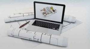
Do you know, how much it cost to design a home? Here, the answer is quite simple. All you require to do is to outsource ASTCAD Design & Drafting. It helps to avail of cutting-edge 2D design drafting solutions for Australia, without investing in expensive technology or going through tedious recruitment headaches. Below, we have listed the importance of effective 2D drafting and the varied types of 2D drafting services that offer numerous benefits that come with outsourcing to ASTCAD Design & Drafting.

If your firm drawing is designed for a home, office, restaurant, or other type of building, you should be aware of its critical role. The 2D drafting offers a successful outcome of a building. 2D drafting is one step ahead that cannot afford to skip, even though you may encounter other problems while designing. Furthermore, 2D drafting provides time, skill and expertise. Using outsourcing, you need not to worry about 2D drafting anymore. You have to outsource 2D drafting to Australian Design & Drafting along with enjoying big savings on cost, time and effort.

How to reduce design and drafting cost?

No matter what type of design plan you’re looking for, you can avail an effective 2D drafting plan. Outsource to ASTCAD Design & Drafting using best mechanical engineers and 2D drafters. Put your skills and knowledge with delivering a cutting-edge 2D draft for your building. Avail 2D drafting services for the following:

  • Architectural drawings
  • Preliminary drawings
  • Millwork drawings
  • Assembly drawings
  • Shop drawings
  • Structural design drawings
  • Engineering (MEP) drawings
  • Presentation drawings
  • Machine drawings
  • Manufacturing drawings
  • Fabrication drawings
  • Structural steel detailing
  • Construction or working drawings

Here’s Why ASTCAD Design & Drafting Is the Preferred Outsourcing For 2D Design Drafting:

  1. Choose the latest 2D drafting software and tools that offer ASTCAD Design & Drafting by employing the latest 2D drafting tools such as, AutoCAD®, MicroStation®, SolidWorks®, Staad Pro®, Ansys®, 3DS Max®, VRay, X-Steel, Revit®, ProE®, Autodesk® Inventor®, CATIA®, and Unigraphics/NX to create world-class 2D drafts.
  2. Skilled 2D drafters: Outsource 2D drafting to ASTCAD Design & Drafting. It gives an access to a dedicated engineers and drafters team by collaborating with your company. We understand your needs and provide satisfactory 2D drafting solution. Our excellent team uses a 2D drafting solution used as preliminary drawing. Therefore, it includes architectural drawing, structural drawing, that develop a firm base for your design plans.
  3. 2D drafting in CAD: ASTCAD Design& Drafting provides an extensive knowledge of 2D drafting in CAD. It is based on exact scaling and specifications that one need to get.
  4. Huge cost savings: Simply cutting down on current cost by 50% while getting access to professionally drawn 2D drafts to meet your expectations.

Outsource to ASTCAD Design & Drafting, and work with the best people in the industry. It uses 2D drafting out of your hands and focus on your design plans. We offer dedicated team of skilled mechanical engineers that use ASTCAD Design & Drafting. It works out a 2D draft for your building ahead of your deadline.

Outsource 2D drafting to ASTCAD Design & Drafting with experiencing freedom from mundane recruitment, payroll or infrastructure-related hassles.

Which 2D drafting service would you prefer if you’re looking to outsource? Have you outsourced 2D drafting before? If yes, how did it went? If you have a question outsource or express your views. Leave your comment in the box below. We, at ASTCAD Design & Drafting, love to hear from you.

Is drafting and design a good career?

rafting and design can be a rewarding career for those who enjoy creative problem-solving, technical drawing, and bringing ideas to life through visualization. Here are some factors to consider when determining if it’s a good fit for you:
Interest and Passion: If you have a genuine interest in design, architecture, engineering, or related fields, drafting and design can be a fulfilling career path.
Skills and Abilities: Strong spatial reasoning, attention to detail, and proficiency with design software are essential skills for drafters and designers. If you enjoy working with CAD (Computer-Aided Design) software and have a knack for precision, this career might be a good fit.
Job Opportunities: The demand for drafters and designers varies by industry and location, but there are typically opportunities in architecture, engineering, manufacturing, construction, and other sectors. Research the job market in your area to gauge the demand for drafting and design professionals.
Career Growth: With experience and additional training, drafters and designers can advance to more senior roles, such as lead drafter, CAD manager, or design engineer. Continuous learning and staying updated on industry trends and technologies are essential for career growth in this field.
Work Environment: Drafters and designers may work in a variety of settings, including architectural firms, engineering companies, construction companies, manufacturing facilities, and government agencies. Consider the type of work environment that aligns with your preferences and lifestyle.
Job Stability and Compensation: While the salary and job stability for drafters and designers can vary depending on factors like experience, location, and industry, many professionals find stable employment with competitive salaries and benefits.

What is drafting and design technology?

Drafting and design technology refers to the use of various tools, techniques, and software applications to create technical drawings, schematics, and plans for the purpose of visualizing and communicating design concepts. This field encompasses a range of industries, including architecture, engineering, manufacturing, construction, and product design.
Here are some key aspects of drafting and design technology:
Technical Drawing: Drafting involves the creation of detailed, precise drawings that communicate the dimensions, specifications, and other relevant information of a design. This can include architectural drawings, mechanical drawings, electrical schematics, and more.
Computer-Aided Design (CAD): CAD software allows designers and drafters to create and manipulate digital drawings and models with greater efficiency and precision compared to traditional hand-drawing methods. CAD software is widely used in drafting and design across various industries.
3D Modeling: In addition to 2D drawings, drafting and design technology often involves the creation of 3D models using CAD software. 3D modeling allows designers to visualize designs from different angles, simulate real-world conditions, and detect potential issues before construction or manufacturing begins.
Building Information Modeling (BIM): BIM is a process that involves creating and managing digital representations of physical and functional characteristics of places. It enables collaboration among architects, engineers, contractors, and other stakeholders throughout the entire lifecycle of a building or infrastructure project.
Drafting Standards and Practices: Drafting and design technology requires adherence to industry-specific standards and practices to ensure the accuracy, consistency, and compatibility of drawings and designs. This includes standards for dimensioning, notation, symbols, and file formats.
Collaboration and Communication: Effective communication and collaboration are essential in drafting and design projects, as designers often work closely with engineers, architects, clients, and other stakeholders to develop and refine designs.

By using 3D modelling over the past 20 years, we have improved our engineer’s ability to design, model, and fabricate complex parts for various industries. It covers automotive, aerospace, and biomedical. Let’s say a tool that helps civil engineers, city planners, and construction crew to plan out networks for water distribution and wastewater management operations using a single mouse click. Such tools are readily available today and assist us in complex optimizations.

CAD Modeling helping

If we talk about network engineering, then they are a design of pressurized pipelines that is highly complex and require significant planning and understanding. It helps in regulations and design criteria. It is a highly time-consuming task that requires significant effort and prior knowledge with time.

Even with prior understanding, it offers cumbersome to meet the necessary design criteria. It includes a minimum pipeline slope, spacing between valves, and intersection with existing utilities. Along with adding other applicable quality standards to it.

DESIGN AND OPTIMISATION TOOLS FOR BETTER WATER INFRASTRUCTURE

Consider that your design comes with a water network along with a bottom-up approach. It uses the available water source and adds information on the constituent and tank-mixing in the design. Also, in such a scenario, the common questions might be:

  • How would the water system handle a fire?
  • What is the limitation of design in your water network?
  • Will there be enough water at each fire hydrant?
  • What happens if there comes excess flow from a particular location?
  • Will there be a sufficient flow of water that handles your system requirements?

CAD Modeling helping

The CAD programs use 3D modelling designed with complex water distribution systems. It provides the answer to the above questions. Bentley System’s Water GEMS runs a stand-alone tool with MicroStation or AutoCAD tools. The Pipe Plan and Innovyze’sInfoWate tools offer a similar solution to it. The above tools are adopted by utility companies, municipalities, townships, and design engineers. They provide efficient design and optimization tools for water infrastructure and networks.

What are the advantages of using CAD to develop water distribution networks?

  • It comes with the ability to visualise the network in a 3D environment.
  • It offers the ability to model pipe pressures.
  • It helps in GPS tagging of the pipe network and existing pipes.
  • It allows designers to determine points of interference and avoid critical problem areas.
  • It has the ability to model-flow rate, loss nodes and pressures.
  • It is mainly used to design for high-flow conditions at a fire, which requires fire hydrants.

CAD REAL-TIME EXAMPLES AND ITS USE IN WATER DISTRIBUTION NETWORKS

The CAD tools are most likely to be used in civil engineering planning and design. Salt Lake City is used in Utah, and Huntington Beach in California are the two cities that have adopted WaterGEMS software for designing, optimising, and maintaining their water distribution networks. Salt Lake City’s water distribution network helps to serve almost half a million residents, including over 1,000 miles of pipes.

It uses a complete geographical information system (GIS) for its water, sewer, and stormwater infrastructure. It is built into a model. It primarily uses WaterGEMS, a city currently building a hydraulic model for the water distribution system. It primarily uses existing data to update and maintain the city’s expansion.

The tool mainly determines the optimal pipes that replace pipes. Some customers complained that the flow was insufficient during peak periods. They use guidance where the city can remediate the complaints. Further, they meet the fire department’s flow requirement with 1500 gallons per minute for all fire hydrants along with high pressure.

CAD Modeling helping

BEST KNOWN CAD TOOLS FOR OPTIMISATION AND PIPING PLANS

WaterGEMS:

WaterGEMS is a tool used primarily to design, analyse, and optimise water distribution systems. Several features are used, such as WaterGEMS, covering steady-state and extended-period simulations. Along with constituent-concentration Analysis, source tracing, tank-mixing, water-age, and fire-flow analyses.

Additionally, there are controls used to rule-based logic and pumps for single or variable speed. The tools help users find operational bottlenecks by minimising energy consumption and modelling real-time operations. The critical Analysis is another essential feature that allows users to find the weak links and valves in the water distribution system.

The tool provides the ability to import CAD, GIS, database data and perform the polyline-to-pipe conversion from DXF files. The program includes optimisation tools that facilitate and enhance design iterations. It is more impressive that the program can directly link to Supervisory, Control, and Data Acquisition (SCADA) systems. It was named as SCADAConnect. Here the software tool provides an environment to monitor and control the network in real-time. They use the tool along with the pipe network model monitored in real-time. It allows a comparison of the model with the operation. The problem deficiencies investigate and evaluated using forensic performance analysis.

PipePlan: 

A second tool comes with a similar utility called Innovyze’s PipePlan software. It provides a geospatial environment for water network analysis. It was designed for a detailed hydraulic network model. The design engineers produce and validate distribution and transmission line designs iteratively with minimal effort.

PipePlan allows horizontal and vertical alignments that help to define the location of pipe fittings such as bends, air valves, washouts, end caps and tees. It comes with an essential feature of the tool and its interference checking. It comes with automating report intersection with existing/proposed utility networks.

CONCLUSIONS

The tool maintains water distribution networks and goes through the challenging task for governments across the globe. In this context, the CAD software plays a significant role in enabling the proper water flow regulation. Also, it covers cities and urban areas that would continue to expand. Therefore, the tools like WaterGems and PipePlan comes with an even more critical role in providing efficient design and optimized water networks in the future.

What is CAD modeling used for?

CAD (Computer-Aided Design) modeling is used across various industries for a wide range of purposes. Here are some of the key applications of CAD modeling:
Product Design and Development: CAD modeling is extensively used in product design and development across industries such as automotive, aerospace, consumer electronics, and industrial equipment. Designers use CAD software to create detailed 3D models of products, allowing them to visualize concepts, iterate designs, and simulate performance characteristics before manufacturing.
Architectural Design: Architects and architectural firms use CAD modeling to create detailed 2D plans and 3D models of buildings, structures, and interior spaces. CAD software enables architects to explore different design options, communicate design ideas to clients and stakeholders, and generate construction documents with accurate dimensions and specifications.
Engineering Design and Analysis: CAD modeling is integral to engineering design and analysis processes in disciplines such as mechanical, electrical, civil, and structural engineering. Engineers use CAD software to design complex components, assemblies, and systems, perform simulations and analyses (such as stress analysis, fluid flow analysis, and thermal analysis), and optimize designs for performance, reliability, and manufacturability.
Manufacturing and Prototyping: CAD models are used in manufacturing processes to create tooling, molds, and fixtures, as well as to program computer-controlled machining equipment (CNC machines) for precision manufacturing. CAD models can also be used to create prototypes through techniques such as 3D printing, allowing designers and engineers to validate designs and test functionality before mass production.
Construction and Building Information Modeling (BIM): CAD modeling is central to building design and construction processes, enabling architects, engineers, and contractors to collaboratively design, visualize, and manage building projects. Building Information Modeling (BIM) platforms use CAD models to create digital representations of buildings and infrastructure, facilitating coordination, clash detection, and efficient project management throughout the lifecycle of a project.
Simulation and Visualization: CAD models can be used for simulation and visualization purposes in various fields. For example, CAD models are used in virtual reality (VR) and augmented reality (AR) applications for immersive visualization and walkthroughs of designs. CAD models can also be used for marketing purposes, allowing companies to showcase products or architectural designs in promotional materials or presentations.

How to do CAD Modelling?

CAD (Computer-Aided Design) modeling involves using specialized software to create detailed digital representations of objects, components, buildings, or systems in a virtual environment. Here’s a general overview of the steps involved in CAD modeling:
Select CAD Software: Choose a CAD software program that suits your needs and the requirements of your project. Popular CAD software options include AutoCAD, SolidWorks, Autodesk Inventor, CATIA, and Fusion 360, among others. Consider factors such as features, compatibility, ease of use, and cost when selecting software.
Create a New File: Start a new project or file in your chosen CAD software. Set up the file with the appropriate units of measurement and any other project-specific settings.
Sketch Geometry: Begin by sketching the basic geometry of the object or component you want to model. Use tools such as lines, circles, arcs, rectangles, and polygons to create 2D sketches that represent the shape and dimensions of your design.
Apply Constraints and Dimensions: Apply geometric constraints (e.g., parallel, perpendicular, concentric) and dimensions to your sketches to ensure they meet design requirements and remain fully defined. Constraints and dimensions help maintain the parametric nature of the model, allowing you to make changes later in the design process.
Create Features: Use a variety of modeling tools to create 3D features from your 2D sketches. Common features include extrusions, revolves, sweeps, lofts, fillets, chamfers, holes, and patterns. These features add depth and complexity to your model and allow you to represent real-world objects more accurately.
Refine and Modify: Refine your model by adding detail, adjusting dimensions, and making modifications as needed. Use editing tools to move, rotate, scale, or delete geometry, and apply modifications to individual features or the entire model.
Assemble Components (if applicable): If your design involves multiple parts or components, use assembly features to bring them together in a virtual assembly. Position, align, and constrain components relative to each other to create an accurate representation of the final product or system.
Check for Errors: Use built-in analysis tools or add-ons to check your model for errors, such as gaps, overlaps, or interference between components. Fix any issues to ensure the model is structurally sound and manufacturable.
Document and Annotate: Add annotations, dimensions, labels, and other documentation to your model to communicate design intent and provide information for manufacturing, assembly, and inspection purposes.
Export or Share: Once your CAD model is complete, you can export it in various file formats for sharing, collaboration, or further processing. Common file formats include .dwg, .step, .iges, .stl, and .pdf.

CAD in Product Development

CAD in Product Development – CAD and CAM are industrial computer applications, which have greatly reduced the time and cost cycles between initial concepts and product development. They have enabled designers and manufacturers to make significant cost savings. These tools also reduce the time to market for new products, and reduce the number of design flaws, which tend to hamper productivity, and in some cases ground an entire production cycle. Since the 1980s, CAD and CAM have provided exponential gains to both the quantity and quality of products.[/fusion_text][fusion_text]The primary advantages of CAD include the ability to:

  • reduce design cycle times
  • design a complex machine without the need to prototype
  • prototype parts directly from a CAD model
  • reduce low-cost design iterations rapidly
  • alter the designs quickly by changing geometrical parameters
  • view designs or parts under a variety of representations
  • virtually simulate real-world applications

CAM is the use of CAD data to control automated machinery for producing parts designed using CAD. The benefits of linking part fabrication directly to the CAD model include:

  • Direct control of computer numerical control (CNC) or direct numerical control (DNC) systems to produce exact replicas of the designs
  • Ability to skip the engineering drawing phase
  • Reduced part variability

How Boeing Set the Standard for Design Automation? – Cad Importance in Product Development –

Boeing is the world’s second-largest defence contractor and a leading manufacturer of aircraft, rockets, and satellites. CAD has played a major role in their product development planning and operations over the past three decades. Boeing announced the development of the 777 in the late 1980s, leading many aviation experts to question their decision. The design of an entirely new aircraft is a highly expensive task, whereas the success of the 747 models had been serving customers for over 30 years led experts to believe that the proper solution was to modify the 747 to suit passenger needs. Boeing applied a new approach that included customer inputs in the design phase from several major airlines, including United Airlines, Nippon Airways, British Airways, Japan Airlines and Cathay Pacific.

More importantly, Boeing invested over $1 billion in design automation using CAD based on CATIA (Computer Aided Three-dimensional Interactive Application) and ELFINI (Finite Element Analysis System) to design the new airliner that would turn out to become an industry standard. Both of these software packages were developed by Dassault Systemes of France. Boeing applied the following objectives to guide their break-through process:

  • Reduce aircraft development time significantly
  • Meet customer requirements better by involving them in the development process
  • Eliminate costly modification procedures

As a result, the 777 was the first aircraft in the world to be designed entirely using CAD technology. It was designed to maximize efficiency and quality. The completed design included over 3 million parts! The design process, its innovative features, and Boeing’s approach to manufacturing became the “Gold Standard” for development of future aircraft and were applied to a number of other projects, such as the International Space Station. The design was executed so successfully that a full-scale mock-up of the 777 was never built and was not necessary, reducing the design and production time. In fact, its first flight was so successful that the design was considered one of the most seamless and smoothest to date.

By using CAD models, design engineers were able to provide “built-in” options, which did not need to go to production, such as folding wing-tips. By developing options in CAD, the cost associated with such a trade study and its design is minimized.

What Benefits did Boeing Realize by Automating its Design Process? – Cad Importance in Product Development –

To assess the value of the design automation that Boeing implemented in their process by using 3D CAD modelling to design the 777, Boeing compared the effort with their previous design efforts (757 and 767). Overall, they realized:

  • 91% reduction in development time
  • 71% reduction in labour costs
  • Over 3000 assembly interfaces were developed virtually without the need for prototypes
  • Reduction in design and production flaws, mismatches, and associated errors
  • 90% reduction in engineering change requests from approximately 6000 to 600
  • 50% reduction in cycle time for engineering change request
  • 90% reduction in material rework
  • 50 times improvement in assembly tolerances for the fuselage.

It is notable that the design was completed at a time when CAD was not linked directly with FEA and CFD modelling software, but the effort has still been widely accepted as one of the greatest uses of CAD of its time.

Importance of CAD in Product Development

The value of CAD modelling is just as valuable on a smaller scale, such as in the bicycle industry. For example, Cannondale is another pioneer that has utilized CAD and CAM technology since the 1990s to reduce its production cycle and reduce manufacturing costs, resulting in significantly higher production rates. As part of their integrated system design approach, Cannondale extended its production capability to produce custom designs for customers that are fit to their individual needs, resulting in over 7000 custom-fit designs that can be produced using their vertical integration production strategy. Their highly advanced model allows the company to maintain a competitive advantage in all aspects of design, performance, and production.

What Lessons can be Learnt from these Pioneers?

  • Leverage customer input early in the design process
  • Use CAD, CAM, and rapid prototyping of models to obtain valuable feedback from all stakeholders, including end customers, manufacturers, and suppliers
  • Reduce design times by applying CAD early in the design process no matter how small, simple, or complex your design.

What is concept to product development?

Concept to product development is the process of transforming an initial idea or concept into a tangible, marketable product. It involves several stages, each of which contributes to refining and shaping the idea until it becomes a finished product ready for sale. Here’s an overview of the typical stages involved:
Idea Generation: This is the starting point where concepts are brainstormed, researched, or identified based on market needs, consumer preferences, technological advancements, or other sources of inspiration.
Concept Development: Once an idea is generated, it’s essential to flesh it out into a more detailed concept. This involves outlining the product’s features, benefits, target audience, and potential market positioning.
Market Research: Conducting market research is crucial to validate the concept and gather insights into consumer needs, preferences, and behaviors. This helps in refining the concept to better align with market demands.
Design and Engineering: In this stage, the concept starts taking shape through design and engineering efforts. Designers create visual representations of the product, while engineers work on the technical aspects, ensuring feasibility and functionality.
Prototyping: Prototyping involves creating early-stage versions of the product to test its design, functionality, and user experience. Prototypes can be physical (e.g., 3D printed models) or digital (e.g., software prototypes).
Testing and Iteration: Prototypes are tested extensively to identify any flaws, usability issues, or areas for improvement. Feedback from testing is used to refine the product through iterative design cycles.
Manufacturing and Production: Once the design is finalized and prototyping is complete, the product moves into the manufacturing phase. This involves setting up production processes, sourcing materials, and manufacturing units to produce the final product at scale.
Quality Assurance: Quality assurance processes ensure that the manufactured products meet specified standards and requirements. This involves rigorous testing and inspection to detect and rectify any defects or inconsistencies.
Marketing and Launch: As the product nears completion, marketing efforts ramp up to create awareness and generate interest among potential customers. A launch plan is executed to introduce the product to the market through various channels.
Sales and Distribution: The final stage involves selling the product to customers through established distribution channels. Sales teams work to promote the product, secure orders, and ensure its availability in retail stores or online platforms.

What are the steps in product development?

Product development typically involves several key steps, which can vary depending on the industry, product complexity, and company practices. Here’s a general outline:
Idea Generation: This is the initial phase where ideas for new products or improvements to existing products are brainstormed. Ideas can come from various sources such as customer feedback, market research, internal teams, or innovation workshops.
Idea Screening: Once ideas are generated, they need to be evaluated to determine their feasibility, alignment with business objectives, and potential market demand. Ideas that don’t meet the criteria are filtered out.
Concept Development and Testing: In this phase, the selected ideas are further developed into detailed product concepts. These concepts are then tested with potential customers to gather feedback and validate assumptions.
Business Analysis: This step involves a thorough analysis of the potential costs, revenues, and profitability of the product. Factors such as production costs, pricing strategy, market size, competition, and potential sales volume are considered.
Prototype Development: A prototype is a preliminary version of the product that is built to test its functionality, design, and feasibility. Prototypes can range from simple sketches to fully functional models, depending on the nature of the product.
Testing and Validation: Prototypes are tested rigorously to identify any flaws or issues that need to be addressed. This may involve internal testing as well as testing with real users in real-world conditions.
Design for Manufacturing (DFM): Once the prototype is finalized, the product design is optimized for manufacturing. This involves ensuring that the product can be produced efficiently, cost-effectively, and at scale.
Production and Launch: With the design finalized, the product moves into production. This may involve setting up manufacturing processes, sourcing materials, and establishing quality control measures. The product is then launched into the market through various channels such as retail stores, online platforms, or direct sales.
Marketing and Sales: Marketing efforts are ramped up to create awareness and generate demand for the new product. Sales teams are also trained to promote and sell the product to customers.
Post-Launch Evaluation: After the product is launched, its performance is continuously monitored and evaluated. Customer feedback, sales data, and market trends are analyzed to identify areas for improvement and future iterations of the product.

Australian Design and drafting Services

Why you need your raster images to move towards vector images? Read on to find out more about Australian raster to vector conversion.

If you’re looking for a professional and diligent team of experts, we bring the best manual raster to vector conversion. You get the constant need for complex yet accurate drawings from the manufacturing or mechanical engineering industry. We have the best team that offer unique conversion requirements. Raster images show resolution-dependent and do not yield very accurate results. If you still use raster images, it’s time to move towards vector images, as it can generate accurate drawings and images.

Raster to Vector Conversion

With raster to vector conversion, one can effortlessly convert un-editable paper drawings into accurate vector files in the CAD software of your required choice. Later, the converted files can be saved in any vector format (WMF, EMF, AI, or EPS DXF). Once you convert your file into a vector, it can be effortlessly read by any CAD program like AutoCAD, Adobe Illustrator, Corel Draw, Microstation, VectorWorks, FastCAD or TrueCAD. Also, the raster to vector conversion is a direct replacement for traditional tracing and digitizing, which could be less accurate and more time-consuming.

Why use vector images in CAD programs?

We offer top-quality services to retain clients. The CAD programs help to import and display raster files, while you only can look at the file or trace it. Later, you will be unable to change it. It happens when CAD programs only work with vector files. If you want to change a raster file in your CAD program, you need to convert it into a vector file for raster to vector conversion. Once the file converts into a vector file, you can import it into a CAD program and edit it with ease.

How is a file converted from raster to vector?

  • Initially, a paper drawing is scanned using a scanner and created a raster file.
  • The file from raster to vector passes through raster to vector for conversion.
  • Later, the vector file imports into the CAD program.
  • Users can easily edit vector drawing in the CAD program.

Who requires raster to vector conversion?

  • CAD professionals who require a quick scan, convert and edit drawings using popular CAD programs.
  • Mechanical, electrical and architectural engineers do drawings done by hand and edited in CAD software.
  • Professionals convert small faxed drawings into vector drawings.
  • Technical professionals use several bitmap drawings and convert their data into an editable vector format.
  • Photo editing professionals convert photos/artwork into vector files for easy engraving or cutting.

Have you tried raster to vector conversion?

We know raster images consist of pixels and get lose when enlarged. Using raster to vector conversion services can quickly edit a drawing rather than redraw the entire concept from scratch. One can save countless hours on tracing, redrawing and digitizing. In short, vector graphics are defined as geometrical constructions. Why not choose raster to vector conversion for paper drawings right away? Get to know more about our low-cost, precise and super-fast raster to vector conversion services.

Can I convert a raster image to vector?

Yes, you can convert a raster image to a vector image using various software tools, including Adobe Illustrator, Inkscape, CorelDRAW, and online converters. Here’s a general process for converting a raster image to a vector image:
Choose a Software: Select a vector graphics editing software that you’re comfortable with or try one of the online converters if you prefer a simpler approach.
Import the Raster Image: Open the raster image file (such as .jpg, .png, or .bmp) in the vector graphics software.
Trace the Image: Use the tracing or vectorization tool available in the software to convert the raster image into vector paths. This tool automatically analyzes the colors and shapes in the raster image and creates vector paths based on them.
Adjust Settings (Optional): Depending on the software you’re using, you may have options to adjust settings such as the level of detail, color threshold, or smoothing to achieve the desired vector output. Experiment with these settings to optimize the conversion process.
Refine the Vector Image: After tracing the raster image, you may need to refine the vector paths manually. This could involve simplifying complex shapes, adjusting curves, or cleaning up any unwanted artifacts.
Save the Vector Image: Once you’re satisfied with the vector conversion and refinement, save the vector image file in a vector format such as .svg, .eps, .ai, or .pdf.
Review and Edit: After converting to vector, review the image to ensure that it accurately represents the original raster image. You can further edit the vector image as needed, such as changing colors, adding text, or adjusting shapes.
Export and Use: Finally, export the vector image for your intended use, whether it’s for printing, digital design, or further editing in other software.

What is the best tool to convert raster to vector?

The “best” tool for converting raster images to vector images can vary depending on your specific needs, preferences, and level of expertise. However, some popular and widely used software tools known for their raster-to-vector conversion capabilities include:
Adobe Illustrator: Illustrator is a professional vector graphics editor widely used in the design industry. It offers powerful vectorization tools, including the Image Trace feature, which can convert raster images into vector paths with various preset options and customizable settings.
Inkscape: Inkscape is a free and open-source vector graphics editor that provides robust vectorization tools. Its “Trace Bitmap” feature allows users to convert raster images into vector graphics using different algorithms and adjustment parameters.
CorelDRAW: CorelDRAW is a professional vector graphics suite known for its comprehensive set of design tools. It includes features for raster-to-vector conversion, such as the “PowerTRACE” tool, which offers advanced options for tracing and refining raster images.
Online Converters: There are several online tools and websites that offer raster-to-vector conversion services. These tools typically allow you to upload a raster image and receive a vectorized version in return. Examples include Vector Magic, Online Convert, and Convertio.
Potrace: Potrace is a free command-line tool and library for converting bitmap images into vector graphics. While it may not have a graphical user interface like the other options listed above, it provides highly customizable vectorization options and is suitable for more technical users or integration into automated workflows.

Principle Prototypes

Proof-of-Principle (PoP) Prototypes are one cornerstone of engineering design. PoP, referred to as Proof-of-Concept, prototyping is an effective way to rapidly take ideas from intangible designs to tangible, working models. We have a professional team that offers flexibility and build the best PoP model.

Developing these prototypes enables the designer to demonstrate the fundamental technology used in the product that requires fabrication. It allows you to test your solution by ensuring that the functions are intended or envisioned. It creates fabricated prototypes from a CAD model that gives product developers a competitive edge by reducing design iteration times and associated costs.

Proof-of-Principle Prototypes

Our offered services from ASTCAD describes methods, advantages, and disadvantages of the essential rapid prototyping processes. It uses product design engineers to meet development milestones. By taking your design from a CAD model to a proof-of-principle prototype, we accelerate design and add new products to market more efficiently. We used the proper process and CAD models that quickly transformed into a working prototype. Get the best intellectual function model with a mechanically feasible solution.

POP PROTOTYPE ADVANTAGES

Advantages Of POP Prototyping Include:

  • Reduces product development time.
  • Makes design flaws apparent.
  • Reduces product development costs.
  • Results in higher quality end products.
  • Offers a demonstration tool for obtaining user feedback.
  • Makes potential future system enhancements clear to engineers and inventors.

POP PROTOTYPE DISADVANTAGES

Disadvantages Of PoP Prototyping Include:

  • It may not include all of the features of a more complex complete system.
  • It cannot be used in place of rigorous system analysis.
  • It may not be representative of the full functionality of the end product.
  • Can lead to over-confidence in the solution.

PROOF-OF-PRINCIPLE PROTOTYPING METHODS AND PROCESSES

We find several ways to design your prototype. It is referred to as Rapid Prototyping, where the methods offer an initial fabrication of your design. The processes create prototypes which include Additive Processes. It’s the part used to build built-in subsequent layers, where the material is removed to make the final product called Injection Moulding. The thermoplastics are injected into harmful moulds and cast using urethane thermoset resins.

  • The additive processes build using plastic parts are layer by layer directly from a 3D CAD model. The 3D printers are developed for most additive processes and gained tremendous acclaim.
  • The Stereolithography (SLA) lasers cure thin layers of liquid UV-sensitive photopolymer. The SLA is cost-effective and used to produce intricate parts. It offers the best look and feels with the finished product. However, it tends to make parts that are relatively weak and have little UV stability due to the UV curing process.
  • Fused Deposition Modelling (FDM) works similar to SLA. It uses layers of extruded thermoplastic to create the part. The method offers complex, structurally sound roles and can use for limited mechanical and functional testing. The surface finish is poor compared to other methods as defined.
  • Selective Laser Sintering (SLS) is one method that creates the best part adhering to layers of polymer powder that cured using a laser. SLS prototypes are made with more complexity than parts made with SLA. Additionally, the details tend to have a rough texture and poor mechanical properties.
  • Direct Metal Laser Sintering (DMLS) mainly uses laser-generated heat that sinter thin layers of metal powders, including steel, cobalt-chromium, stainless steel, and titanium, to generate prototypes. DMLS parts offer highly realistic details and are less cost-effective than their plastic counterparts. It often leads designers to produce cheaper plastic and use prototypes that have the product fully machined.
  • The Polyjet uses a process that utilizes jetting heads and UV curing bulbs, which apply consecutive material layers in multiple colours and durometer in a single build. The method offers a representation of multi-material parts with excellent surface finish quality. The mechanical properties use the Polyjet process with ease.
  • Subtractive processes come with raw material and machine away with excess volume to produce a final part.
  • CNC Machining (CNC) is also one the most common example. It uses CNC machining, a part that can be produced from almost any variety of materials that include both plastics and metal. The advantages of CNC machined parts are highly accurate, made with the mechanical properties of the final product, and come with a highly polished and professional finish. Limitations include fewer complex geometries due to the tooling nature and significantly higher costs.
  • Injection Moulding is a popular prototyping process that cures thermoplastics into a mould from soft metal. The process is highly cost-effective and uses only one method representing the volume production fabrication. A wide range of resins is used with different properties and allow the parts to match up with the properties of the final product. The final cost per unit is typically different and is inexpensive, even after factoring in the cost of the mould. Still, the initial non-recurring engineering cost of the mould requires a significant up-front investment.
  • Casting is similar to injection moulding and uses a master model that fabricates using another method like SLA to create a silicone rubber mould. Liquid urethane thermoset resin is then used to generate the prototype. The urethane can be made to match any colour or texture. It uses highly cost-effective parts and has limited use in functional testing.

Whatever your proof-of-principle prototype requires, a suitable rapid prototype is used with a CAD model and material/finish selection. It is essential to consider the method, time to fabricate, cost of the prototype part, and the manufacturer, as the quality of a part varies rapidly between one fabricator and the next.

What is principle prototype?

The term “principle prototype” isn’t standard jargon in most fields, so it might refer to different concepts depending on the context. However, it could possibly refer to a prototype that embodies the fundamental principles or key features of a design or concept.

In product development or design, a “prototype” is typically an early version or model of a product used to test concepts, assumptions, and functionalities before finalizing the design. A “principle prototype” in this context could be the first iteration of a prototype that focuses on demonstrating the core principles or main functionalities of the product or system being developed.

For example, in software development, a principle prototype might be a basic version of a software application that showcases the essential features or algorithms without incorporating all the bells and whistles of the final product.

In engineering, a principle prototype might be a scaled-down version of a new technology or device that demonstrates the underlying principles of operation without necessarily achieving the full functionality or scale of the eventual product.

Without more context, it’s challenging to provide a precise definition, but in general, a “principle prototype” likely refers to an early prototype that emphasizes the foundational principles or key aspects of a concept or design.

What is the difference between ProtoPie and principle?

ProtoPie and Principle are both popular design tools used for creating interactive prototypes of digital interfaces, but they have some differences in terms of features, workflow, and target audience. Here’s a breakdown:
Functionality:
ProtoPie: ProtoPie is known for its advanced interaction capabilities. It allows designers to create complex interactions and animations using a simple, intuitive interface. ProtoPie supports various input methods such as touch, gestures, device sensors, and keyboard input, making it suitable for prototyping interactive experiences for mobile apps, web apps, and smart devices.
Principle: Principle is focused on creating animations and transitions for user interfaces. It provides an easy-to-use timeline-based interface for designing animations and linking screens together to create interactive prototypes. While Principle offers a good range of animation features, it’s generally considered more straightforward compared to ProtoPie in terms of interaction complexity.
Compatibility:
ProtoPie: ProtoPie supports a wide range of platforms including iOS, Android, macOS, Windows, and web browsers. Prototypes created in ProtoPie can be previewed and tested directly on target devices using the ProtoPie Player app.
Principle: Principle is available exclusively for macOS. However, prototypes created in Principle can be exported as video files or interactive prototypes that can be viewed in web browsers or on iOS devices using the Principle Mirror app.
Learning Curve:
ProtoPie: While ProtoPie offers advanced interaction capabilities, its interface is designed to be user-friendly and approachable. Users with little or no coding experience can quickly learn to create interactive prototypes using ProtoPie.
Principle: Principle is known for its simplicity and ease of use. It’s often favored by designers who prefer a more straightforward approach to prototyping without delving into complex interactions.
Price:
ProtoPie: ProtoPie offers subscription-based pricing with different plans for individuals, teams, and enterprises. There’s also a free trial available.
Principle: Principle is available for a one-time purchase fee, with no subscription required. This may be more cost-effective for users who prefer not to commit to a recurring subscription.