Cloud Based CAD

Cloud Based CAD

Cloud Service Based CAD

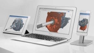
What is Cloud Based CAD? In a simplistic sense, it means that instead of having CAD software resident locally on CAD workstations or on local network servers, cloud-based solutions enable CAD software to be loaded and run remotely, and to be accessible on the internet to an approved CAD professional.

Before answering the question ”How Quickly is Cloud Based CAD being adopted?”, it is useful to know whether there are incentives for CAD organizations to be interested in cloud-based CAD.

  • Is cloud-based computing a novelty, or does it provide benefits such as cost savings, improved productivity, and protection of intellectual property?
  • Are there disadvantages or drawbacks which should be considered before using cloud-based CAD, instead of locally based CAD?

Cloud Based CAD

Answers to these two questions will make it easier to interpret and understand existing data regarding adoption rates for cloud-based CAD. Specifically:

  • Is cloud-based CAD growing, shrinking, or at a standstill?
  • If cloud-based CAD is growing, will it continue to grow? If it is not growing, why is that the case?
  • If cloud-based CAD will grow, at what projected rate?

What Benefits and Drawbacks Does Cloud-based CAD Provide?

Some of the benefits of using cloud-based CAD are:

  • Reduced capital expenditure, because it reduces the need to purchase and maintain workstations
  • Reduced cost of licensing CAD software on individual workstations
  • Global access to CAD software, and elimination of the need to co-locate CAD personnel
  • Increased productivity and collaboration
  • Provision for data backup and recovery, and certain levels of security
  • Reduced energy usage and reduced carbon emissions

Some of the drawbacks are:

  • The risk of security breaches and the danger of losing sensitive business data to hackers
  • Availability issues due to downtime or system outages
  • Inadequate internet bandwidth for certain mission-critical projects
  • Loss of control over company data, and the risk of entrusting protection of company data to an external organization
  • The potential for hacker intrusion and theft of sensitive, classified data

Is There Resistance To Adopting Cloud-based CAD?

The benefits of cloud based CAD seem compelling from a business viewpoint, even if there are some drawbacks. However, it appears from published reports that the current adoption rate of cloud-based CAD is probably between 20% and 30%. Although many businesses are seriously considering the adoption of cloud-based computing, either they have done so in a limited way, or they have not taken the plunge.

Since cloud-based computing provides many benefits, what reasons or concerns are delaying or resisting adoption of the service?

The three top concerns are:

  • Security (61%)
  • System Integration challenges (46%),
  • Information governance (35%).

This probably means that although many CAD organizations are carefully evaluating cloud-based offerings from many vendors, the organizations are in no hurry to adopt cloud-based CAD. This makes sense, because the potential for security breaches, the potential for hackers to steal sensitive company design data, and system performance issues are too risky to be taken lightly.

Until the drawbacks of cloud-based computing are resolved or eliminated, it makes sense for CAD organizations to:

  • Maintain software applications which handle sensitive company data on their own firewalled local servers,
  • Use cloud-based computing for handling data which does not require security clearance,
  • Use a combination of privately-maintained cloud computing together with locally-based computing (hybrid cloud computing).

It is necessary to define three main categories of cloud computing:

  1. Public cloud computing provides both computing resources and data management to the general public. The service is provided either freely or on a pay-per-usage model. This type of service is useful when security is not a major issue.
  2. Private cloud computing appeals to large enterprise organizations which have sensitive data, and require high levels of data protection and security clearance.
  3. Hybrid cloud computing uses the best of both public and private cloud computing. This is a good choice for CAD organizations which want to “test the water” before diving into fully-fledged cloud computing.

What Does Existing Data Say About Adoption Rates Of Cloud-based CAD?

The adoption rate for cloud-based computing depends on the type of software application. Although many types of cloud-based services are available, there are three main types:

  • SaaS (Software as a Service) or “on-demand” software migrates easily to the cloud, because security issues are minimal. Clients usually access SaaS with web browsers. The adoption rate is about 49%.
    Examples of SaaS are Google Apps, Microsoft Office 365, Twitter, Flickr, Dropbox, and Facebook.
  • PaaS (Platform as a Service) provides a computing platform on which software applications can be developed and deployed. Because PaaS provides a virtualized computing environment, software developers can focus on writing software without being concerned with attendant OS-driven tasks. The adoption rate is about 18%.
    Examples of PaaS are AWS (Amazon Web Services) Beanstalk, Google App Engine, Heroku, and Red Hat’s OpenShift.
  • IaaS (Infrastructure as a Service) provides scalable computing resources in a virtualized environment, and it manages cloud-enabled data.  Because IaaS clients have control over SaaS and PaaS clients, IaaS is the most likely candidate to be adopted by CAD organizations.
    IaaS could be used to develop applications for SaaS and PaaS environments. The adoption rate is about 28%.
    Examples of IaaS are Windows Azure, Rackspace, CloudSigma, HPCloud and Softlayer.

Is It Likely That The Adoption Rate Of Cloud-based CAD Will Grow?

A report by Cisco reveals that by 2018,

  • 31% of cloud workloads will use public cloud service,
  • 69% of cloud workloads will use private cloud service.

Furthermore,

  • 59% of cloud workloads will use SaaS, an increase of 41% from 2013,
  • 28% of cloud workloads will use IaaS, a decrease of 44% from 2013,
  • 13% of cloud workloads will use PaaS, a decrease of 15% from 2013.

If these projections hold true, the adoption rate of cloud-based CAD should either remain the same or decrease. Any more growth in the adoption of cloud-based CAD will probably occur as IaaS, within the realm of either private or hybrid cloud computing.

CAD Platforms in Product Designs

Importance of CAD Platforms in product designs

CAD Platforms in Product Designs

In the present age of rapidly computerized applications and CAD product designs, it is very likely that many future electromechanical products will have an embedded processor within them. Consider these two examples:

  • Several decades ago, the automobile industry designed automobiles with carburetion technology. This was been replaced by computer-driven electronic ignition systems. Likewise, manual braking was replaced by computer-assisted “antilock braking.” Recently, the concept of a computer-operated driverless car was mentioned as becoming a real possibility. The idea is not too far-fetched when you consider that computer-managed aeroplane navigation is a mature technology.
  • Many products such as copying machines, refrigerators, HVAC systems, and robotic systems provide real-time electronic communication between the customer and the manufacturer. For example, downtime for copying machines is significantly reduced because the product is proactive in sensing impending failures and calling for service. This makes the customer believe that the product is very reliable and virtually failure-free.

These two examples illustrate the trend in product development which combines CAD hardware design, embedded computer technology, and IT (Information Technology) into a package which changes a “dumb product” into a “smart product”. A smart product, therefore, communicates with both its manufacturer and with its customer in a manner which improves the functionality of the product and provides optimum performance of the product.

Best Importance of CAD Platforms in product designs Service

Computer-Aided Design (CAD) platforms play a crucial role in modern product design and development processes. Their importance stems from the numerous advantages they offer, which significantly enhance the efficiency, accuracy, and overall quality of the design process. Here are some key reasons why CAD platforms are essential in product design:

  1. Visualization and Conceptualization: CAD software allows designers to create detailed and realistic 3D models of products. This visualization capability helps designers and stakeholders better understand the concept and appearance of the final product before any physical prototypes are built. This leads to more informed design decisions and reduces the risk of costly design changes later in the process.
  2. Design Iteration and Flexibility: CAD platforms enable rapid prototyping and design iteration. Designers can easily modify and refine designs, test various configurations, and explore multiple ideas quickly and efficiently. This iterative approach leads to better designs and innovative solutions.
  3. Precise and Accurate Measurements: CAD software ensures high levels of accuracy in measurements and dimensions. This is crucial for ensuring that components fit together properly, align with industry standards, and function as intended. Accurate measurements also help in manufacturing and assembly processes.
  4. Collaboration and Communication: CAD platforms facilitate collaboration among cross-functional teams, including designers, engineers, manufacturers, and stakeholders. Designs can be easily shared and reviewed, leading to better communication and alignment among team members, even if they are geographically dispersed.
  5. Simulation and Analysis: Many CAD tools offer simulation and analysis features that allow designers to test how a product will perform under different conditions. This can include stress analysis, fluid dynamics, thermal simulations, and more. Identifying potential issues and optimizing designs early in the process reduces the likelihood of costly redesigns and failures later on.
  6. Reduced Time-to-Market: The use of CAD platforms accelerates the product development timeline. By streamlining design processes, minimizing errors, and enabling parallel workflows (such as design and analysis simultaneously), CAD tools contribute to faster product development and a reduced time-to-market.
  7. Cost Savings: CAD platforms help identify design flaws, interferences, and other issues early in the design phase. By catching these problems before physical prototypes are built or production begins, companies can avoid costly rework, material waste, and potential recalls.
  8. Customization and Personalization: CAD tools facilitate the creation of customized and personalized products. Designers can easily modify designs to meet individual customer needs, leading to more customer satisfaction and market competitiveness.
  9. Documentation and Manufacturing Support: CAD software generates detailed design documentation, including engineering drawings, specifications, and assembly instructions. This documentation is essential for communicating design intent to manufacturers and suppliers, ensuring consistent production quality.
  10. Long-Term Maintenance and Updates: CAD files serve as a digital record of the product's design and can be used for future modifications, updates, or maintenance. This is particularly valuable for products with long lifecycles or those that require periodic design improvements.

In summary, CAD platforms are indispensable tools that enhance the entire product design and development process, from initial concept to final production. They contribute to improved design quality, faster development cycles, reduced costs, and better collaboration across multidisciplinary teams.


Australian Design and drafting Services

How to reduce design and drafting cost?

Do you know, how much it cost to design a home? Here, the answer is quite simple. All you require to do is to outsource ASTCAD Design & Drafting. It helps to avail of cutting-edge 2D design drafting solutions for Australia, without investing in expensive technology or going through tedious recruitment headaches. Below, we have listed the importance of effective 2D drafting and the varied types of 2D drafting services that offer numerous benefits that come with outsourcing to ASTCAD Design & Drafting.

If your firm drawing is designed for a home, office, restaurant, or other type of building, you should be aware of its critical role. The 2D drafting offers a successful outcome of a building. 2D drafting is one step ahead that cannot afford to skip, even though you may encounter other problems while designing. Furthermore, 2D drafting provides time, skill and expertise. Using outsourcing, you need not to worry about 2D drafting anymore. You have to outsource 2D drafting to Australian Design & Drafting along with enjoying big savings on cost, time and effort.

How to reduce design and drafting cost?

No matter what type of design plan you’re looking for, you can avail an effective 2D drafting plan. Outsource to ASTCAD Design & Drafting using best mechanical engineers and 2D drafters. Put your skills and knowledge with delivering a cutting-edge 2D draft for your building. Avail 2D drafting services for the following:

  • Architectural drawings
  • Preliminary drawings
  • Millwork drawings
  • Assembly drawings
  • Shop drawings
  • Structural design drawings
  • Engineering (MEP) drawings
  • Presentation drawings
  • Machine drawings
  • Manufacturing drawings
  • Fabrication drawings
  • Structural steel detailing
  • Construction or working drawings

Here’s Why ASTCAD Design & Drafting Is the Preferred Outsourcing For 2D Design Drafting:

  1. Choose the latest 2D drafting software and tools that offer ASTCAD Design & Drafting by employing the latest 2D drafting tools such as, AutoCAD®, MicroStation®, SolidWorks®, Staad Pro®, Ansys®, 3DS Max®, VRay, X-Steel, Revit®, ProE®, Autodesk® Inventor®, CATIA®, and Unigraphics/NX to create world-class 2D drafts.
  1. Skilled 2D drafters: Outsource 2D drafting to ASTCAD Design & Drafting. It gives an access to a dedicated engineers and drafters team by collaborating with your company. We understand your needs and provide satisfactory 2D drafting solution. Our excellent team uses a 2D drafting solution used as preliminary drawing. Therefore, it includes architectural drawing, structural drawing, that develop a firm base for your design plans.
  1. 2D drafting in CAD: ASTCAD Design& Drafting provides an extensive knowledge of 2D drafting in CAD. It is based on exact scaling and specifications that one need to get.
  1. Huge cost savings: Simply cutting down on current cost by 50% while getting access to professionally drawn 2D drafts to meet your expectations.

Outsource to ASTCAD Design & Drafting, and work with the best people in the industry. It uses 2D drafting out of your hands and focus on your design plans. We offer dedicated team of skilled mechanical engineers that use ASTCAD Design & Drafting. It works out a 2D draft for your building ahead of your deadline.

Outsource 2D drafting to ASTCAD Design & Drafting with experiencing freedom from mundane recruitment, payroll or infrastructure-related hassles.

Which 2D drafting service would you prefer if you're looking to outsource? Have you outsourced 2D drafting before? If yes, how did it went? If you have a question outsource or express your views. Leave your comment in the box below. We, at ASTCAD Design & Drafting, love to hear from you.

How to CAD Modeling helping Water Distribution Systems

By using 3D modelling over the past 20 years, we have improved our engineer's ability to design, model, and fabricate complex parts for various industries. It covers automotive, aerospace, and biomedical. Let's say a tool that helps civil engineers, city planners, and construction crew to plan out networks for water distribution and wastewater management operations using a single mouse click. Such tools are readily available today and assist us in complex optimizations.

CAD Modeling helping

If we talk about network engineering, then they are a design of pressurized pipelines that is highly complex and require significant planning and understanding. It helps in regulations and design criteria. It is a highly time-consuming task that requires significant effort and prior knowledge with time.

Even with prior understanding, it offers cumbersome to meet the necessary design criteria. It includes a minimum pipeline slope, spacing between valves, and intersection with existing utilities. Along with adding other applicable quality standards to it.

DESIGN AND OPTIMISATION TOOLS FOR BETTER WATER INFRASTRUCTURE

Consider that your design comes with a water network along with a bottom-up approach. It uses the available water source and adds information on the constituent and tank-mixing in the design. Also, in such a scenario, the common questions might be:

  • How would the water system handle a fire?
  • What is the limitation of design in your water network?
  • Will there be enough water at each fire hydrant?
  • What happens if there comes excess flow from a particular location?
  • Will there be a sufficient flow of water that handles your system requirements?

CAD Modeling helping

The CAD programs use 3D modelling designed with complex water distribution systems. It provides the answer to the above questions. Bentley System's Water GEMS runs a stand-alone tool with MicroStation or AutoCAD tools. The Pipe Plan and Innovyze'sInfoWate tools offer a similar solution to it. The above tools are adopted by utility companies, municipalities, townships, and design engineers. They provide efficient design and optimization tools for water infrastructure and networks.

What are the advantages of using CAD to develop water distribution networks?

  • It comes with the ability to visualise the network in a 3D environment.
  • It offers the ability to model pipe pressures.
  • It helps in GPS tagging of the pipe network and existing pipes.
  • It allows designers to determine points of interference and avoid critical problem areas.
  • It has the ability to model-flow rate, loss nodes and pressures.
  • It is mainly used to design for high-flow conditions at a fire, which requires fire hydrants.

CAD REAL-TIME EXAMPLES AND ITS USE IN WATER DISTRIBUTION NETWORKS

The CAD tools are most likely to be used in civil engineering planning and design. Salt Lake City is used in Utah, and Huntington Beach in California are the two cities that have adopted WaterGEMS software for designing, optimising, and maintaining their water distribution networks. Salt Lake City's water distribution network helps to serve almost half a million residents, including over 1,000 miles of pipes.

It uses a complete geographical information system (GIS) for its water, sewer, and stormwater infrastructure. It is built into a model. It primarily uses WaterGEMS, a city currently building a hydraulic model for the water distribution system. It primarily uses existing data to update and maintain the city's expansion.

The tool mainly determines the optimal pipes that replace pipes. Some customers complained that the flow was insufficient during peak periods. They use guidance where the city can remediate the complaints. Further, they meet the fire department's flow requirement with 1500 gallons per minute for all fire hydrants along with high pressure.


CAD Modeling helping

BEST KNOWN CAD TOOLS FOR OPTIMISATION AND PIPING PLANS

WaterGEMS:

WaterGEMS is a tool used primarily to design, analyse, and optimise water distribution systems. Several features are used, such as WaterGEMS, covering steady-state and extended-period simulations. Along with constituent-concentration Analysis, source tracing, tank-mixing, water-age, and fire-flow analyses.

Additionally, there are controls used to rule-based logic and pumps for single or variable speed. The tools help users find operational bottlenecks by minimising energy consumption and modelling real-time operations. The critical Analysis is another essential feature that allows users to find the weak links and valves in the water distribution system.

The tool provides the ability to import CAD, GIS, database data and perform the polyline-to-pipe conversion from DXF files. The program includes optimisation tools that facilitate and enhance design iterations. It is more impressive that the program can directly link to Supervisory, Control, and Data Acquisition (SCADA) systems. It was named as SCADAConnect. Here the software tool provides an environment to monitor and control the network in real-time. They use the tool along with the pipe network model monitored in real-time. It allows a comparison of the model with the operation. The problem deficiencies investigate and evaluated using forensic performance analysis.

PipePlan: 

A second tool comes with a similar utility called Innovyze's PipePlan software. It provides a geospatial environment for water network analysis. It was designed for a detailed hydraulic network model. The design engineers produce and validate distribution and transmission line designs iteratively with minimal effort.

PipePlan allows horizontal and vertical alignments that help to define the location of pipe fittings such as bends, air valves, washouts, end caps and tees. It comes with an essential feature of the tool and its interference checking. It comes with automating report intersection with existing/proposed utility networks.

CONCLUSIONS

The tool maintains water distribution networks and goes through the challenging task for governments across the globe. In this context, the CAD software plays a significant role in enabling the proper water flow regulation. Also, it covers cities and urban areas that would continue to expand. Therefore, the tools like WaterGems and PipePlan comes with an even more critical role in providing efficient design and optimized water networks in the future.

Cad Importance in Product Development

CAD importance in Product Development

CAD and CAM are industrial computer applications, which have greatly reduced the time and cost cycles between initial concepts and product development. They have enabled designers and manufacturers to make significant cost savings. These tools also reduce the time to market for new products, and reduce the number of design flaws, which tend to hamper productivity, and in some cases ground an entire production cycle. Since the 1980s, CAD and CAM have provided exponential gains to both the quantity and quality of products.[/fusion_text][fusion_text]The primary advantages of CAD include the ability to:

  • reduce design cycle times
  • design a complex machine without the need to prototype
  • prototype parts directly from a CAD model
  • reduce low-cost design iterations rapidly
  • alter the designs quickly by changing geometrical parameters
  • view designs or parts under a variety of representations
  • virtually simulate real-world applications

CAM is the use of CAD data to control automated machinery for producing parts designed using CAD. The benefits of linking part fabrication directly to the CAD model include:

  • Direct control of computer numerical control (CNC) or direct numerical control (DNC) systems to produce exact replicas of the designs
  • Ability to skip the engineering drawing phase
  • Reduced part variability

How Boeing Set the Standard for Design Automation? - Cad Importance in Product Development -

Boeing is the world’s second-largest defence contractor and a leading manufacturer of aircraft, rockets, and satellites. CAD has played a major role in their product development planning and operations over the past three decades. Boeing announced the development of the 777 in the late 1980s, leading many aviation experts to question their decision. The design of an entirely new aircraft is a highly expensive task, whereas the success of the 747 models had been serving customers for over 30 years led experts to believe that the proper solution was to modify the 747 to suit passenger needs. Boeing applied a new approach that included customer inputs in the design phase from several major airlines, including United Airlines, Nippon Airways, British Airways, Japan Airlines and Cathay Pacific.

More importantly, Boeing invested over $1 billion in design automation using CAD based on CATIA (Computer Aided Three-dimensional Interactive Application) and ELFINI (Finite Element Analysis System) to design the new airliner that would turn out to become an industry standard. Both of these software packages were developed by Dassault Systemes of France. Boeing applied the following objectives to guide their break-through process:

  • Reduce aircraft development time significantly
  • Meet customer requirements better by involving them in the development process
  • Eliminate costly modification procedures

As a result, the 777 was the first aircraft in the world to be designed entirely using CAD technology. It was designed to maximize efficiency and quality. The completed design included over 3 million parts! The design process, its innovative features, and Boeing’s approach to manufacturing became the “Gold Standard” for development of future aircraft and were applied to a number of other projects, such as the International Space Station. The design was executed so successfully that a full-scale mock-up of the 777 was never built and was not necessary, reducing the design and production time. In fact, its first flight was so successful that the design was considered one of the most seamless and smoothest to date.

By using CAD models, design engineers were able to provide “built-in” options, which did not need to go to production, such as folding wing-tips. By developing options in CAD, the cost associated with such a trade study and its design is minimized.

What Benefits did Boeing Realize by Automating its Design Process? - Cad Importance in Product Development -

To assess the value of the design automation that Boeing implemented in their process by using 3D CAD modelling to design the 777, Boeing compared the effort with their previous design efforts (757 and 767). Overall, they realized:

  • 91% reduction in development time
  • 71% reduction in labour costs
  • Over 3000 assembly interfaces were developed virtually without the need for prototypes
  • Reduction in design and production flaws, mismatches, and associated errors
  • 90% reduction in engineering change requests from approximately 6000 to 600
  • 50% reduction in cycle time for engineering change request
  • 90% reduction in material rework
  • 50 times improvement in assembly tolerances for the fuselage.

It is notable that the design was completed at a time when CAD was not linked directly with FEA and CFD modelling software, but the effort has still been widely accepted as one of the greatest uses of CAD of its time.

The value of CAD modelling is just as valuable on a smaller scale, such as in the bicycle industry. For example, Cannondale is another pioneer that has utilized CAD and CAM technology since the 1990s to reduce its production cycle and reduce manufacturing costs, resulting in significantly higher production rates. As part of their integrated system design approach, Cannondale extended its production capability to produce custom designs for customers that are fit to their individual needs, resulting in over 7000 custom-fit designs that can be produced using their vertical integration production strategy. Their highly advanced model allows the company to maintain a competitive advantage in all aspects of design, performance, and production.

What Lessons can be Learnt from these Pioneers?

  • Leverage customer input early in the design process
  • Use CAD, CAM, and rapid prototyping of models to obtain valuable feedback from all stakeholders, including end customers, manufacturers, and suppliers
  • Reduce design times by applying CAD early in the design process no matter how small, simple, or complex your design.


Australian Design and drafting Services

Raster to Vector Conversion

Why you need your raster images to move towards vector images? Read on to find out more about Australian raster to vector conversion.

If you’re looking for a professional and diligent team of experts, we bring the best manual raster to vector conversion. You get the constant need for complex yet accurate drawings from the manufacturing or mechanical engineering industry. We have the best team that offer unique conversion requirements. Raster images show resolution-dependent and do not yield very accurate results. If you still use raster images, it’s time to move towards vector images, as it can generate accurate drawings and images.

Raster to Vector Conversion

With raster to vector conversion, one can effortlessly convert un-editable paper drawings into accurate vector files in the CAD software of your required choice. Later, the converted files can be saved in any vector format (WMF, EMF, AI, or EPS DXF). Once you convert your file into a vector, it can be effortlessly read by any CAD program like AutoCAD, Adobe Illustrator, Corel Draw, Microstation, VectorWorks, FastCAD or TrueCAD. Also, the raster to vector conversion is a direct replacement for traditional tracing and digitizing, which could be less accurate and more time-consuming.

Why use vector images in CAD programs?

We offer top-quality services to retain clients. The CAD programs help to import and display raster files, while you only can look at the file or trace it. Later, you will be unable to change it. It happens when CAD programs only work with vector files. If you want to change a raster file in your CAD program, you need to convert it into a vector file for raster to vector conversion. Once the file converts into a vector file, you can import it into a CAD program and edit it with ease.

How is a file converted from raster to vector?

  • Initially, a paper drawing is scanned using a scanner and created a raster file.
  • The file from raster to vector passes through raster to vector for conversion.
  • Later, the vector file imports into the CAD program.
  • Users can easily edit vector drawing in the CAD program.

Who requires raster to vector conversion?

  • CAD professionals who require a quick scan, convert and edit drawings using popular CAD programs.
  • Mechanical, electrical and architectural engineers do drawings done by hand and edited in CAD software.
  • Professionals convert small faxed drawings into vector drawings.
  • Technical professionals use several bitmap drawings and convert their data into an editable vector format.
  • Photo editing professionals convert photos/artwork into vector files for easy engraving or cutting.

Have you tried raster to vector conversion?

We know raster images consist of pixels and get lose when enlarged. Using raster to vector conversion services can quickly edit a drawing rather than redraw the entire concept from scratch. One can save countless hours on tracing, redrawing and digitizing. In short, vector graphics are defined as geometrical constructions. Why not choose raster to vector conversion for paper drawings right away? Get to know more about our low-cost, precise and super-fast raster to vector conversion services.

Drafting Services

Proof-of-Principle Prototypes

Proof-of-Principle (PoP) Prototypes are one cornerstone of engineering design. PoP, referred to as Proof-of-Concept, prototyping is an effective way to rapidly take ideas from intangible designs to tangible, working models. We have a professional team that offers flexibility and build the best PoP model.

Developing these prototypes enables the designer to demonstrate the fundamental technology used in the product that requires fabrication. It allows you to test your solution by ensuring that the functions are intended or envisioned. It creates fabricated prototypes from a CAD model that gives product developers a competitive edge by reducing design iteration times and associated costs.

Proof-of-Principle Prototypes

Our offered services from ASTCAD describes methods, advantages, and disadvantages of the essential rapid prototyping processes. It uses product design engineers to meet development milestones. By taking your design from a CAD model to a proof-of-principle prototype, we accelerate design and add new products to market more efficiently. We used the proper process and CAD models that quickly transformed into a working prototype. Get the best intellectual function model with a mechanically feasible solution.

POP PROTOTYPE ADVANTAGES

Advantages Of POP Prototyping Include:

  • Reduces product development time.
  • Makes design flaws apparent.
  • Reduces product development costs.
  • Results in higher quality end products.
  • Offers a demonstration tool for obtaining user feedback.
  • Makes potential future system enhancements clear to engineers and inventors.

POP PROTOTYPE DISADVANTAGES

Disadvantages Of PoP Prototyping Include:

  • It may not include all of the features of a more complex complete system.
  • It cannot be used in place of rigorous system analysis.
  • It may not be representative of the full functionality of the end product.
  • Can lead to over-confidence in the solution.

PROOF-OF-PRINCIPLE PROTOTYPING METHODS AND PROCESSES

We find several ways to design your prototype. It is referred to as Rapid Prototyping, where the methods offer an initial fabrication of your design. The processes create prototypes which include Additive Processes. It’s the part used to build built-in subsequent layers, where the material is removed to make the final product called Injection Moulding. The thermoplastics are injected into harmful moulds and cast using urethane thermoset resins.

  • The additive processes build using plastic parts are layer by layer directly from a 3D CAD model. The 3D printers are developed for most additive processes and gained tremendous acclaim.
  • The Stereolithography (SLA) lasers cure thin layers of liquid UV-sensitive photopolymer. The SLA is cost-effective and used to produce intricate parts. It offers the best look and feels with the finished product. However, it tends to make parts that are relatively weak and have little UV stability due to the UV curing process.
  • Fused Deposition Modelling (FDM) works similar to SLA. It uses layers of extruded thermoplastic to create the part. The method offers complex, structurally sound roles and can use for limited mechanical and functional testing. The surface finish is poor compared to other methods as defined.
  • Selective Laser Sintering (SLS) is one method that creates the best part adhering to layers of polymer powder that cured using a laser. SLS prototypes are made with more complexity than parts made with SLA. Additionally, the details tend to have a rough texture and poor mechanical properties.
  • Direct Metal Laser Sintering (DMLS) mainly uses laser-generated heat that sinter thin layers of metal powders, including steel, cobalt-chromium, stainless steel, and titanium, to generate prototypes. DMLS parts offer highly realistic details and are less cost-effective than their plastic counterparts. It often leads designers to produce cheaper plastic and use prototypes that have the product fully machined.
  • The Polyjet uses a process that utilizes jetting heads and UV curing bulbs, which apply consecutive material layers in multiple colours and durometer in a single build. The method offers a representation of multi-material parts with excellent surface finish quality. The mechanical properties use the Polyjet process with ease.
  • Subtractive processes come with raw material and machine away with excess volume to produce a final part.
  • CNC Machining (CNC) is also one the most common example. It uses CNC machining, a part that can be produced from almost any variety of materials that include both plastics and metal. The advantages of CNC machined parts are highly accurate, made with the mechanical properties of the final product, and come with a highly polished and professional finish. Limitations include fewer complex geometries due to the tooling nature and significantly higher costs.
  • Injection Moulding is a popular prototyping process that cures thermoplastics into a mould from soft metal. The process is highly cost-effective and uses only one method representing the volume production fabrication. A wide range of resins is used with different properties and allow the parts to match up with the properties of the final product. The final cost per unit is typically different and is inexpensive, even after factoring in the cost of the mould. Still, the initial non-recurring engineering cost of the mould requires a significant up-front investment.
  • Casting is similar to injection moulding and uses a master model that fabricates using another method like SLA to create a silicone rubber mould. Liquid urethane thermoset resin is then used to generate the prototype. The urethane can be made to match any colour or texture. It uses highly cost-effective parts and has limited use in functional testing.

Whatever your proof-of-principle prototype requires, a suitable rapid prototype is used with a CAD model and material/finish selection. It is essential to consider the method, time to fabricate, cost of the prototype part, and the manufacturer, as the quality of a part varies rapidly between one fabricator and the next.