1800 287 223 · [email protected]
CAD Design

If you think the idea of having driverless cars on the roads seems dangerous and utopian, think again — driverless car CAD design is already here, because the idea is quickly becoming reality. Actually, we have been using certain features of driverless cars for some time. Until recently, automobiles did not have cruise control, automatic and antilock braking, temperature sensors, GPS technology, or road sensing technology. That has all changed.[/fusion_text][fusion_text]The autopilot system for air travel has been available for a long time, and the maturity and reliability of the technology continue to improve. If automatic piloting of complex aircraft in busy airspaces is acceptable, why should driverless cars not be acceptable?

Driverless Car CAD Designs

A partial list of technologies required to create driverless cars are the following:

  • Onboard computer technology,
  • Onboard telemetry (radar and laser sensors),
  • Anti-lock and automatic braking systems,
  • Adaptive cruise control,
  • GPS and sensor technology,
  • Traction and stability control,
  • Automatic engine control,
  • Computerised navigational system.

This article focuses on CAD-related technologies which could be involved in building driverless cars. Specifically, the article discusses how the following technologies (which involve CAD design) will affect driverless cars:

  • The role of sensors, GPS technology, and video cameras for driverless cars,
  • Leading players in the development of driverless cars,
  • Benefits which driverless cars will provide,
  • Problems which driverless cars could create.

The role of sensors, GPS technology, and video cameras for driverless cars

The following technologies will help implement driverless car technology while providing collision avoidance and traffic safety:

  • Video cameras will detect traffic lights, read road signs, keep track of neighbouring vehicles, and look out for pedestrians, pets and other obstacles.
  • LIDAR (Laser Illuminating Detection and Ranging) sensors will detect edges of roads and identify lane markings by bouncing light pulses off the car’s surroundings.
  • Ultrasonic non-contact sensors in the wheels will detect the position of curbs and neighbouring vehicles during parking.
  • GPS technology will use the location of the vehicle to determine routing, speed limits and to provide navigational guidance.
  • Onboard telemetry will enable cars to communicate with one another, and with traffic monitoring and control systems.
  • The onboard computer will analyse all monitored and measured data in order to make navigational decisions regarding steering, acceleration or deceleration, and braking.

Leading players in the development of driverless cars

It is not within the scope of this article to list the names and accomplishments of all leading players in driverless car technology. It will suffice to highlight two significant accomplishments. Israel’s Mobileye® made news recently when its driverless vehicle supplied by Delphi Automotive traversed a 3,000-mile journey from San Francisco to Manhattan in 9 days. Before this accomplishment, the driverless vehicle had been successfully operated in Los Angeles and Las Vegas. The driverless vehicle could detect cyclists, debris on the road, curbs, barriers, construction zones, traffic lights, and road signs.
Mobileye expects to offer 237 driverless car models by the end of 2016.
Deals to use the technology have already been made with BMW, Chrysler, Ford, General Motors, Nissan, Peugeot, Volvo and Tesla. Truck manufacturers MAN SE, Scania, and IVECO have also made deals to use the technology.
In 2014, Google unveiled the technology named “Google Chauffeur” for piloting autonomous or driverless cars. Google’s technology neither uses a steering wheel nor a brake pedal.
Automotive companies which have signed on to use Google’s technology include Toyota Prius, Audi TT, and Lexus RX450h. Google’s robotic car uses a LIDAR system which generates a detailed local map of its environment. The generated map is combined with high-resolution maps of the world in order to produce data models that the computer uses to pilot the vehicle.
Google’s driverless vehicles have been tested in the San Francisco area, and they have logged about 700,000 miles (1.1 million km) of accident-free driving. Google plans to make its driverless cars publicly available by 2020.

Benefits which driverless cars will provide

In order to enjoy the benefits that driverless cars will provide, it is necessary for legislative bodies to pass or modify traffic laws. In the United States, the District of Columbia and four states have already passed laws that permit the operation of driverless cars. Many other state legislatures are discussing the passage of similar laws.

Predictably, the public will initially be sceptical about operating driverless cars, until the following benefits become evident.

  • There will be a significant reduction in vehicle collisions, injuries caused by automobile accidents, and loss of life. Consequently, the cost of insuring motor vehicles will be lower.
  • There will be less need for individual driving licenses and driving skills.
  • Senior citizens, teenagers, and handicapped people will have the mobility that they do not now have.
  • A businessman or woman could work or play (read the newspaper or a book, watch TV, eat or drink) instead of focusing on driving to work. The need for police officers to arrest motorists for DUI, which is a leading cause of traffic deaths, will be gone.
  • Law enforcement will have more manpower to fight crime instead of enforcing traffic laws.

Problems which driverless cars could create

It should not come as a surprise that whenever new technology is introduced to benefit mankind, criminal minds will find ways to misuse the technology for personal profit or to cause mischief. What problems could arise?

  • Criminals will hack into onboard computer systems in order to steal automobiles.
  • Terrorists will hack into traffic control systems and into car computer systems in order to create accidents, traffic jams, or chaos.

Law enforcement will need the training to fight these new types of traffic crime. The use of the internet, GPS, and drone technology could become useful instruments for enforcing traffic safety.

Conclusions

Driving as we know it is about to change in a dramatic way. Although many technical problems remain to be solved, the use of driverless vehicles should accelerate rapidly by the year 2020.

Initially, driverless cars will be expensive. When the costs of these vehicles come down, almost everyone (including senior citizens, children, drunk drivers, and even blind people) will have the privilege of using driverless cars without endangering the lives of the public or themselves.


JH

James Hartley

Senior Mechanical Engineer · BEng (Mechanical), UQ · Member, Engineers Australia · ASTCAD, Brisbane

James has 14 years of hands-on experience delivering CAD design, structural drafting, and engineering documentation across Australia’s mining, oil & gas, and manufacturing sectors. He specialises in SolidWorks, Autodesk Inventor, and AutoCAD for complex multi-discipline projects.

More articles by James Hartley →
CAD Design

CAD for wearables design is rewriting health history. The majority of people born before the 1900 year haven’t lived past 50 years of age. In the 20th century, life expectancy increased dramatically. Today, the life expectancy is over 80 years in several developed countries.

For over 85 years, people have been estimated to comprise about 8% of the total world population. Furthermore, the cost of health care continues to rise, and expect a large number of health care that could stress the health care systems of several nations.

Although it’s welcome news that increases life expectancy, living to a good old age. There won’t be any means without a good quality of life. Old, diseased or disabled poor senior citizens create burdens for home and caregivers. It increases the health care cost and insurance for the entire population.

The one way to maintain a good quality of life for the elderly is to find efficient and inexpensive methods to monitor their health. Doing so makes it take preventive measures to combat diseases and treat diseases and ailments before it becomes difficult and expensive to handle.

CAD for wearables design: a partial list of steps that have been taken to increase life expectancy:

  • It reduces the transmission of infectious and parasitic diseases.
  • They immunize against polio, smallpox, measles, and major childhood diseases.
  • Supports improving living conditions by offering clean water and nutritious diets.
  • It offers health awareness and education to minimise exposure and other health risks. It includes toxic substances, alcohol, smoking, poor diet, with lack of exercise.
  • It includes funding the developmentof advanced drugs to fight and treat diseases.
  • It provides health monitoring, injury control and health management.

The last item, “offer health monitoring, health management and injury control”, uses modern CAD-related technology that forms wearable medical devices and focuses on this article.

In the article, we’ll get answer these questions:

  • What are wearable medical devices?
  • In what ways are wearable used in medical devices CAD-related?
  • Which wearable medical devices are commonly used?
  • What trends are likely to use wearable medical devices? 

What are Wearable Medical Devices CAD Design?

Wearable medical devices are biosensors attached to the body to monitor physiological data. It usually uses remote or wireless communication. As these devices are wearable, they provide 24/7 medical data to physicians that help to deliver easy health care.

Examples:

  • A small shirt worn by athletes to measure heart rate offers vital physiological data that is analysed and used for training.
  • A pulse oximeter is mainly worn on a finger to measure pulse rate and blood oxygen saturation reliably.
  • Wearable blood pressure monitors the arm’s worn to measure blood pressure and heart rate.

In what ways are wearable medical devices CAD design-related?

One essential role that CAD technology plays in creating wearable medical devices includes Additive Manufacturing or 3D printing wearable items. Let’s say a Swedish company, Decomed Design, works with CAD engineers, designers, IT professionals, and physicians to create stylish 3D printed wearable medical devices called an Akufeel bracelet.

The bracelet comes with an anti-nausea device worn on the wrist. The device offers pressure to an acupressure point from the inside of the wrist to relieve nausea symptoms. It could arise due to pregnancy, motion sickness, the flu, side effects of medication, etc.

With the stylish nature of the bracelet, the wearer could be happy to add adornment to their attire while enjoying an improved life quality.

Additive Manufacturing mainly creates wearable medical devices in shoes, vests, hearing aids, implants, prosthetics, and more. 

Which wearable medical devices are in most commonly used?

The majority of easy to design wearable medical devices could measure activity and exercise. It includes calorie-burn rate, heart rate, blood pressure, or distance walked. Also, wearable computers, smartwatches, and smart clothing provide measurements. One needs to have an interest in building sophisticated wearable medical devices. These devices help monitor complicated physiological functions such as brain activity, EKG, glucose levels, hydration, oxygen level, temperature, sleep, and several other vital functions. The scope of this article provides an exhaustive list of wearable medical devices. It’s worthwhile to name a few of them.

Zephyr® manufactures a bio-data logger called Zephyr BioHarness, which monitors posture, activity, breathing, and ECG. It can transmit data within a 10-meter range, which is helpful for Remote Patient Monitoring. The Medtronic® manufactures cover FDA approved CGM (Continuous Glucose Monitor) and a diabetes management system that includes an insulin pump. Additionally, Omron® manufactures an FDA-approved pain relief device for the lower back, arm, leg, or foot. 

What trends are likely for the use of wearable medical devices?

A breakthrough wearable device offer emerges controlling diabetes. It helps in research work performed at UC San Diego’s Center for Wearable Sensors. The researchers develop wearable medical devices that work by measuring chemical markers. It includes potassium or lactic acid levels present in sweat or saliva.

The wearable blood glucose level monitors the devices that extract interstitial fluid below the skin to the surface. There’s no penetration of the skin to measure blood glucose levels.

Expect regulatory bodies, including FDA and establish well-defined guidelines on the manufacture. It uses wearable medical devices. Wearable medical devices come with a failure mode caused by chemical reactions between the device and the skin, poor wireless communication, battery safety, or electric shocks.

Failure mechanisms become well understood. It covers reliable and wearable medical devices. It is manufactured with predictable and dependable lifetimes. Its data transmission protocols and device reliability become robust, patient care with depending heavily on the use of wearable medical devices. Thus, healthcare costs reduce fewer patients confined to hospital beds.


JH

James Hartley

Senior Mechanical Engineer · BEng (Mechanical), UQ · Member, Engineers Australia · ASTCAD, Brisbane

James has 14 years of hands-on experience delivering CAD design, structural drafting, and engineering documentation across Australia’s mining, oil & gas, and manufacturing sectors. He specialises in SolidWorks, Autodesk Inventor, and AutoCAD for complex multi-discipline projects.

More articles by James Hartley →
CAD Innovations in Rapid Prototyping

Rapid Prototyping showcases how CAD innovations offer advanced ability to design and fabricate models. Along with using proof-of-principle prototypes. Whereas in some cases, it uses functional components. Also, it adds well-established Additive Processes, whereby plastic parts are mostly built layer by layer directly from a 3D CAD model. Some of the standard techniques include:

Stereo Lithography (SLA)

Selective Laser Sintering (SLS)

Direct Metal Laser Sintering (DMLS)

Fused Deposition Modelling (FDM)

The Polyjet Process

Computer Numeric Control (CNC) machinery mainly uses a well-known subtractive process and uses machines, billets and other desired parts. Whereas on the other hand, it uses rapid prototyping processes that cover Injection Moulding and Casting. It uses master moulds that inject cast plastic or any other urethane parts.

Several methods, techniques, and approaches are used that add rapid prototyping parts. It includes components that are developed each year. Some of the most exciting developments are shown below:

(CAD Innovations in Rapid Prototyping) FORD’S F3T RAPID STAMPING PROCESS

Ford Motor Company mainly uses sheet metal parts that assemble vehicles and develop world-renowned sheet metal fabrication. The process that takes a new design from a CAD model to a prototype can be time-consuming.

The latency increases the design iteration time, makes it highly cumbersome and excellent off prototypes and test-fit new designs. Recently, ford created a new rapid process, which they call the Ford Freeform Fabrication Technology (F3T). It’s a part of a three-year, $7.04 M, U.S. The department of Energy-funded effort mainly uses next-generation manufacturing and energy-efficient processes. The new short-run stamping technology offers low costs with fewer delivery times for low-quantity run sheet metal parts.

The process mostly begins with a CAD model, which creates a Computer Numeric Control (CNC) tool path and works similar to the path. It is used by a 3D printer with generating the part. It directs position with keeping in-depth dual-arm robot. It holds tools in both arms as the process sheets into shape. Additionally, it allows prototypes and small production that run cost-effectively with shorter lead times. The customisation comes with viable design cost iterations, and it offers drastically reduced change. The short-run stamping process is used with bigger applications in various industries.

(CAD Innovations in Rapid Prototyping) LARGE-SCALE 3D PRINTERS

It’s a kind of exciting area of innovation used in rapid prototyping. It uses 3D printers for building models and working prototypes which were impossible until now. The 3D printers are capable of printing vehicles and provide tiny houses. The researchers at the Oak Ridge National Laboratory and Cincinnati Incorporated developed a printer capable of using Additive Processes by building the Stratis Car. The machine, named Big Area Additive Manufacturing (BAAM), makes a volume of 7′ x 13′ x 3′ along with a deposition rate of 40 lbs/hr against BAAM’s rate of 40 lbs/hr. The system supports to combines 3D printing along with CNC routing with the largest high-quality 3D printing. Also, the second generation of this technology, referred to as Bertha, feature a volume of 8′ x 20′ x 6′ and a 100 lbs/hr deposition rate.

The other researchers develop technologies that revolutionize the housing industry by using Additive Manufacturing and building structures. Massimo Moretti devoted his time by applying 3D printer technologies and providing rapid prototype solutions. It caters to the housing crisis in developing countries across the world.

Additionally, the project is known for the World’s Advanced Saving Project (WASP). It mimics the construction method of the Mud Dauber Wasp building its nest. The primary goal of the technology is to build houses that add no cost by using materials. They are readily available on-site in third-world countries.

The complete system is designed with two people that assemble a 3D printer within 2 hours. The researchers at Winsun New Materials allow China to spend USD 3.2M over 12 years by developing an enormous 3D printer.

The printer measures a whopping 6.6m tall, 10m wide and 150m long. The houses print layer by layer using a mixture of cement and glass fibres. It helps to create a solid composite structure. Recently, Winsun proved that it built ten houses of 200 square meters in size using recycled construction and industrial waste in less than a few hours at the cost of only $4,800 each. 

3D printed jet engines

The scope of 3D printing has been confined to housing. It has extended to jet engines, which are extremely difficult to build, including many intricate parts machined from many features with high tolerances for a seamless assembly.

The researchers at the Monash Centre comes with an Additive Manufacturing. Australia has produced the first 3D printed jet engine. It is based on an auxiliary powered gas turbine engine from Safran, a French aerospace firm. The Monash Centre mainly uses Concept Laser’s X line 1000R 3D printer. A state-of-the-art industrial printer fabricates components from metal powder by using sizes up to 60cm x 40cm x 50cm.

Whatever your proof-of-principle prototype requires. It is a suitable rapid prototype method that exists by adding CAD model and material/finish selection that the Software delivers. STP files enable customers by bringing ideas to life. We at Australian Design and Drafting help individuals and companies alike in this endeavour. The possibilities come endless as the technology becomes more viable and extends large sheet metals.


JH

James Hartley

Senior Mechanical Engineer · BEng (Mechanical), UQ · Member, Engineers Australia · ASTCAD, Brisbane

James has 14 years of hands-on experience delivering CAD design, structural drafting, and engineering documentation across Australia’s mining, oil & gas, and manufacturing sectors. He specialises in SolidWorks, Autodesk Inventor, and AutoCAD for complex multi-discipline projects.

More articles by James Hartley →

Related reading: proof-of-principle prototypes.

3D print

3D print for using beer – Design and Drafting Service

The idea of a 3D print beer filament sounds odd. When talking about 3D print, they are not just the machines progressing and evolving, but it comes with the materials used to print the products. One of the best US companies named 3Dom is specialises in offering eco-friendly printing filaments.

It came up with a way to 3D print and use a material made from beer waste. They named it Buzzed. It consists of the leftover hops and barley. They have added filament to it, which is a visible grain, so the colour you get can print inconsistently. It includes the quirkiness of the material along with it.

3D print for best using beer 

3Dom said, “One does not require any particular 3D printer to use Buzzed, instead use a machine that is capable of printing Polylactic acid (PLA)”. One can try a 3D printer that’s available on the market. Buzzed mostly uses beer leftovers to create exceptional 3D printing materials. They use the filament in a unique way with giving a finished print. Additionally, the filament helps produce rich golden colour products and provide a noticeable natural grain.

Beer aficionados and enthusiasts alike are constantly seeking new ways to elevate their drinking experience. Enter 3D printing, a technology that’s revolutionizing industries across the board, including the world of beer. From customised accessories to innovative brewing tools, 3D printing opens up a realm of possibilities for beer lovers. Let’s explore how this cutting-edge technology can enhance your enjoyment of the beloved brew.

  1. Personalized Beer Accessories: Imagine sipping your favourite craft beer from a personalized, 3D-printed beer mug or stein, perfectly tailored to your grip and style. With 3D printing, you can design and create unique drinking vessels that reflect your personality and enhance your enjoyment of every sip. From intricate designs to ergonomic handles, the options are limitless, allowing you to elevate your beer-drinking experience like never before.
  2. Custom Tap Handles: For homebrewers and beer enthusiasts who take pride in their craft, custom tap handles are a must-have accessory. With 3D printing, you can design and produce tap handles that showcase your brand or favourite brew in stunning detail. Whether you prefer a classic design or something more whimsical, 3D printing enables you to bring your vision to life and add a touch of flair to your home bar or kegerator setup.
  3. Innovative Brewing Tools: Beyond just accessories, 3D printing offers practical solutions for enhancing the brewing process itself. From fermenter accessories to kegging equipment, 3D-printed components can streamline operations and improve the quality of your homemade brews. Need a custom hop infuser or a specialised bottle capper? With 3D printing, you can prototype and produce these tools with ease, allowing you to experiment and innovate in your brewing endeavours.
  4. Beer-inspired Art and Decor: For beer enthusiasts who appreciate the aesthetic side of brewing, 3D printing offers endless opportunities for creating beer-inspired art and decor. From sculptures and wall art to intricate beer-themed trinkets, 3D printing allows you to bring your favourite brews to life in stunning detail. Whether you’re decorating your home bar or looking for unique gifts for fellow beer lovers, 3D-printed creations add a touch of craftsmanship and creativity to any space.

JH

James Hartley

Senior Mechanical Engineer · BEng (Mechanical), UQ · Member, Engineers Australia · ASTCAD, Brisbane

James has 14 years of hands-on experience delivering CAD design, structural drafting, and engineering documentation across Australia’s mining, oil & gas, and manufacturing sectors. He specialises in SolidWorks, Autodesk Inventor, and AutoCAD for complex multi-discipline projects.

More articles by James Hartley →
3D Printing

3D printing technology uses the latest “ultra-cool” movement. 3D printing houses went from fantasy to reality fast. Ever since we heard about 3D printing, we remember the small 3D printers. It began to imagine how the world would look if 3D printing became such a common procedure as paper printing.

There’s a world full of home-made toys, dishes, utensils, and lots more. What if 3D printing offer excellent solution with solve the issue of shelter around the globe. What if there could provide a feasible solution to a 3D print houses?

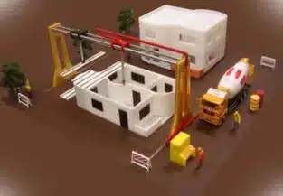
The idea of ContourCrafting comes when CEO offer a very insightful TED talk. The Professor Behrokh Khoshnevis, from the University of Southern California, is the man that have built this awesome concept. In simple words, he wants to make a 3D printer within 20 hours. The vast 3D home builder creates the entire building, from the foundation, floor, ceiling, and plumbing. At the beginning, we thought it could build the main block of the building.

The 3D printer from ContourCrafting is far more crafted than this. It would build houses in such a way that you’d only require to put the windows and the doors in the cutouts. The vast construction robot left this. Maybe one wouldn’t like living in such a home built by a gigantic 3D printer.

But almost 1 billion people don’t have stable shelter. Therefore, do you think, they’ll think twice before moving in? It can be an immediate and most urgent use for 3D printed home. But I can imagine that the rest of us, or those with money, can print their own house in less than one day.

Inspiring 3D printing houses that will reshape the construction

Right from the start, we were confused that how to build big buildings with hundreds of flats? How are they going to achieve that? But the CountourCrafting guys created the model of a 3D printer. It’s building that capable of designing everything. And something that surprised was some 3D printer capable of climbing and finishing the printing to a next level.

The technology seems very impressive and can build more advanced buildings using advanced designs. We use a perfectly calculated geometry using the strong material. The house-building with 3D printers can replicate historic or progressive buildings. How cool, isn’t it.

It does sounds excellent on paper, but what’s the reality…

Behrokh Khosnevis says, this technology is far more secure and safe than current construction methods. He said that the 10,000 workers die each year in the USA and 400,000 get injured during construction. But with 3D construction printers, we could eliminate and decrease lot of the time that require to build a house. There are drawbacks that we can’t ignore. Let’s discuss them.

3D printing house to build in 20 hours!

Imagine how many jobs get lost if the technology were become mainstreams. We have a team that supports a civilization and rely on the technology. Thus, with being more automated, it manually runs using this technology. Few houses are built using this concept, but it will not gain mass appeal as the government requires to keep the population employed. But again, the same thing happened when the Industrial Revolution began.

The people were afraid that they would lose jobs as technological devices were there to take tasks from humans. But when we look behind, we see that humanity has found a place for everybody. It can be an issue for the moment, but imagine that by 2050 or beyond 3D printed homes not be just a “cool concept”. Instead, it could be something ordinary. The appearance of the Web won’t kill jobs, it could change the world. The 3D printing won’t kill construction, it can reshape in near future.

What a brave new world it could be?

The technology is excited that it wants to be a part of it. One can see 3D printed houses around and people living in them. One can see huge 3D printers outside the towns. There could be building from the ground homes for everybody. Let’s imagine using this technology, one can build houses on other planets as well. Get connected, if you’re looking for a leading Australian design and drafting service company, here we are to help you solve your problem.

Is 3D printed house strong?

The strength of a 3D-printed house depends on various factors such as the materials used, the printing technology, the design, and the structural integrity. Generally, 3D-printed houses can be quite strong and durable if they are designed and constructed properly. Many construction companies are exploring the use of high-strength materials like concrete, composite materials, and even advanced polymers for 3D printing homes. Additionally, the ability to create intricate geometries and customized designs through 3D printing can sometimes result in structures that are more robust than traditional construction methods. However, it’s essential to ensure that the printing process is carefully controlled and monitored to maintain quality and structural integrity. Overall, with the right materials and techniques, 3D-printed houses can indeed be strong and reliable.

What are the disadvantages of 3D printed houses?

While 3D printed houses offer numerous advantages, they also come with some disadvantages:
Limited Materials: Currently, most 3D printed houses are constructed using materials like concrete or synthetic materials, which may not be as environmentally friendly as traditional building materials like wood or brick.
Limited Design Flexibility: While 3D printing allows for innovative designs, it can also limit the architectural freedom compared to traditional construction methods. Intricate designs or non-standard shapes may be challenging to achieve.
Quality Control Challenges: Ensuring the structural integrity and quality of a 3D printed house can be challenging, especially if the printing process encounters errors or inconsistencies. Quality control measures need to be robust to guarantee the safety and longevity of the structure.
Dependency on Technology: 3D printing technology is still evolving, and reliance on it for construction means being dependent on the advancements and reliability of this technology. Technical glitches or failures in the printing process can lead to delays and added costs.
Regulatory Hurdles: Building codes and regulations often lag behind technological advancements. Incorporating 3D printed houses into existing regulatory frameworks may require significant adaptation and approval processes, which can be time-consuming and cumbersome.
Scalability Challenges: While 3D printing has the potential to revolutionize construction, scaling up the technology for mass adoption on a large scale presents logistical and infrastructure challenges. The current scale of 3D printing is limited, and widespread adoption would require significant investment and infrastructure development.
Skilled Labor Requirement: Despite automation in the printing process, skilled labor is still required for setup, maintenance, and finishing work. Ensuring an adequate workforce with the necessary skills to operate and maintain 3D printing equipment can be a challenge.
Perception and Trust: Acceptance of 3D printed houses among consumers, builders, and regulators may be hindered by skepticism or distrust regarding the durability, safety, and longevity of these structures. Building confidence in the technology and its capabilities is crucial for widespread adoption.
Cost Considerations: While 3D printing has the potential to reduce construction costs in the long run, initial setup costs, including investment in printing equipment and infrastructure, may be substantial. Additionally, the cost-effectiveness of 3D printing may vary depending on factors such as project size, location, and material availability.


JH

James Hartley

Senior Mechanical Engineer · BEng (Mechanical), UQ · Member, Engineers Australia · ASTCAD, Brisbane

James has 14 years of hands-on experience delivering CAD design, structural drafting, and engineering documentation across Australia’s mining, oil & gas, and manufacturing sectors. He specialises in SolidWorks, Autodesk Inventor, and AutoCAD for complex multi-discipline projects.

More articles by James Hartley →
3D Printer

3D Printer has made things possible where the sky is just the limit. The largest 3D printer builds are now capable of printing objects as long as 100 feet, 20 feet wide and 10 feet high. A big guy up to 12 meters was built out of the object. He mainly uses the local material that uses less energy as required and makes a house almost zero cost. It offers quick and inexpensive relief to the affected areas in the future. Due to which the rapid population growth and a surge satisfied housing demand.

With increasing material manufacturing on Earth, it uses planets that rapidly build houses and tightening budgets that are very interesting viewpoints. In space, it provides us with a lot of design flexibility with a unique and highly functional unit. It cannot be assembled with other building methods and make a way out.

The world’s largest 3D printer

On this planet, 3D printing houses have become more common. The United Nations predicts that the world’s future will add almost 100,000 new homes a day within five years. Compared with other houses that are cheap and fast building, they are developed for earthquakes, cyclones, floods, and other natural disasters to recover quickly. In case of emergency costs, energy and material restrictions are very large, so people never need unusual sources of inspiration.

We can say that no one can do better than potter wasps. It methodically comes with countless layers of mud covering layers, eventually forming nest-like pottery. For its part, the industrious insects may be the world’s smallest and the most environmentally-friendly 3D printers.

One of the widest Italian engineering company manufacture varieties of WASP 3D printers. In the current plan, they build a shelter for human habitation. Additionally, the company exhibit a 4.5-meter printer that can handle simple and highly flexible material, including mud, clay or other natural fibres. Now, the company is at the peak to create 3D printers. And the 12 meters high 3D Printer is called the Big Delta.

The company pass-through 3D printing houses and provide health assistance with affected areas covering the walls of houses repellents. Since 3D printing, such as a house in shape, size and material selection are very resilient. They have the potential to meet the needs of developing countries with affected areas. WASP has represented the southern coast of Sardinia Iglesias town which has the least interest in the Big Delta. In recent times, they have used Printer built out of housing units. Using the large Printer, one can accelerate innovation with prototype development in various sectors and achieve their dreams. What are your plans about designing something with a 3D Printer? Let’s connect and discuss your idea in brief.


JH

James Hartley

Senior Mechanical Engineer · BEng (Mechanical), UQ · Member, Engineers Australia · ASTCAD, Brisbane

James has 14 years of hands-on experience delivering CAD design, structural drafting, and engineering documentation across Australia’s mining, oil & gas, and manufacturing sectors. He specialises in SolidWorks, Autodesk Inventor, and AutoCAD for complex multi-discipline projects.

More articles by James Hartley →
Finite Element Analysis

FEA analysis for engineering problems with Finite Element Analysis (FEA)

With finite element analysis or FEA services, you can easily find an apt solution for any complex engineering problem by subdividing your problem into small and manageable finite elements. FEA services involve the use of finite elements to successfully reduce the complex differential equations of a structure to a set of easily solvable linear equations.[/fusion_text][fusion_text]In short, finite element analysis can be described as an engineering technique that is used to predict the response of structures and materials to applied loads such as temperature, force, displacements and vibration. Before you develop a design, you can model it, evaluate its performance and address failure points with FEA services.

FEA analysis for engineering problems with Finite Element Analysis (FEA)

Today, almost every engineering discipline requires finite element analysis. Industries like manufacturing, plastics, electronics, energy, geotechnical aerospace, automotive, biomedical and chemicals regularly use FEA services. Apart from playing an integral role in evaluating classical static structural problems, FEA is also widely used in radiation problems, mass transport, dynamics and heat transfer amongst others.

ASTCAD offers cutting-edge FEA services

If your organisation wants to optimise a new design, verify the fitness of an existing facility or evaluate a new concept, then you can opt for finite element analysis services from ASTCAD Design & Drafting. Accurate FEA services require the skills of experienced analysts and advanced technologies. ASTCAD can provide you with world-class FEA services at an affordable price. Over the years, ASTCAD has earned the reputation of having the world’s best engineers and access to sophisticated analysis tools.

Get complete FEA solutions from ASTCAD

ASTCAD have the best personnel, latest equipment and cutting-edge tools to perform comprehensive finite element analysis, such as:

  • Mechanical drop and impact analysis
  • Modal analysis and forced vibration (Sine and Random)
  • Thermo-mechanical analysis (Fatigue and Creep)
  • Parametric sensitivity analysis
  • Warpage analysis
  • Material stiffness analysis
  • Shock Spectrum analysis

Top 5 benefits of outsourcing FEA services

By outsourcing finite element analysis services to ASTCAD, your organisation can leverage the following five benefits:

  1. Drastically reduce your development time and the cost of new products
  2. Get valuable product reliability insights
  3. Improve the quality of the product
  4. Easily conduct and simulate conditions like temperature cycling, drop, vibration and fatigue life tests
  5. Investigate and quantify different design scenarios ( varying geometries, changing materials etc)

FEA analysis for engineering problems with Finite Element Analysis (FEA)

By partnering with ASTCAD for FEA services, your company can enjoy fast, accurate and professional finite element analysis services at a low cost. With access to expert FEA structure stress analysis, engineering design and simulation using CAD, you can solve your engineering problems. From the initial concept to the final product launch, you can be sure of 100% customer satisfaction, when you partner with ASTCAD for FEA services.

Finite Element Analysis (FEA) is a powerful numerical method used to solve engineering problems by simulating the behaviour of structures or systems under various conditions. Here’s a general approach to solving engineering problems with FEA:

  1. Problem Identification: Clearly define the engineering problem you want to solve. Identify the objectives, constraints, and desired outcomes of the analysis. Determine the specific components or systems that need to be analysed using FEA.
  2. Geometry and Mesh Generation: Create a digital model of the structure or system using CAD software or FEA-specific pre-processing tools. Define the geometry, including dimensions, shapes, and boundaries. Divide the model into smaller elements and create a mesh, ensuring appropriate element size and quality.
  3. Material Properties and Boundary Conditions: Assign material properties to the elements, including properties such as elasticity, density, thermal conductivity, and other relevant parameters. Apply appropriate boundary conditions, such as fixed supports, loads, displacements, or thermal conditions, based on the physical behaviour of the system.
  4. Element Selection and Analysis Type: Choose suitable finite elements based on the problem type, such as truss, beam, shell, or solid elements. Select the appropriate analysis type, such as static, dynamic, thermal, or nonlinear analysis, based on the nature of the problem and the behaviour of the structure.
  5. Solver Configuration: Set up the solver parameters, including convergence criteria, time steps, and solution options. Specify any additional assumptions, simplifications, or idealizations required for the analysis.
  6. Solve and Post-Processing: Run the analysis using the FEA software. The software will calculate the response of the structure or system based on the applied loads, boundary conditions, and material properties. Once the analysis is complete, examine the results to understand the behaviour of the structure, including stress, strain, displacement, temperature distribution, or other relevant output parameters.
  7. Interpretation and Validation: Analyse and interpret the results in relation to the problem objectives. Validate the results by comparing them to theoretical calculations, experimental data, or industry standards. Assess the accuracy, reliability, and limitations of the FEA analysis.
  8. Optimisation and Design Iteration: If the analysis reveals areas of concern or performance gaps, consider design iterations or optimizations to improve the structure’s performance. Modify the geometry, material properties, or boundary conditions as needed and repeat the FEA analysis to evaluate the effects of the changes.
  9. Documentation and Reporting: Document the analysis process, including the problem statement, assumptions, modelling details, input parameters, results, and conclusions. Prepare a comprehensive report that summarizes the analysis methodology, findings, and recommendations.

Have you outsourced mechanical engineering services before? If yes, how did it go? Would you consider outsourcing FEA services? Let us know your thoughts, views and questions on outsourcing to ASTCAD by leaving a comment in the box below. We, at ASTCAD love, to hear from you!


JH

James Hartley

Senior Mechanical Engineer · BEng (Mechanical), UQ · Member, Engineers Australia · ASTCAD, Brisbane

James has 14 years of hands-on experience delivering CAD design, structural drafting, and engineering documentation across Australia’s mining, oil & gas, and manufacturing sectors. He specialises in SolidWorks, Autodesk Inventor, and AutoCAD for complex multi-discipline projects.

More articles by James Hartley →
3D Scanners

Reverse Engineering Using 3D Scanners to Generate CAD Models

The engineers of today lives and thrives in a 3D CAD model world. The CAD models offer the best design versatility and a direct link to rapid prototype development. The CAD models are essential where reverse engineering use 3D scan data to generate CAD models.

Here, the object exhibits a complex shape when using a 3D model that does not exist for a component. The 3D scan equipment captures the physical geometry that transforms it into a 3D digital model. The CAD engineers and industrial designers create a task to adapt and maintain parts that integrate into the design.

Reverse Engineering 3D Scanning Services — Features:

  • Designing a new part to fit a legacy part.
  • Obtain CAD data that captures an object’s design intent.
  • It accurately offers performance surfaces.
  • It helps in updating CAD models of your tooling to match shop-floor changes.
  • Get ready to redesign a part without manufacturing defects.
  • It supports modernising your manufacturing process.
  • It offers animation or visualisation.
  • Perform a dimensional along with comparative analysis of an object.
  • Performing FEA or CFD analysis.

Reconstruct the damaged part digitally to reproduce it in its originally intended form. It uses rapid prototyping or CNC technologies. The 3D scanning technologies come in different shapes and forms. Additionally, some stationaries require the part to be brought into the scanner.

The scanning laser technology has conducted surveys of the 3D contour of the surface. It helps to save the geometrical data to a CAD model. The 3D scanners scan vehicles, aeroplanes, ships, submarines, historic monuments, buildings, sculptures, consumer products, and more.

Let’s say a complex 3D scanning problem is the 3D scan that is performed by Creaform, mainly using HandyScan3D. It’s a unit combined with a long-range scanner in the United States Marine Corps War Memorial replica. It is located at the Marine Corps Recruit Depot in South Carolina.

The project’s primary purpose comes with historical preservation so that the memorial could recreate in the future if it suffers damage. The handheld scanner mostly used the application capable of scanning ½ million points per second. With up to 30 sq. resolution accuracy and 60 sq. volumetric accuracies.

How do 3D scanners work?

Laser scanning is a process where the scan passes a laser line over the surface of an object. Later the surface data was captured by a camera sensor mounted in the laser scanning. It records and saves three-dimensional information to a model.

The regions of an object are scanned once. It allows thousands of closely positioned points to be surveyed at once. Currently, several laser scanners exist, including the line, patch, and spherical. Also, Laser scanning is performed without making contact with the object.

Talking about digitising, it’s a contact-based form of 3D scanning in which a point or ball probe is scanned over points on the object’s surface. It is more accurate for industrial reverse engineering applications. The 3D laser scanning is more desirable for non-standard or organic shapes where the sculptures or person’s face is scanned. Digitising limits to smaller objects, while 3D laser scanning is more versatile.

It is used to scan large objects like vehicles or buildings. White light scanning, CT scanning and photo image-based systems are mainly used as alternate methods for 3D scanning applications.

Limitations of 3D scanning

Bright white light sources can be detrimental to 3D scanning technologies, requiring many outdoor laser scanning projects to be conducted after daylight hours.

3D scanning works better on matte finishes than highly reflective surfaces, which reflect white light. Spray-on solutions exist that can effectively dull a surface before scanning.

Some intricate objects, such as large sculptures, require stationary and handheld scanners to reconstruct the entire surface. This process requires a detailed and intricate image and position registration – fortunately, many companies exist that have mastered this process and provide solutions for these complex problems.

Inspection with using 3D scanning technologies

Inspection is another valuable use of 3D scanners. It allows parts to be rapidly checked and ensures manufacturing tolerances. 3D scanning technologies use First Article Inspection, where high accuracy comes with fine resolution. It requires verification with a physical part that produces according to production drawings.

The scanners inspect a “final” part so that its models and drawings can generate blueprints for re-manufacturing a part. The Inspection of aging components or systems is possibly used with technologies. For example, modifications are required to update the vehicle in foraging ships or aircraft. It uses reverse engineering that uses laser-based 3d scanning technologies that produce physical dimensions of the vehicle or its parts.

It comes with a prime example that comes with reverse engineering. It comes with an F-15 test plane used for NASA engineers. It was conducted by Direct Dimensions, Inc. (DDI) in 2006. Additionally, the engineers at NASA modify the test plane and obtain in-flight data to verify design improvements.

Due to its daunting costs, it associates along with full-scale testing. It comes with the danger associated with measuring pressure on a plane that moves at supersonic speeds. It is used to chase planes with the help of reverse engineering. Before testing and implementation, it could simulate the design changes and use computational fluid dynamics (CFD) software. DDI mainly uses the FARO LS 3D laser system, along with a portable scanner designed for scanning the shape of large objects.

It can acquire up to 120,000 points per second over ranges of up to 80 meters. The technology allows DDI and quick and accurately capturing the jet’s exterior shape with an accuracy of +/-6 millimetres. The raw comes with 3D scanning data that offer a high-resolution point cloud. It uses a laser that reflects spots off the plane’s surfaces. It can digitally process and convert to CAD format. Over 50 individual scans from different positions generated 50 million data points used in reverse-engineering of the F-15.

What are 3D scanners used for?

3D scanners are used in a variety of fields for capturing the three-dimensional shape and appearance of real-world objects or environments. Here are some common uses:
Industrial Design and Manufacturing: In product design and manufacturing, 3D scanners are used for quality control, reverse engineering, and prototyping. They can capture precise measurements and detailed geometry of physical objects, allowing manufacturers to replicate or modify existing designs or create new ones.
Archaeology and Cultural Heritage: Archaeologists and historians use 3D scanners to document and preserve artifacts, sculptures, and historical sites. By creating digital replicas, researchers can study these objects without risking damage to the originals. Additionally, 3D scanning technology aids in the restoration and conservation of cultural heritage sites and artworks.
Medical Imaging and Healthcare: In medicine, 3D scanners are utilized for various purposes, including custom prosthetics and orthotics, dental applications (such as creating dental crowns and implants), and surgical planning. Medical professionals can capture detailed anatomical data to assist in diagnosis, treatment planning, and patient care.

What is a 3D digital scanner?

A 3D digital scanner is a device used to capture the three-dimensional shape and appearance of real-world objects or environments and create digital representations of them. These scanners use various technologies and methods to collect data points from the surface of the object and then process this information to generate a 3D model.
There are several types of 3D digital scanners, including:
Laser Scanners: These scanners emit laser beams onto the object’s surface and measure the reflections to determine its shape and contours. Laser scanners can capture highly accurate and detailed 3D data, making them suitable for applications such as industrial design and manufacturing.
Structured Light Scanners: Structured light scanners project a pattern of light onto the object and use cameras to capture how the pattern deforms on its surface. By analyzing these deformations, the scanner can calculate the object’s 3D geometry. Structured light scanners are often used in applications like 3D printing, animation, and medical imaging.
Photogrammetry Systems: Photogrammetry involves taking multiple photographs of an object from different angles and then using specialized software to analyze the images and reconstruct the object’s 3D shape. Photogrammetry systems are versatile and can be used with standard digital cameras, making them accessible for various applications, including archaeology, cultural heritage preservation, and virtual reality content creation.
Time-of-Flight (ToF) Scanners: ToF scanners use infrared light to measure the distance between the scanner and the object’s surface. By measuring the time it takes for the light to travel to the object and back, the scanner can create a depth map of the object’s surface, which can then be used to generate a 3D model.


JH

James Hartley

Senior Mechanical Engineer · BEng (Mechanical), UQ · Member, Engineers Australia · ASTCAD, Brisbane

James has 14 years of hands-on experience delivering CAD design, structural drafting, and engineering documentation across Australia’s mining, oil & gas, and manufacturing sectors. He specialises in SolidWorks, Autodesk Inventor, and AutoCAD for complex multi-discipline projects.

More articles by James Hartley →
CAD Platforms in Product Designs

CAD Platforms in Product Designs

In the present age of rapidly computerised applications and CAD product designs, it is very likely that many future electromechanical products will have an embedded processor within them. Consider these two examples:

  • Several decades ago, the automobile industry designed automobiles with carburetion technology. This was been replaced by computer-driven electronic ignition systems. Likewise, manual braking was replaced by computer-assisted “antilock braking.” Recently, the concept of a computer-operated driverless car was mentioned as becoming a real possibility. The idea is not too far-fetched when you consider that computer-managed aeroplane navigation is a mature technology.
  • Many products such as copying machines, refrigerators, HVAC systems, and robotic systems provide real-time electronic communication between the customer and the manufacturer. For example, downtime for copying machines is significantly reduced because the product is proactive in sensing impending failures and calling for service. This makes the customer believe that the product is very reliable and virtually failure-free.

These two examples illustrate the trend in product development which combines CAD hardware design, embedded computer technology, and IT (Information Technology) into a package which changes a “dumb product” into a “smart product”. A smart product, therefore, communicates with both its manufacturer and with its customer in a manner which improves the functionality of the product and provides optimum performance of the product.

Best Importance of CAD Platforms in product designs Service

Computer-Aided Design (CAD) platforms play a crucial role in modern product design and development processes. Their importance stems from the numerous advantages they offer, which significantly enhance the efficiency, accuracy, and overall quality of the design process. Here are some key reasons why CAD platforms are essential in product design:

  1. Visualisation and Conceptualization: CAD software allows designers to create detailed and realistic 3D models of products. This visualisation capability helps designers and stakeholders better understand the concept and appearance of the final product before any physical prototypes are built. This leads to more informed design decisions and reduces the risk of costly design changes later in the process.
  2. Design Iteration and Flexibility: CAD platforms enable rapid prototyping and design iteration. Designers can easily modify and refine designs, test various configurations, and explore multiple ideas quickly and efficiently. This iterative approach leads to better designs and innovative solutions.
  3. Precise and Accurate Measurements: CAD software ensures high levels of accuracy in measurements and dimensions. This is crucial for ensuring that components fit together properly, align with industry standards, and function as intended. Accurate measurements also help in manufacturing and assembly processes.
  4. Collaboration and Communication: CAD platforms facilitate collaboration among cross-functional teams, including designers, engineers, manufacturers, and stakeholders. Designs can be easily shared and reviewed, leading to better communication and alignment among team members, even if they are geographically dispersed.
  5. Simulation and Analysis: Many CAD tools offer simulation and analysis features that allow designers to test how a product will perform under different conditions. This can include stress analysis, fluid dynamics, thermal simulations, and more. Identifying potential issues and optimising designs early in the process reduces the likelihood of costly redesigns and failures later on.
  6. Reduced Time-to-Market: The use of CAD platforms accelerates the product development timeline. By streamlining design processes, minimising errors, and enabling parallel workflows (such as design and analysis simultaneously), CAD tools contribute to faster product development and a reduced time-to-market.
  7. Cost Savings: CAD platforms help identify design flaws, interferences, and other issues early in the design phase. By catching these problems before physical prototypes are built or production begins, companies can avoid costly rework, material waste, and potential recalls.
  8. Customisation and Personalization: CAD tools facilitate the creation of customised and personalized products. Designers can easily modify designs to meet individual customer needs, leading to more customer satisfaction and market competitiveness.
  9. Documentation and Manufacturing Support: CAD software generates detailed design documentation, including engineering drawings, specifications, and assembly instructions. This documentation is essential for communicating design intent to manufacturers and suppliers, ensuring consistent production quality.
  10. Long-Term Maintenance and Updates: CAD files serve as a digital record of the product’s design and can be used for future modifications, updates, or maintenance. This is particularly valuable for products with long lifecycles or those that require periodic design improvements.

In summary, CAD platforms are indispensable tools that enhance the entire product design and development process, from initial concept to final production. They contribute to improved design quality, faster development cycles, reduced costs, and better collaboration across multidisciplinary teams.

What is the most common CAD software?

Autodesk’s AutoCAD is one of the most widely used CAD (Computer-Aided Design) software in the industry. Its popularity is largely due to its comprehensive toolset and versatility in various fields like architecture, engineering, and construction. However, there are other popular CAD software options as well, such as SolidWorks, CATIA, and Autodesk Inventor, each catering to specific industries or design requirements. The choice of CAD software often depends on factors like industry standards, specific project needs, and personal preference.

What are the 4 types of CAD?

CAD (Computer-Aided Design) software can be categorized into several types based on their functionalities and intended use. Four common types of CAD software include:
2D CAD: This type of CAD software is primarily used for creating and editing two-dimensional drawings and designs. It’s commonly used in industries such as architecture, electrical engineering, and mechanical engineering for creating floor plans, schematics, and technical drawings.
3D CAD: 3D CAD software allows users to create three-dimensional models of objects and structures. It offers tools for modeling, rendering, and simulating real-world conditions. 3D CAD is extensively used in industries like product design, automotive engineering, and aerospace for creating detailed prototypes, visualizations, and simulations.
Parametric CAD: Parametric CAD software enables users to create models with intelligent constraints and relationships, allowing for easy modifications and updates. Changes made to one part of the model automatically propagate throughout the design, ensuring consistency and accuracy. Parametric CAD is valuable in industries where designs frequently undergo revisions, such as manufacturing and product development.
BIM (Building Information Modeling): BIM software goes beyond traditional CAD by incorporating additional data and information about building components and materials. It enables architects, engineers, and construction professionals to create detailed digital representations of buildings and infrastructure, including information about materials, costs, and performance. BIM facilitates collaboration, coordination, and analysis throughout the entire lifecycle of a building project, from design to construction and maintenance.


JH

James Hartley

Senior Mechanical Engineer · BEng (Mechanical), UQ · Member, Engineers Australia · ASTCAD, Brisbane

James has 14 years of hands-on experience delivering CAD design, structural drafting, and engineering documentation across Australia’s mining, oil & gas, and manufacturing sectors. He specialises in SolidWorks, Autodesk Inventor, and AutoCAD for complex multi-discipline projects.

More articles by James Hartley →
how-to-cad-modeling-helping-water-distributio-featured

Water distribution design software has transformed the field. By using 3D modelling over the past 20 years, we have improved our engineer’s ability to design, model, and fabricate complex parts for various industries. It covers automotive, aerospace, and biomedical. Let’s say a tool that helps civil engineers, city planners, and construction crew to plan out networks for water distribution and wastewater management operations using a single mouse click. Such tools are readily available today and assist us in complex optimizations.

How Water Distribution Design Software and CAD Modelling Help

If we talk about network engineering, then they are a design of pressurized pipelines that is highly complex and require significant planning and understanding. It helps in regulations and design criteria. It is a highly time-consuming task that requires significant effort and prior knowledge with time.

Even with prior understanding, it offers cumbersome to meet the necessary design criteria. It includes a minimum pipeline slope, spacing between valves, and intersection with existing utilities. Along with adding other applicable quality standards to it.

Design and optimisation tools for better water infrastructure

Consider that your design comes with a water network along with a bottom-up approach. It uses the available water source and adds information on the constituent and tank-mixing in the design. Also, in such a scenario, the common questions might be:

  • How would the water system handle a fire?
  • What is the limitation of design in your water network?
  • Will there be enough water at each fire hydrant?
  • What happens if there comes excess flow from a particular location?
  • Will there be a sufficient flow of water that handles your system requirements?

How Water Distribution Design Software and CAD Modelling Help

The CAD programs use 3D modelling designed with complex water distribution systems. It provides the answer to the above questions. Bentley System’s Water GEMS runs a stand-alone tool with MicroStation or AutoCAD tools. The Pipe Plan and Innovyze’sInfoWate tools offer a similar solution to it. The above tools are adopted by utility companies, municipalities, townships, and design engineers. They provide efficient design and optimisation tools for water infrastructure and networks.

What are the advantages of using CAD to develop water distribution networks?

  • It comes with the ability to visualise the network in a 3D environment.
  • It offers the ability to model pipe pressures.
  • It helps in GPS tagging of the pipe network and existing pipes.
  • It allows designers to determine points of interference and avoid critical problem areas.
  • It has the ability to model-flow rate, loss nodes and pressures.
  • It is mainly used to design for high-flow conditions at a fire, which requires fire hydrants.

CAD real-time examples and its use in water distribution networks

The CAD tools are most likely to be used in civil engineering planning and design. Salt Lake City is used in Utah, and Huntington Beach in California are the two cities that have adopted WaterGEMS software for designing, optimising, and maintaining their water distribution networks. Salt Lake City’s water distribution network helps to serve almost half a million residents, including over 1,000 miles of pipes.

It uses a complete geographical information system (GIS) for its water, sewer, and stormwater infrastructure. It is built into a model. It primarily uses WaterGEMS, a city currently building a hydraulic model for the water distribution system. It primarily uses existing data to update and maintain the city’s expansion.

The tool mainly determines the optimal pipes that replace pipes. Some customers complained that the flow was insufficient during peak periods. They use guidance where the city can remediate the complaints. Further, they meet the fire department’s flow requirement with 1500 gallons per minute for all fire hydrants along with high pressure.

CAD Modeling helping

Best known CAD tools for optimisation and piping plans

WaterGEMS:

WaterGEMS is a tool used primarily to design, analyse, and optimise water distribution systems. Several features are used, such as WaterGEMS, covering steady-state and extended-period simulations. Along with constituent-concentration Analysis, source tracing, tank-mixing, water-age, and fire-flow analyses.

Additionally, there are controls used to rule-based logic and pumps for single or variable speed. The tools help users find operational bottlenecks by minimising energy consumption and modelling real-time operations. The critical Analysis is another essential feature that allows users to find the weak links and valves in the water distribution system.

The tool provides the ability to import CAD, GIS, database data and perform the polyline-to-pipe conversion from DXF files. The program includes optimisation tools that facilitate and enhance design iterations. It is more impressive that the program can directly link to Supervisory, Control, and Data Acquisition (SCADA) systems. It was named as SCADAConnect. Here the software tool provides an environment to monitor and control the network in real-time. They use the tool along with the pipe network model monitored in real-time. It allows a comparison of the model with the operation. The problem deficiencies investigate and evaluated using forensic performance analysis.

PipePlan: 

A second tool comes with a similar utility called Innovyze’s PipePlan software. It provides a geospatial environment for water network analysis. It was designed for a detailed hydraulic network model. The design engineers produce and validate distribution and transmission line designs iteratively with minimal effort.

PipePlan allows horizontal and vertical alignments that help to define the location of pipe fittings such as bends, air valves, washouts, end caps and tees. It comes with an essential feature of the tool and its interference checking. It comes with automating report intersection with existing/proposed utility networks.

CONCLUSIONS

The tool maintains water distribution networks and goes through the challenging task for governments across the globe. In this context, the CAD software plays a significant role in enabling the proper water flow regulation. Also, it covers cities and urban areas that would continue to expand. Therefore, the tools like WaterGems and PipePlan comes with an even more critical role in providing efficient design and optimised water networks in the future.

What is CAD modeling used for?

CAD (CAD Modelling) modeling is used across various industries for a wide range of purposes. Here are some of the key applications of CAD modeling:
Product Design and Development: CAD modeling is extensively used in product design and development across industries such as automotive, aerospace, consumer electronics, and industrial equipment. Designers use CAD software to create detailed 3D models of products, allowing them to visualize concepts, iterate designs, and simulate performance characteristics before manufacturing.
Architectural Design: Architects and architectural firms use CAD modeling to create detailed 2D plans and 3D models of buildings, structures, and interior spaces. CAD software enables architects to explore different design options, communicate design ideas to clients and stakeholders, and generate construction documents with accurate dimensions and specifications.
Engineering Design and Analysis: CAD modeling is integral to engineering design and analysis processes in disciplines such as mechanical, electrical, civil, and structural engineering. Engineers use CAD software to design complex components, assemblies, and systems, perform simulations and analyses (such as stress analysis, fluid flow analysis, and thermal analysis), and optimize designs for performance, reliability, and manufacturability.
Manufacturing and Prototyping: CAD models are used in manufacturing processes to create tooling, molds, and fixtures, as well as to program computer-controlled machining equipment (CNC machines) for precision manufacturing. CAD models can also be used to create prototypes through techniques such as 3D printing, allowing designers and engineers to validate designs and test functionality before mass production.
Construction and Building Information Modeling (BIM): CAD modeling is central to building design and construction processes, enabling architects, engineers, and contractors to collaboratively design, visualize, and manage building projects. Building Information Modeling (BIM) platforms use CAD models to create digital representations of buildings and infrastructure, facilitating coordination, clash detection, and efficient project management throughout the lifecycle of a project.
Simulation and Visualization: CAD models can be used for simulation and visualization purposes in various fields. For example, CAD models are used in virtual reality (VR) and augmented reality (AR) applications for immersive visualization and walkthroughs of designs. CAD models can also be used for marketing purposes, allowing companies to showcase products or architectural designs in promotional materials or presentations.

How to do CAD Modelling?

CAD (CAD Modelling) modeling involves using specialized software to create detailed digital representations of objects, components, buildings, or systems in a virtual environment. Here’s a general overview of the steps involved in CAD modeling:
Select CAD Software: Choose a CAD software program that suits your needs and the requirements of your project. Popular CAD software options include AutoCAD, SolidWorks, Autodesk Inventor, CATIA, and Fusion 360, among others. Consider factors such as features, compatibility, ease of use, and cost when selecting software.
Create a New File: Start a new project or file in your chosen CAD software. Set up the file with the appropriate units of measurement and any other project-specific settings.
Sketch Geometry: Begin by sketching the basic geometry of the object or component you want to model. Use tools such as lines, circles, arcs, rectangles, and polygons to create 2D sketches that represent the shape and dimensions of your design.
Apply Constraints and Dimensions: Apply geometric constraints (e.g., parallel, perpendicular, concentric) and dimensions to your sketches to ensure they meet design requirements and remain fully defined. Constraints and dimensions help maintain the parametric nature of the model, allowing you to make changes later in the design process.
Create Features: Use a variety of modeling tools to create 3D features from your 2D sketches. Common features include extrusions, revolves, sweeps, lofts, fillets, chamfers, holes, and patterns. These features add depth and complexity to your model and allow you to represent real-world objects more accurately.
Refine and Modify: Refine your model by adding detail, adjusting dimensions, and making modifications as needed. Use editing tools to move, rotate, scale, or delete geometry, and apply modifications to individual features or the entire model.
Assemble Components (if applicable): If your design involves multiple parts or components, use assembly features to bring them together in a virtual assembly. Position, align, and constrain components relative to each other to create an accurate representation of the final product or system.
Check for Errors: Use built-in analysis tools or add-ons to check your model for errors, such as gaps, overlaps, or interference between components. Fix any issues to ensure the model is structurally sound and manufacturable.
Document and Annotate: Add annotations, dimensions, labels, and other documentation to your model to communicate design intent and provide information for manufacturing, assembly, and inspection purposes.
Export or Share: Once your CAD model is complete, you can export it in various file formats for sharing, collaboration, or further processing. Common file formats include .dwg, .step, .iges, .stl, and .pdf.


JH

James Hartley

Senior Mechanical Engineer · BEng (Mechanical), UQ · Member, Engineers Australia · ASTCAD, Brisbane

James has 14 years of hands-on experience delivering CAD design, structural drafting, and engineering documentation across Australia’s mining, oil & gas, and manufacturing sectors. He specialises in SolidWorks, Autodesk Inventor, and AutoCAD for complex multi-discipline projects.

More articles by James Hartley →
Get a free quote — 1800 287 223