
FEA fracture analysis of a universal joint.
Case study: finite element analysis to locate and analyse fracture in a universal joint — ASTCAD performed non-linear FEA to identify failure mode and recommend redesign.

Case study – finite element analysis to locate & analyse fracture in a universal joint
Engineering Design & Drafting | CAE Services: CFD & FEA | Reverse Engineering | Rapid Prototyping | Product Design | Value Engineering | PLM Services | Technical Documentation
Case Study Highlights
Finite element analysis to locate & analyse fracture in a universal joint
The Client
Industry: Agriculture Purpose Vehicle Manufacturer
Location: QLD Australia
The Objective:
Predicting fracture locations in the universal joint and modifying design accordingly using FEA.
The Solution:
A CAD model for simulation was developed and boundary conditions in the form of loads were applied to the universal joint model. The analysis revealed regions with critical stresses, predicting the possibility of fracture.
Design modification was suggested based on analysis results to overcome fracture issue, which was confirmed with subsequent structural analysis.
The Challenges:
- Developing an accurate CAD model for a universal joint with required features to record complete physical behaviour during simulation
- Determining and applying suitable boundary conditions to capture accurate stress-strain information
- Suggesting design modifications based on material knowledge, physics behaviour and FEA results
One of the leading special purpose vehicle manufacturers approached ASTCAD to obtain design solution for their existing universal joint model. Due to frequent static fractures in the existing universal joint design, the manufacturer suffered from costly downtime and needed corrective measures to prevent fracture conditions.
They also needed our engineering team to work on design modification part to improve the design.
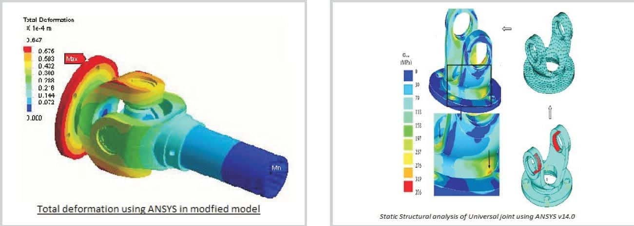
The Solution:
An assembly of the parts was created using Pro/E & the assembled model was imported to ANSYS for analysis.
The analysis was done by using different boundary conditions and selecting the SOLID-92 tetrahedral element. The stress, strain and deformation on the ANSYS model of the universal joint were checked for varying loading conditions.
The analysis revealed that the maximum stress was occurring at both the yokes of the universal joint at the middle span. The beginning location of crack corresponds to the point of highest stress. A modification of the design, by a slight increase in dimension, was suggested after analysing the parameters for different boundary conditions.
Benefits FEA Services :
- The finite element analysis revealed the exact location where the maximum stress and the maximum deformation were occurring in the part.
- The client was able to examine the exact crack propagation by the point of highest stress.
- The downtime and associated costs in physical tests and design modifications reduced considerably.
About Australian Design And Drafting Services
ASTCAD Services is a specialist firm providing engineering solutions to organisations across the AUSTRALIA.
We have extensive experience in providing concept to manufacturing and post-manufacturing solutions to clients with a team of expert design engineers, CAD professionals and simulation analysts.
Universal joint design and documentation
Universal joint design concentrates classic machine design in one assembly: contact stresses at the cross trunnions, bearing selection for the torque and articulation duty, lubrication provisions that survive the service environment, and balance requirements as speed rises. This project documented a universal joint for fabrication with the yoke, cross and bearing engineering resolved to Australian standards, tolerance schemes matched to the machining processes available, and assembly documentation covering the fits that make or break joint life.
Power transmission components like this are a recurring specialty: couplings, drive shafts, gearbox interfaces and their alignment engineering. Fabricators and plant engineers send the duty specification, and the documented design follows with the calculations attached.