DESIGN Australian Design & Drafting is one of the major Architectural CAD and Engineering Companies offering high-end Engineering Design Services. We provide extensive Engineering Design Services across all domains. Our team of Architects and Design Engineers strive to deliver high quality and optimum design solutions keeping in mind Australian Design Standards and Codes
ENGINEERING DESIGN SERVICES WE OFFER
We offer the following Engineering Design services
Architectural CAD Design Services
CAD Design and Development Drawings
Structural Design and Analysis
Mechanical CAD Design Services
Finite Element Analysis
HVAC Design Services
Plumbing Design Services
Electrical Design Services
Our Architects and Design Engineers are well acquainted with design standards applicable for each location or state. We also have a team of senior consultants apart from our in house team of Architects and Engineers. These consultants are experts with more than 10 years of experience in their respective fields. For all Mechanical CAD Design Services, Structural Design and Analysis requirements and Architectural CAD Design Projects, we confer with our consultants on the understanding of the project and assess pricing and execution plan as well. We consider your budget, project requirements, and feasibility to ensure that our design meets these needs.
“Architectural design and drafting Services” is a broad term — architectural drafting sits at its core — that includes both the technical and creative parts of the field. It means understanding building materials and shapes and designing and making buildings. Architects usually plan their work to fit both the inside and outside of a building. Still, designs can be deadly when they go against what people want and what is expected of them.
Through architectural design services, the client’s ideas come to life. The first step in these services is building planning and design. Engineers tend to care more about how things work than architects do. When people use architectural design services, they can write down their creative ideas. To succeed in this field, you’ll need to know how to use computers, understand the law, understand how engineering works, and follow building codes.
Reasons Why Good Architectural Drafting Is Crucial
Structures inside the built environment significantly affect the built environment as a whole. When putting up a new building, it’s important to think about how it will work, how long it will last, how it will look, and how it will affect the neighbourhood. The best-quality architecture will amaze and shock people with its unique and stylish design. Homes and neighborhoods that make people feel good will always be in demand. Living in a dull, boring place is a surefire way to kill your ideas and creativity.
Instances when Architectural Plans Can Be Used:
Dimensional Modelling in Building Design
Floor plans, wall sections, elevations, lighting plans, furniture designs, foundation diagrams, and roof sections are all referred to by this term.
Proficient 3D Modelling for Buildings
It can make exterior 3D models, interior 3D models, cross-sections, and fixture assemblies. Similarly, landscape architects employ it in their design processes.
Rendering in Three Dimensions for Buildings
It can produce 3D-rendered images of the outside, inside, on furniture, and off of products.
Animation and Exploration in Three Dimensions
Exterior and interior tours, as well as conceptual and industrial tours, are all part of the package.
A building plan is just a set of instructions for how to build something well. Such ideas can come from a thorough look at the site, research into the history and culture of the area where you want to build, or an analysis of how different technologies and techniques could be used to meet a wide range of practical needs.
Want to make your dream house a real place to live? Or maybe you have a great plan for making your office better? With the help of experts, all of your hopes and dreams for the infrastructure can come true. These people are trained architects who can put what you have in mind on paper.
Look online for architectural design firms with a form for entering your home’s basic plan or details like the rooms, the balcony, the style, and anything else you’d like to include. Astcad is a place where you can get Architectural Design Services. They offer 2D drawings and 3D images made on a computer with CAD software.
What is architectural drafting?
Drafters make house plans under the direction of architects, who describe the layout and materials used inside and the driveways, garden beds, fences, and roof types for the outside. These are plans for a house or another building.
Architects and engineers used to draw by hand with pencils, rulers, and protractors. Now, almost all drawings are made with a computer-aided design (CAD) program.
Architectural Design and Drafting Services
The computer-assisted design uses a computer to make a technical picture of a thing or building in three dimensions. This is more efficient and accurate than traditional drawing methods. The electronic version has more information and more options. Architectural Drafting Service uses CAD and ArchiCAD to make most of its plans and designs.
What are architectural drafting services?
Architectural drafting services involve the creation of detailed technical drawings and plans for architectural projects. These services are typically provided by architectural drafters or firms specializing in architectural drafting.
Here are some key aspects of architectural drafting services:
Drafting Architectural Plans: Architectural drafters create detailed plans, elevations, sections, and other technical drawings based on the designs provided by architects or architectural designers. These drawings serve as a roadmap for construction, showing dimensions, materials, and other specifications. CAD Drafting: Computer-aided design (CAD) software is commonly used in architectural drafting to create precise and accurate drawings. CAD allows drafters to efficiently produce and modify drawings, as well as generate 3D models and visualizations. Conversion of Design Concepts: Architectural drafters often work with architects to translate their design concepts into technical drawings that can be used for construction. This may involve refining sketches or conceptual drawings into detailed architectural plans. Detailing and Documentation: Architectural drafters add specific details to drawings, such as building components, structural elements, electrical layouts, plumbing systems, and other relevant information. These details ensure that the construction process proceeds smoothly and according to the intended design. Collaboration with Design Team: Architectural drafters collaborate closely with architects, engineers, interior designers, and other members of the design team to ensure that the drawings accurately reflect the project requirements and design intent. Code Compliance: Architectural drafters ensure that the drawings comply with local building codes, regulations, and zoning requirements. This includes incorporating necessary information for permits and approvals.
What is architecture and drafting?
Architecture and drafting are closely related fields within the broader realm of the construction and design industry. Here’s a breakdown of each:
Architecture: Architecture encompasses the planning, design, and construction of buildings and other structures. Architects are professionals trained in the art and science of designing buildings that are functional, aesthetically pleasing, and structurally sound. They consider factors such as the purpose of the building, its location, environmental impact, building codes and regulations, and the needs and preferences of the people who will use the space. Architects typically lead the design process, working closely with clients, engineers, and other stakeholders to develop conceptual designs, create detailed plans and drawings, and oversee the construction of the project.
Drafting: Drafting, also known as technical drawing or drafting, is the process of creating detailed and accurate drawings, plans, and diagrams that communicate the specifications and details of a design. Drafters use specialized software such as computer-aided design (CAD) programs to create technical drawings that show the dimensions, materials, and other essential information needed for construction or manufacturing. Drafting is a critical aspect of the design and construction process, as it provides the detailed documentation necessary for builders, fabricators, and contractors to execute the design accurately.
Claire has 10 years of experience in Revit BIM modelling, architectural documentation, and CAD conversion projects across Southeast Queensland and NSW. She has delivered NCC-compliant documentation for residential, commercial, and industrial facilities.
CAD or CAD drafting is a technique of designing complex 2D or 3D models of parts, machines, and buildings using computer-based software before enacting the actual design. Drafting a rough but abstract draft before the real work helps the designer test the product design.
How to use CAD design & drafting services in the design process?
The production support system includes components for product design and associated CAD/CAM systems. The classic design process comprises six steps: recognising design needs, problem formulation, synthesis, analysis and optimisation, evaluation, and presentation.
The best tools to use for CAD design-specific tools and techniques are CAD Designers, including Siemens NX, AutoCAD, CATIA, Solid works, Inventor, etc. You may build the world of your dreams with all these tools and cutting-edge technology.
What are the steps involved in the CAD designing and drafting service?
The significant stages of Developing CAD designing and drafting standards are
Meta Stage.
Development Stage.
Execution Stage.
The role of cad designing and drafting services in industrial product designing
It is the current trend in the field of design in contemporary times. Many significant firms outsource their CAD design and CAD design engineer rather than invest in internal infrastructure. The sole reason is that it offers a range of benefits to organisations.
A few major benefits are:
Minimal expenditure on additional equipment and labour during product design.
The reliability and professionalism of these services are way better and faster than any else.
It saves a lot of time the company will invest in brainstorming, planning, and plotting the design.
Minimise the risk of the failure of the design.
Protects the privacy of the product designs.
Saves money, and labour goes behind designing
Involvement of dedicated designers who know their work well and know how to get the result right with minimum resources and time.
In usual practice, when companies draft the design by themselves, it demands a good amount of money for a single project which sometimes churns their economy.
But you can expect many perks when you deal with Australian Designing and Drafting Services. We will save a good amount of money on CAD drafting services and CAD designing.
It is a great deal for companies trying to establish their feet in the market and for well-established companies.
These services guarantee exceptional results to any in-house workforce accessible in businesses, and they frequently do their work in a fraction of the time.
Our staff knows tier work and delivery only what the client has asked for with their designs.
Drafting & Cad Design Services Role in Industrial
Drafting and CAD (CAD Drafting) services play a crucial role in the industrial sector, providing a range of benefits that improve efficiency, accuracy, and productivity. These services involve creating detailed technical drawings and digital models of products, parts, and components used in various industries. Here’s a closer look at their role in the industrial domain:
Product Design and Development: CAD software allows industrial designers and engineers to create precise 2D and 3D models of products and components. It helps in visualising ideas, iterating designs, and conducting simulations before moving to the physical prototyping stage. This streamlines the product development process and minimises the need for physical prototypes, reducing costs and time-to-market.
Engineering Analysis and Simulation: CAD software often integrates with engineering simulation tools. Engineers can analyse and simulate the behaviour of products under various conditions, such as stress, heat, fluid flow, and electromagnetic forces. This enables them to identify potential design flaws and optimise the performance and reliability of industrial products.
Manufacturing and Prototyping: CAD drawings are used by manufacturers to create moulds, tooling, and other manufacturing processes. These detailed drawings ensure precise production, reducing the chances of errors and waste. Additionally, CAD models can be directly used in additive manufacturing (3D printing) processes, expediting prototyping and small-scale production.
Assembly and Installation Instructions: CAD software facilitates the creation of assembly instructions and technical documentation. It allows designers to illustrate step-by-step instructions, making it easier for assembly line workers to put together complex industrial systems, saving time and reducing errors.
Design Collaboration and Communication: CAD software enables real-time collaboration among team members, allowing engineers, designers, and other stakeholders to work together on the same project remotely. This streamlines communication, fosters better teamwork, and helps resolve design issues quickly.
Maintenance and Lifecycle Management: CAD models often serve as a digital twin of the physical product. During the product’s lifecycle, these models can be updated to reflect changes, improvements, and repairs. This ensures accurate documentation and aids in effective maintenance and asset management.
Regulatory Compliance and Standards: In various industries, adherence to specific standards and regulations is crucial. CAD software helps ensure that designs meet regulatory requirements by enabling designers to validate designs against industry standards before manufacturing.
Cost Reduction and Resource Optimisation: CAD services reduce the need for physical prototyping and manual drafting, saving time and resources. By identifying design issues early in the process, costly errors can be avoided, leading to cost reduction in the long run.
Retrofitting and Upgrades: For existing industrial systems or equipment that require upgrades or modifications, CAD models aid in planning and implementing retrofitting processes more efficiently and accurately.
Overall, drafting and CAD design services have revolutionized the industrial sector by facilitating faster product development, improved accuracy, reduced costs, and enhanced collaboration among different teams involved in the design and manufacturing process. It has become an integral part of modern industrial practices across various sectors, from automotive and aerospace to electronics and construction.
Summary Last but not least, the benefits involved with outsourcing Drafting services Melbourne & Perth for CAD design and drafting services have the lowest chance of risk. When you decide to outsource your design work with us, be assured that you will only get the best possible result in minimal time. We also guarantee the confidentiality of your design.
What are CAD drafting services?
CAD drafting services encompass a range of activities involving CAD Drafting (CAD) software to create, modify, or optimize technical drawings and designs. Here’s a breakdown: Creation of Technical Drawings: CAD drafting services involve creating detailed drawings of various objects, structures, or components. This can include architectural floor plans, elevation drawings, mechanical part drawings, electrical schematics, and more. These drawings are typically created based on specifications, sketches, or concepts provided by clients or engineers. Conversion of Drawings: Sometimes, existing drawings or blueprints need to be converted into digital CAD files for easier storage, editing, and sharing. CAD drafting services can involve converting hand-drawn sketches, legacy blueprints, or 2D drawings into accurate digital formats. Modification and Revision: CAD software allows for easy editing and revision of drawings. CAD drafting services often involve making changes to existing CAD drawings based on client feedback, design alterations, or project requirements. This ensures that drawings stay up-to-date throughout the design process. 3D Modeling: In addition to 2D drawings, CAD drafting services may also involve creating three-dimensional models of objects, buildings, or products. 3D modeling provides a more comprehensive understanding of the design and can be used for visualization, analysis, and simulation purposes. Rendering and Visualization: CAD drafting services may include rendering and visualization to create realistic images or animations of CAD models. This helps stakeholders visualize the final product, simulate lighting conditions, and present design concepts to clients or investors. Design Optimization: CAD drafting services can also involve analyzing CAD designs for efficiency, performance, and manufacturability. Design optimization aims to identify potential improvements and optimizations to enhance the overall quality and functionality of the design.
What is CAD design service?
CAD design services involve the use of CAD Drafting (CAD) software to create, modify, and optimize digital designs for various purposes. These services are offered by professionals or firms with expertise in CAD software and design principles. Here’s what CAD design services typically entail: Conceptual Design: CAD design services often begin with conceptualization, where ideas, sketches, or concepts are translated into digital form using CAD software. This stage involves brainstorming, sketching, and creating initial design drafts to explore different possibilities and concepts. Detailed Design: Once a concept is finalized, CAD designers work on creating detailed designs that include specific dimensions, materials, and features. This may involve creating 2D drawings, 3D models, or both, depending on the requirements of the project. Prototyping and Testing: CAD design services may also involve creating prototypes or virtual models to test the design’s feasibility, functionality, and performance. Virtual simulations and analysis tools integrated into CAD software allow designers to evaluate the design’s behavior under different conditions. Design Optimization: CAD designers optimize designs to improve efficiency, functionality, and manufacturability. This may involve refining shapes, optimizing structures, reducing material usage, or enhancing performance based on analysis and feedback. Collaboration and Communication: CAD design services facilitate collaboration and communication between designers, engineers, clients, and stakeholders. CAD software allows for easy sharing, reviewing, and commenting on design iterations, ensuring that everyone involved in the project is on the same page. Documentation: CAD design services include creating comprehensive documentation such as drawings, specifications, and technical reports. These documents serve as a reference for manufacturing, construction, or implementation of the design. Customization and Personalization: CAD design services can cater to specific needs and requirements, offering customized solutions tailored to the client’s preferences, industry standards, and project constraints.
James has 14 years of hands-on experience delivering CAD design, structural drafting, and engineering documentation across Australia’s mining, oil & gas, and manufacturing sectors. He specialises in SolidWorks, Autodesk Inventor, and AutoCAD for complex multi-discipline projects.
If you’re an engineer, drafter, or buyer of CAD services in Australia, understanding the difference between 2D and 3D drawings is fundamental. The two formats serve different purposes — and choosing the right one for your project affects cost, accuracy, and what your manufacturer can do with the file.
Quick Answer: 2D vs 3D Drawings
2D Drawing
3D Drawing / Model
Dimensions
Length + width (flat)
Length + width + depth (volumetric)
Views
Front, top, side (orthographic)
Full 3D — rotate, pan, zoom any angle
File formats
DWG, DXF, PDF
STEP, IGES, STL, SLDPRT, IPT, RVT
Main software
AutoCAD (2D), MicroStation
SolidWorks, Inventor, CATIA, Revit
Mass/volume data
❌ None
✅ Yes (solid models)
Use in manufacturing
CNC code, fabrication, shop floor
Simulation, FEA, 3D printing, CNC
File size
Small
Larger (especially assemblies)
Australian standard
AS/NZS 1100 — all drawings
AS/NZS 1100 + ISO 16792 (3D annotation)
What Is a 2D Drawing?
A 2D drawing represents an object on a flat plane using two dimensions: length and width. It communicates the geometry of a part using multiple orthographic views — typically front, top, and side — laid out on a drawing sheet per AS/NZS 1100.
Every manufactured part still needs a 2D drawing (also called an engineering drawing or technical drawing) to define tolerances, surface finish, material, and manufacturing notes — information that 3D models don’t carry natively.
What 2D drawings include
Orthographic views (front, top, side, auxiliary)
Dimensions and tolerances (bilateral, unilateral, GD&T)
Surface finish callouts (Ra values)
Material and treatment specifications
Title block (part number, revision, scale, drafter)
Section and detail views
Weld symbols (AS 2812 / AS/NZS 2980)
Bill of materials (for assemblies)
When to use 2D drawings
Workshop fabrication and machining — the shop floor works from 2D drawings
Structural steel detailing (AS 4100)
Architectural construction documentation
Electrical schematics and wiring diagrams
Council and building permit submissions
MEP coordination drawings
Converting legacy paper drawings to CAD
A typical 2D engineering drawing with front, top, and side views, tolerances, and title block — the standard deliverable for manufacturing.
What Is a 3D Drawing (3D CAD Model)?
A 3D drawing — more accurately called a 3D CAD model — represents an object in three dimensions with length, width, and depth. Unlike 2D drawings, a 3D model lets you rotate, pan, and inspect the part from any angle.
There are three types of 3D CAD models, each with different capabilities:
1. Wireframe models
The simplest 3D format — stores only vertices and edges, no surfaces or mass. Lightweight but hard to visualise and can’t be used for analysis. Mostly used as a stepping stone or reference geometry.
2. Surface models
Adds outer surfaces to the wireframe — the model looks solid but has zero thickness and no mass. Surface models can shade, colour, and texture for visualisation. Used heavily in industrial design, automotive body styling, and any complex freeform geometry. Common software: CATIA, Rhino, Alias.
3. Solid models
The most capable 3D format — stores vertices, edges, surfaces, AND mass. A solid model encloses a volume and contains material properties, enabling:
Mass properties — weight, centre of gravity, moment of inertia
The dominant solid modelling packages in Australia are SolidWorks, Autodesk Inventor, CATIA, Siemens NX, and Revit (for architecture/BIM).
A 3D solid model — the part has volume, mass properties, and can be rotated freely. It’s used to generate 2D drawings, CNC code, and 3D prints.
2D vs 3D Drawings: Which Do You Need?
Your project need
What you need
Part to be machined or fabricated by a workshop
2D drawing (with tolerances + title block)
Part to be 3D printed
3D solid model (STL export)
Structural steel — workshop fabrication
2D shop drawings (per AS 4100)
Architecture — council submission
2D drawings (floor plans, elevations, sections)
Architecture — client presentation or marketing
3D render from Revit or SketchUp
Mechanical assembly — check fit before making
3D assembly model with motion simulation
Product design — stress test before prototyping
3D solid model with FEA analysis
Conversion — paper drawing to CAD
2D DWG (and optionally a 3D model)
MEP / building services
2D and/or 3D Revit MEP model
Do 2D and 3D Drawings Work Together?
Yes — and this is how most professional CAD workflows operate. The 3D solid model is built first, then 2D drawings are generated from it automatically. When the 3D model changes, the 2D drawing updates. This model-based design (MBD) approach eliminates the risk of drawings being out of sync with the model.
The 3D model handles: design intent, simulation, interference checking, and CNC programming. The 2D drawing handles: tolerances, surface finish, annotations, and workshop instructions. Both are needed for a complete deliverable.
File Formats: 2D vs 3D
Format
Type
Used for
DWG / DXF
2D (and 3D wireframe)
AutoCAD drawings — most common 2D exchange format
PDF
2D (print/view)
Sharing drawings for review and council submission
STEP (.stp)
3D solid / surface
Universal 3D exchange — works in any CAD software
IGES (.igs)
3D solid / surface
Older exchange format — still widely used
STL
3D surface (mesh)
3D printing only
SLDPRT / SLDASM
3D solid (SolidWorks)
SolidWorks native parts and assemblies
IPT / IAM
3D solid (Inventor)
Autodesk Inventor native
RVT
3D BIM (Revit)
Architecture, structural, MEP building models
What is the main difference between 2D and 3D drawings?
A 2D drawing shows an object on a flat surface using two dimensions (length and width) — typically as orthographic views (front, top, side). A 3D drawing adds depth, creating a volumetric model you can view from any angle. 2D drawings define tolerances, surface finish, and manufacturing instructions. 3D models contain mass, volume, and enable simulation, rendering, and 3D printing. In practice, both are used together: the 3D model is built first, then 2D drawings are generated from it.
Which is better for manufacturing — 2D or 3D drawings?
Manufacturing requires both. The workshop needs a 2D drawing with explicit tolerances (e.g. ±0.05mm), surface finish callouts (Ra 1.6), material specifications, and title block — information that 3D models don’t fully communicate on their own. The 3D model is used to generate CNC toolpaths, check fit in assemblies, and 3D print prototypes. Sending only a 3D model to a workshop without a 2D drawing is risky because the machinist has no tolerance or finish guidance.
What CAD software creates 2D drawings vs 3D models?
For 2D drawings: AutoCAD is the industry standard, used by most Australian engineers and drafters. MicroStation is common in infrastructure and government. For 3D solid modelling: SolidWorks and Autodesk Inventor dominate Australian manufacturing and fabrication. CATIA is used in aerospace and automotive. Revit handles architecture, structural, and MEP in 3D (BIM). Most 3D packages generate 2D drawings directly from the model — SolidWorks produces DWG/PDF drawing sheets, Inventor produces idw/DWG, Revit produces A-series sheet sets.
Is a 3D model the same as a 3D drawing?
Not exactly. A 3D drawing usually refers to a 2D representation that conveys 3D depth — like an isometric view or a perspective sketch on paper. A 3D model is a digital object with actual three-dimensional geometry stored in a CAD file (STEP, SLDPRT, IPT, etc.). In engineering practice, ‘3D drawing’ is informally used to mean a 3D CAD model. The distinction matters when specifying deliverables: a ‘3D model’ in STEP format is a specific, unambiguous request; a ‘3D drawing’ could mean different things to different people.
Need 2D drawings, 3D models, or both for your Australian project? ASTCAD’s drafting team works in AutoCAD, SolidWorks, Inventor, Revit, CATIA and more — delivering AS/NZS 1100-compliant drawings and STEP/IGES models to any specification. Get a free quote.
How We Work: Turnaround, Revisions and Confidentiality
Knowing the difference between 2D and 3D is one thing; knowing which one your project should be documented in, and what happens once you hand it over, is another. This is how a drafting scope actually runs at ASTCAD.
Which one your project needs
2D is enough when the geometry is prismatic, the fabricator works from dimensioned views, and no downstream simulation or clash checking is required — most sheet metal, structural steel detailing and single-discipline layouts.
3D earns its cost when parts must assemble, when the model feeds CNC or additive manufacture, when clash detection across disciplines matters, or when the client needs visualisation for approval.
Both, in sequence is the most common real answer: model in 3D, then derive the 2D fabrication set from it, so the drawings can never drift out of step with the model.
Turnaround
Lead time is driven by input quality far more than by drawing count. A clean 3D model needing 2D extraction and annotation moves quickly. Marked-up PDFs, photographs or a physical sample needing reverse engineering add a modelling phase at the front of the programme. Tell us the deadline at enquiry stage — where a set is genuinely time-critical we will say so before starting rather than after.
Revisions
Every drawing carries a revision block, and revisions are issued as a clouded and numbered set rather than a silent replacement, so your fabricator can see exactly what changed. Design changes originating from your side are scoped and confirmed before work resumes; corrections to our own output are not chargeable.
Confidentiality and file ownership
We work under NDA as standard, and will sign yours rather than insisting on ours. Native files and drawings belong to you on completion — models are delivered in the source format as well as neutral STEP or IGES, so you are never locked to our toolchain. Client drawings are not used as portfolio material without written permission.
What to send with an enquiry
Whatever documentation exists — models, drawings, PDFs, sketches or photographs
The end use: fabrication, machining, tender, approval or visualisation
The standard the set must satisfy, if one applies — most Australian technical drawing work is called up against AS 1100 (Standards Australia)
Deliverable formats your downstream contractors need
James has 14 years of hands-on experience delivering CAD design, structural drafting, and engineering documentation across Australia’s mining, oil & gas, and manufacturing sectors. He specialises in SolidWorks, Autodesk Inventor, and AutoCAD for complex multi-discipline projects.
Computer Aided Design (CAD) & Drafting Services in Australia
ASTCAD provides professional computer aided design (CAD) and drafting services to engineering, construction and manufacturing clients across Australia. Our CAD services cover all major disciplines — mechanical, structural, architectural, civil and electrical — using the industry’s leading software packages with offices in Brisbane, Sydney, Melbourne, Perth and Gold Coast.
What Is CADD? Computer Aided Design and Drafting Explained (2026 Guide)
Computer-aided design and drafting (CADD)
Computer-aided design and drafting (CADD) is the process of using a computer with CADD software for design and drafting applications. Software is the program or instructions that enable a computer to perform specific functions to accomplish a task. CADD refers to the entire range of design and drafting with the aid of a computer, from drawing basic 2-D objects to preparing complex 3-D models and animations. CAD is the acronym for computer-aided design and a common reference to computer-aided drafting. Computer-aided design and computer-aided drafting refer to specific aspects of the CADD process.
CADD offers solutions to most engineering drawing and design problems, and it allows for increasingly complex projects. Several industries and most disciplines related to engineering and architecture use CADD. Most engineering firms and educational institutions that previously used manual drafting practices have evolved to CADD. Professionals have come to rely on the power and convenience of CADD in all aspects of design and drafting. CADD systems include tools to accomplish any drawing and design requirement, such as preparing the 3-D model of a home shown in Figure.
The CADD workstation
The CADD workstation consists of a variety of computer hardware. Hardware includes the physical components of a computer system, such as the computer, monitor, keyboard, mouse, and printer. The figure shows a modern CADD work-station. A CADD workstation relies on a computer for data processing, calculations, and communication with peripheral equipment. A peripheral is an external computer hardware device that uses the computer to perform functions that the computer cannot handle. Peripherals provide input, output, and storage functions and services. Input means to put information into the computer that the computer acts on in some way. Input comes from devices such as the keyboard, a mouse or similar input device, or a digitizer. Output refers to information that the computer sends to a receiving device such as a monitor, a plotter, or a printer. Storage refers to disks and drives that allow the operator to store programs, files, symbols, and data.
CADD software products
The modern CADD workstation is powerful, inexpensive, and supports sophisticated CADD software. Many CADD software manufacturers exist, and numerous products are available to meet industry needs. Some CADD software is general purpose and can apply to any discipline. For example, Autodesk, Inc. produces AutoCAD for 2-D and 3-D design and drafting.
Other products focus on a specific CADD technology, industry, or discipline, such as drawings or models of mechanical parts and assemblies or those for architectural, civil, or structural engineering projects.
For example, Dassault Systèmes SolidWorks Corp. offers SolidWorks for 3-D solid modelling and 2-D drafting that is common in the manufacturing industry. Software specifically designed for CADD in the manufacturing industry is sometimes referred to as mechanical computer-aided design (MCAD) software. Some CADD programs support expanded, third-party, or add-on utilities intended to increase system usefulness for specifi c applications. The CADD software industry changes constantly. Software manufacturers frequently update existing products or combine, change program names, or eliminate programs to adapt to the rapidly evolving CADD market. Software updates typically include additional and refined tools, increased software stability, and graphical user interface (GUI) enhancements.
Computer Aided Design and Drafting
The interface describes the items that allow you to input data to and receive outputs from a computer system. The GUI provides the on-screen features that allow you to interact with a software program. New products regularly emerge to respond to innovative technology and project requirements. Larger software manufacturers, such as Autodesk Inc., Dassault Systèmes, Parametric Technology Corporation, and Siemens PLM Solutions hold the greatest number of CADD users, and they traditionally have the ability to expand their products and acquire smaller software companies or existing software.
ASTCAD provide excellent service for CAD Design and Drafting. Contact Us for more info
What is computer-aided design and drafting?
Computer-aided design and drafting (CADD), also known as computer-aided design (CAD), refers to the use of computer software to assist in the creation, modification, analysis, or optimization of designs for a wide range of applications. CAD software allows designers, engineers, architects, and other professionals to create precise 2D drawings or 3D models of objects, buildings, mechanical parts, electrical circuits, and more.
What is computer aided drafting CAD used for?
Computer-aided drafting (CAD) is used in architecture and construction, mechanical engineering, product design and manufacturing, electrical and electronic systems, interior design, urban planning, and aerospace and automotive industries.
James has 14 years of hands-on experience delivering CAD design, structural drafting, and engineering documentation across Australia’s mining, oil & gas, and manufacturing sectors.
A CAD drafter (also called a CAD technician, CAD designer, or drafting technician) is a technical professional who uses computer-aided design software to produce precise engineering drawings, models, and technical documentation. In Australia, CAD drafters work across mechanical, structural, civil, architectural, and electrical disciplines — translating engineer and architect designs into detailed, buildable drawings.
What Does a CAD Drafter Do?
The day-to-day work of a CAD drafter varies by discipline, but typically includes:
Producing 2D engineering drawings from sketches, specifications, or 3D models (detail drawings, assembly drawings, general arrangement drawings)
Building 3D CAD models in SolidWorks, Inventor, Revit, or AutoCAD
Adding dimensions, tolerances, material callouts, weld symbols, and notes to drawings
Coordinating with engineers, architects, and fabricators to resolve drawing queries
Updating drawings to incorporate design revisions, issuing revision-controlled drawing sets
Converting old manual or paper drawings to CAD format
Producing shop drawings and fabrication drawings for manufacture
Maintaining drawing registers and document control systems
CAD Drafter Education and Qualifications in Australia
Qualification
Level
Duration
Outcome
Certificate III in Engineering — Technical (MEM30219)
VET / TAFE
1–2 years
Entry-level drafter — 2D AutoCAD focus
Certificate IV in Engineering (MEM40119)
VET / TAFE
1–2 years
Mid-level — broader engineering context
Diploma of Engineering — Technical (MEM50219)
VET / TAFE
2 years
Senior drafter / junior designer level
Advanced Diploma of Engineering (MEM60119)
VET / TAFE
2–3 years
Design engineer / project lead level
Bachelor of Engineering Technology
University
3 years
Engineering technologist — can progress to CPEng
Bachelor of Engineering (Honours)
University
4 years
Professional engineer — may start as drafter
In practice, most Australian CAD drafters enter through TAFE — the Certificate III or IV in Engineering is the most common pathway. Software training (AutoCAD, SolidWorks, Revit) is typically learned through short courses, on-the-job training, or vendor-specific certification programs. There is no licensing requirement to work as a CAD drafter in Australia, though Engineers Australia membership and CPEng registration apply to the engineers who sign off drawings.
CAD Software Skills for Australian Drafters
Software
Discipline
Employer demand (AU)
AutoCAD
All disciplines — 2D drafting
Very High
Revit
Architecture, structural, MEP — BIM
Very High
SolidWorks
Mechanical, manufacturing
High
Autodesk Inventor
Mechanical, manufacturing
High
Civil 3D
Civil engineering, infrastructure
High
MicroStation
Infrastructure, government, Pilbara resources
Medium-High
12D
Civil engineering, surveying
Medium
CATIA
Aerospace, automotive, defence
Medium
Tekla Structures
Structural steel detailing
Medium
ArchiCAD
Architecture (smaller firms)
Low-Medium
CAD Drafter Salary in Australia (2026)
Level
Experience
Typical salary range (AUD)
Junior CAD drafter
0–2 years
$55,000 – $70,000
Intermediate CAD drafter
2–5 years
$70,000 – $90,000
Senior CAD drafter / lead
5–10 years
$90,000 – $110,000
CAD designer / principal
10+ years
$110,000 – $130,000+
Contract drafter (daily rate)
Varies
$350 – $650/day
Salaries vary significantly by location (Perth and Darwin typically pay 10–20% above Brisbane/Sydney/Melbourne for resource-sector roles), discipline (mechanical and structural tend to pay more than architectural), and the specific software stack demanded.
Job Opportunities for CAD Drafters in Australia
CAD drafters are employed by engineering consulting firms, architectural practices, construction companies, mining and resources companies, manufacturers, government agencies, and specialist drafting firms like ASTCAD. The strongest demand is currently in:
Structural steel detailing — driven by construction activity across major cities and resources infrastructure
Revit BIM coordination — tier-1 contractors now mandate BIM on most major projects
Civil infrastructure — roads, rail, water treatment, and renewable energy projects
Mining and resources — particularly in Western Australia (AutoCAD, MicroStation)
Defence industry — AUKUS and major defence procurement driving demand in Adelaide and Brisbane
James has 14 years of experience delivering CAD design, structural drafting, and engineering documentation across Australia’s mining, oil & gas, and manufacturing sectors.
Patent drawings turn inventions into protectable IP, and the success of a company often relies on the integrity of its employees. Products are normally the result of years of research, engineering, and development. This is referred to as the intellectual property of the company. Protection of intellectual property can be critical to the success of the company in a competitive industrial economy. This is why it is very important for employees to help protect design ideas and trade secrets. Many companies manufacture their products in strict, secure, and secret environments. You will often find proprietary notes on drawings that inform employees and communicate to the outside world that the information contained in the drawing is the property of the company and is not for use by others.
Software Piracy
Software piracy is the unauthorized copying of software. Most software licenses support use at one computer site or by one user at any time. When you buy software, you become a licensed user. You do not own the software. You are allowed to make copies of the program for backup purposes, but it is against the law to give copies to colleagues and friends. Software companies spend a lot of money creating software programs for your professional and personal applications. Each new release usually provides you with improved features and more efficient use. When you use software illegally, you hurt everyone by forcing software companies to charge more for their products. Ethically and professionally, use software legally and report illegal use when observed.
Copyrights
A copyright is the legal rights given to authors of original works of authorship. The Australian Constitution establishes copyright and patent law and empowers the federal government to promote the progress of science and useful arts, by securing for limited times to authors and inventors the exclusive right to their respective writings and discoveries. Copyrights control exclusively the reproduction and distribution of the work by others. In Australia, published or unpublished works that are typically copyrightable include:
Literary works, including computer programs and
Musical works, including any accompanying
Dramatic works, including any accompanying
Pantomimes and choreographic
Pictorial, graphic, and sculptural
Motion pictures and other audiovisual
Sound
Architectural works and certain other intellectual
Intellectual Property Rights and Patent Application
A patent for an invention is the grant of a property right to the inventor, issued by the IP AUSTRALIA. The term of a new patent is 20 years from the date on which the application for the patent was filed in Australia or, in special cases, from the date an earlier related application was filed, subject to the payment of maintenance fees. The IP AUSTRALIA patent grants are effective only within Australia. The patent law states, in part, that any person who “invents or discovers any new and useful process, the machine, manufacture, or composition of matter, or any new and useful improvement thereof, may obtain a patent,” subject to the conditions and requirements of the law.
The patent law specifies that the subject matter must be “useful.” The term useful refers to the condition that the subject matter has a useful purpose and must operate. You cannot patent laws of nature, physical phenomena, and abstract ideas. A complete description of the actual machine or other subject-matter is required to obtain a patent.
The IP AUSTRALIA offers standard and innovation patent applications. A standard patent application is for the full patent, which lasts 20 years. The innovation patent application is for a temporary patent that lasts for one year.
Standard Application for a Patent
According to the IP AUSTRALIA, a standard application for a patent is made to the assistant commissioner for patents and includes:
a written document that has a specification and an oath or declaration,
a drawing in those cases in which a drawing is necessary, and
the filing fee.
All application papers must be in the English language, or a translation into the English language is required. All application papers must be legibly written on only one side by either a typewriter or mechanical printer in a permanent dark ink or its equivalent in portrait orientation on flexible, strong, smooth, nonshiny, durable, white paper. Present the papers in a form having sufficient clarity and contrast between the paper and the writing to permit electronic reproduction. The application papers must all be the same size, either 21.0 cm by 29.7 cm (DIN size A4) or 21.6 cm by 27.9 cm (81¤2 3 11 in.). Application documents must have a top margin of at least 2.0 cm (3⁄4 in.), a left-side margin of at least 2.5 cm (1 in.), a right- side margin of at least 2.0 cm (3⁄4 in.), and a bottom margin of at least 2.0 cm (3⁄4 in.), with no holes made in the submit- ted papers. It is also required that the spacing on all papers be 11¤2 or double spaced, and the application papers must be numbered consecutively, centrally located above or below the text, starting with page 1. All required parts of the application must be complete before sending the application, and it is best to send all of the elements together. The IP AUSTRALIA numbers all applications received in serial order and the applicant will be informed of the application serial number and filing date by a filing receipt.
Innovation Application for a Patent
If you want protection for an invention with a short market life that might be superseded by newer innovations, such as computer-based inventions, an innovation patent is worth considering.
An innovation patent lasts up to eight years and is designed to protect inventions that do not meet the inventive threshold required for standard patents. It is a relatively quick and inexpensive way to obtain protection for your new device, substance, method or process.
The innovation patent requires an innovative step rather than an inventive step. An innovative step exists when the invention is different from what is known before, and the difference makes a substantial contribution to the working of the invention. The innovation patent protects an incremental advance on existing technology rather than being a groundbreaking invention.
An innovation patent is usually granted within a month of filing the complete application. This is because there is no examination before it is granted.
An innovation patent is only legally enforceable if it has been examined by us and found to meet the requirements of the Patents Act 1990, and has been certified. Examination of an innovation patent will only occur if requested by the patentee, a third party or if the Commissioner of Patents decides to examine the patent. The patentee will not be required to pay for examination until it is requested.
Phase-out of the innovation patent
The Australian Government has begun the process of phasing out the innovation patent with the passing of legislative amendments. This means:
The last day you can file a new innovation patent will be 25 August 2021.
Existing innovation patents that were filed on or before 25 August 2021 will continue in force until their expiry. This will ensure current rights holders are not disadvantaged.
The Government remains committed to dedicated support services to help small and medium enterprises (SMEs) navigate the intellectual property (IP) system. Australian SMEs will receive further dedicated support, with an SME case management service, the SME fast track service, a dedicated outreach program and online portal, to be launched as the innovation patent is phased out over the next 18 months.
The quick guide to innovation versus standard patents
Innovation patent
Standard patent
Your invention must:
Be new, useful and involve an innovative step.
Be new, useful and involve an inventive step.
The application should include:
A title, description, up to five claims, drawings (if applicable), an abstract and forms.
A title, description, any number of claims, drawings (if applicable), an abstract and forms.
A patent is granted if:
The application satisfies formality requirements (note: a ‘granted’ innovation patent cannot be enforced unless examined).
The application is examined and found to satisfy the relevant requirements of the Patents Act 1990.
Examination:
Optional. The examination can be requested by you or anyone else.
Mandatory. The relevant requirements of the Patents Act 1990 must be met before a patent is granted. Can only be requested by the applicant.
Certification:
Is given if the innovation patent complies with the relevant requirements of the Patents Act 1990 in the examination. Only after certification can the patent be enforced.
N/A
Publication in the Australian Official Journal of Patents:
At grant and again at certification.
Eighteen months from earliest priority date and again at acceptance.
Protection period:
Up to eight years if annual fees are paid.
Up to 20 years if annual fees are paid (or up to 25 years for pharmaceuticals).
How long does the process take?
Approximately one month for the grant. Six months for examination if you make a request.
Six months to several years depending on circumstances.
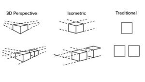
There is no requirement for a specific number of views. However, you must provide sufficient views to fully display your design, which usually requires a number of views. We prefer traditional views (front, side and top) but will also accept perspective or isometric views. (See image).
All views must show exactly the same design. This particularly applies to colour, as colour is usually a visual feature of the design.
Key points for drawings
Drawings should:
be accurately drawn, not sketches, with well-defined line-work
only show the design in question and no descriptive wording or dimensions. However, labelling of views such as ‘perspective view’ or ‘rear views’ is acceptable
on A4 size paper if lodged by post
use broken or dashed lines when highlighting:
elements of the product other than those bearing the visual features of the design
parts of the design that are referred to in the statement of newness and distinctiveness
boundaries, such as a pattern applied to part of a surface, stitching and perforations
features that establish an environmental context.
Shading and cross-hatching can be used to show a visual feature of the design.
Key points for photographs or digital images
Photographs or digital images should:
be clear originals
show the product against a plain contrasting background and avoid matter not relevant to the design
be A4 or mounted on A4 white paper if lodged by post.
Other details
If it’s a multiple design application, then each design should be clearly indicated, with each design shown on a separate sheet.
Complex products
Sometimes a design is applied to a part of a complex product, and that part can be readily assembled and disassembled from that product. If the component part qualifies as a product, then broader protection may be gained by defining this as a stand-alone part.
Trademarks
According to the IP AUSTRALIA publication Basic Facts About Registering a Trademark, a trademark is a word, phrase, symbol or design, or combination of words, phrases, symbols, or designs that identifies and distinguishes the source of the goods or services of one party from those of others. A service mark is the same as a trademark except that it identifies and distinguishes the source of a service rather than a product. Normally, a mark for goods appears on the product or on its packaging, whereas a service mark appears in advertising for services. A trademark is different from a copyright or a patent. As previously explained, a copyright protects an original artistic or literary work, and a patent protects an invention.
Trademark rights start from the actual use of the mark or the filing of a proper application to register a mark in the AUSTRALIA stating that the applicant has a genuine intention to use the mark in commerce regulated by the AUSTRALIA. Federal registration is not required to establish rights in a mark, nor is it required to begin use of a mark. However, federal registration can secure benefits beyond the rights acquired by just using a mark. For example, the owner of a federal registration is presumed to be the owner of the mark for the goods and services specified in the registration and to be entitled to use the mark nationwide. Generally, the first party who either uses a mark in commerce or files an application in the AUSTRALIA has the ultimate right to register that mark. The authority of the AUSTRALIA is limited to determining the right to register. The right to use a mark can be more complicated to determine, particularly when two parties have begun use of the same or similar marks without knowledge of one another and neither has a federal registration. Only a court can make a decision about the right to use. Federal registration can provide significant advantages to a party involved in a court proceeding. The AUSTRALIA cannot provide advice concerning rights in a mark. Only a private attorney can provide such advice.
Intellectual Property Rights and Patent
Trademark rights can last indefinitely if the owner continues to use the mark to identify its goods or services. The term of federal trademark registration is ten years, with ten-year renewal terms. However, between the fifth and sixth year after the date of initial registration, the registrant must file an official paper giving certain information to keep the registration alive. The registration is cancelled if this is not done. Please confirm specific trademark details and requirements with the AUSTRALIA.
James has 14 years of hands-on experience delivering CAD design, structural drafting, and engineering documentation across Australia’s mining, oil & gas, and manufacturing sectors. He specialises in SolidWorks, Autodesk Inventor, and AutoCAD for complex multi-discipline projects.
There has been a new trend in CAD designing world for a 3D modelling for complex design and CAD design platform has evolved so much that 2D drawings become the by-product of 3D modelling.
2D drawings are easy to generate but engineers prefer 3D models for complex applications and design generation. When both are easily achievable, they also are a choice of avoiding catastrophe in the longer run. It basically demands foresight to decide and avail a smooth function of fabrication part of the engineering project and business applications on later stages. Engineering documentation is at the heart of the long, storied history of technical draftsmanship. The objective back then is no different from today’s challenge: represent an engineering design in the most accurate and concise way possible. Distilling the 3D reality we live in onto sheets of paper involved a carefully considered system of dimensioning and orthographic projections. These days, they might be referred to as 2D Drawings (which is a redundant term if you think about it). The system worked then and it works now. Those who are well-trained in these classical methodologies have difficulty understanding why there should be anything else. Why fix what ain’t broke?
To think that 2D drawing has been trashed out with the advent of 3D CAD modelling is far from reality. 2D drafting still has a very prominent place amongst the industrial product designers, and they have their own reasons for it.
2D is the best option when you are facing tight deadlines and the designs are to be developed for a single component or a single part. Basic geometries are easy to generate in 2D CAD sketching tools and are quick. They are intriguing when the drawings do not need any functionalities of 3D and require less space. A designer of any skill sets can easily work with 2D CAD and nearly any desktop will support 2D drafting.
For a crystal clear usage, engineers still use 2D drafts for fabrication drawings, plans, elevation, sectional drawings and shop floor drawings for fabrication. In fact, it is quite surprising that approximately 30% of engineering design firms and design engineers still use paper to design the initial concept sketched and then resort to 2D CAD for digitization.
Despite these benefits, there are a few drawbacks of using 2D. When sectional views are generated in 2D, updating them is time-consuming and also prone to errors. Also, 2D CAD software does not have rendering capabilities. This means, it involves an additional step to export and convert designs into 3D models before rendering.
So for a fact, just to save time, you are doing two more steps, exporting and converting before any other action is being taken- literally two for one. It reduces productivity and lengthens the designing cycle. For these reasons, industry-wide shift to 3D modelling is witnessed among mechanical and industrial product design engineers.
In contrast, the classic engineering drawing is fraught with limitations:
Interpretation Issues: A properly executed drawing shouldn’t be subject to misinterpretation, but that skill is starting to become something of a lost art. Unclear depictions can be problematic (i.e. which surface did that leader line touch?). More disturbingly, errors can easily escape detection. Sure, most of that can be mitigated with carefully defined GD&T, but that too seems to be a fading skill. PMI improves upon these limitations by clearly associating surfaces and endpoints and providing validation that such dimensions do indeed make logical sense.
Manual Inspection: Drawings necessitate reinterpretation by humans on the other side of the manufacturing lifecycle. It’s another way to introduce error: the botched inspection. PMI sets the stage for automated inspection, accelerating manufacturing processes while simultaneously improving quality.
Time is Money: This is where drawings go for the BRAINS… Simply put, in today’s constantly accelerating demand to crank out the engineering in less time, drawings just take too long. Increased market pace demands more efficient processes. An engineer who’s spent considerable time defining a model, shouldn’t have to spend much longer documenting it. The days of modelling something then throwing it over a fence to lay it out are over. These two aspects of the design must occur simultaneously, and this ultimately is only possible with the model-based definition.
3D Models: Make a three-way profit
As business needs became bigger, design cycles were required to get shorter and engineering lead time needed to get easier and without errors; this is when more and more engineers started resorting to 3D CAD software. The advantage of using 3D CAD over 2D CAD is that it reduces the design cycle time to almost half and gives a competitive advantage to designers as well as fabricators by accommodating alterations, much fasters.
Another takeaway with 3D CAD is that it offers excellent workaround while generating rapid prototypes. And with additive manufacturing gaining momentum over traditional manufacturing practices, 3D CAD is the way to adapt to easily transform designs into tangible products.
Since additive manufacturing is a process that eliminates material cutting, it has a dramatic control over scrap produced. This is one among many reasons why this phenomenon has gained traction for every fabricator in any industry – be it industrial sheet metal tools, automotive, building products, furniture or any other that one can think of.
Such a paradigm shift makes it even more important than ever to adopt 3D CAD and drop 2D drafting process for saving material, directly targeting to increase their profits and connects the digital thread opportunity directly with the designs.
2D Drawing or 3D Model platform for CAD Designing
Other than these three major benefits, 3D CAD usually offers more functionality to the user. These functionalities encompass 3D arrays, special views, referencing and much more. But at times these are too many for generating basic part models like line-types, line-weights, and other form features are good to go. In such times, it feels that 2D drawings should be preferred instead of 3D.
Also because since 3D CAD is advanced, licensing is much expensive and renewing it each time the software company rolls-out new version, [not to mention it happens almost every year] it costs heavily to designers. Thus, it is much needed to weigh your needs of design requirements and analyse the cost you are paying for it.
By now, you must have realised that, on the contrary to popular belief, there will be times when you’ll find 2D CAD to be the need of the hour and not 3D models. While during the other times, you’ll find your designing world revolving in the three dimensions of 3D CAD models, whatever be your need – fabrication, design intent clarity or profits – to avoid catastrophe and binge working at the last moment. The hitch is that you select the one that addresses most of your needs since there isn’t any single CAD system that will address all your design and fabrication needs.
Which is better AutoCAD 2D or 3D?
The choice between AutoCAD 2D and 3D depends on your specific needs and the nature of your projects. Here’s a breakdown to help you decide: AutoCAD 2D: Best for projects that primarily involve drafting and design in two dimensions. Ideal for creating floor plans, schematics, technical drawings, and layouts. Offers precision and efficiency for tasks such as creating architectural plans, electrical diagrams, and mechanical drawings. Generally easier to learn and navigate for beginners compared to 3D. AutoCAD 3D: Suitable for projects that require modeling and visualization in three dimensions. Useful for creating realistic renderings, solid models, assemblies, and prototypes. Enables designers and engineers to explore spatial relationships, simulate designs, and identify potential issues before production. Provides a more immersive and comprehensive representation of objects compared to 2D drawings.
What software converts 2D drawings to 3D models?
There are several software options available for converting 2D drawings to 3D models. Some popular ones include: Autodesk Fusion 360: Fusion 360 allows you to import 2D sketches and then extrude, revolve, or loft them into 3D models. It’s widely used in the engineering and product design industries. SolidWorks: SolidWorks offers powerful tools for converting 2D sketches into 3D models. It’s commonly used in mechanical design and engineering. SketchUp: SketchUp is known for its intuitive interface and is often used by architects and designers. While it’s primarily a 3D modeling tool, it also supports importing 2D drawings for reference or conversion. AutoCAD: AutoCAD is a versatile CAD software that supports both 2D drafting and 3D modeling. You can import 2D drawings and use them as a basis for creating 3D models. Rhino 3D: Rhino is popular among designers and architects for its flexibility in creating both 2D and 3D designs. It supports importing 2D drawings and then transforming them into 3D models.
James has 14 years of hands-on experience delivering CAD design, structural drafting, and engineering documentation across Australia’s mining, oil & gas, and manufacturing sectors. He specialises in SolidWorks, Autodesk Inventor, and AutoCAD for complex multi-discipline projects.
When you make the decision to build a new home, there are a lot of things to consider:
Neighbourhood
Accessibility
Land or Area
Budget / Capital
No matter where you end up, perhaps the most important decision you make is that who will be the architect. If you haven’t worked with one before, you may wonder whether your project really requires an architect, most especially if it will be your personal residence.
How to Hire the Right Architect
Hiring an architect is critical for any building project to be successful. The architect is the source of the outcome, and he or she will handle a number of duties. Among them, helping clients explore what appeals to them aesthetically and what they require functionally, coordinating teams of design, engineering and construction professionals and sorting through the maze of building codes and zoning requirements to ensure projects are built the way they were planned.
Some people thought they could design their dream home on their own. And in the end they will just find that it’s a big mistake..
The professional architect is the one who has the proper education, training, experience, and vision to guide us through the entire design and construction process;
help us define what we want to build,
help us get the most for our construction.
Should be a “Problem Solver” That is what architects are trained to do, solving problems in creative ways. With their broad knowledge of design and construction, architects can show alternative options we might never think of on our own.
Professional interpreters of client’s dreams, visions, and objectives
Explorers of all possibilities
Studying and responding to the site and its environment
Home Design Translators that will exceed expectations
Should be a “Finance Specialist” (building construction)
An architect pays for his own way through the
lot selection,
design,
construction documents,
bidding and negotiation,
the construction phase of a custom residence project.
An architect’s input can save the owner’s money and/or add value to the project.
Because a well-conceived project can be built more efficiently and economically. Architects plan projects with us. As your ideas evolve, changes can be made on paper, much less expensively than when construction is going on. Though 3D Architectural Renderings also make it easier for the contractor to accurately price and build the project.
How to Hire the Right Architect
Energy-efficient buildings can save money on fuel bills down the road. An architect can design a building to maximise heating from the sun and let in natural light, thus reducing heating, cooling, and electric bills over time.
Can work with the budget and help us select the appropriate materials and workmanship at a fair price. Architects develop the drawings and specifications to help us get bids for construction that are based on our requirements.
Can help us choose materials and finishes that are durable as well as saving on frequent maintenance and replacement costs. Architects work to stay abreast of advances in roofing, brickwork, floor tiling, paint finishes, etc. Their familiarity with the full range of materials enables them to suggest the appropriate materials for the project.
Good design sells. A well-designed house has a higher resale value. A well-designed store draws customers. A well-designed work environment attracts employees and increases productivity.
Architects are like Machines = Easy Life
The building is a long process that is often messy and disruptive, particularly if you are living or working in the space under construction. They have an all the ideas that will make us contented on the design they offered. The architect looks out on our interests and they try to find ways to make that process go smoothly.
ASTCAD provide excellent service for CAD Design and Drafting. Contact Us for more info.
How do I choose the right architect?
Choosing the right architect is crucial for the success of your project, whether it’s designing a new home, renovating an existing one, or planning a commercial building. Here are some steps to help you select the right architect: Define Your Needs: Before you start searching for an architect, clarify your project requirements. Consider the type of building you want, your budget, timeline, desired style, and any specific features or requirements. Research Architects: Look for architects who have experience and expertise in projects similar to yours. You can start by asking for recommendations from friends, family, or colleagues who have worked with architects before. Additionally, you can search online directories, review websites, or professional organizations such as the American Institute of Architects (AIA) to find qualified architects in your area. Review Portfolios: Once you have a list of potential architects, review their portfolios to see examples of their past work. Pay attention to the style, quality, and diversity of their designs. This will help you assess whether their design aesthetic aligns with your vision for your project. Check Credentials and Experience: Verify the architect’s credentials, such as their education, licensure, and professional affiliations. It’s also essential to consider their experience level and track record of successfully completed projects. Look for architects who have a reputation for delivering high-quality work and meeting client expectations. Meet and Interview Candidates: Schedule meetings or interviews with your top architect candidates to discuss your project in detail. Use this opportunity to ask questions about their approach to design, project management process, communication style, and fees. Pay attention to how well they listen to your needs and whether you feel comfortable communicating with them. Evaluate Compatibility: Consider the architect’s personality, communication style, and compatibility with your own preferences and working style. Since you’ll be collaborating closely throughout the design and construction process, it’s essential to choose someone you can trust and communicate effectively with. Check References: Ask the architect for references from past clients and follow up with them to inquire about their experience working with the architect. This can provide valuable insights into the architect’s professionalism, communication, reliability, and ability to deliver results. Review Contracts and Fees: Before making a final decision, carefully review the architect’s contract, including the scope of services, fee structure, and any additional expenses. Make sure you understand the terms and conditions outlined in the contract before signing.
Why do you hire an architect?
Hiring an architect offers numerous benefits throughout the design and construction process: Design Expertise: Architects are trained professionals with expertise in spatial design, aesthetics, and functionality. They can translate your ideas and requirements into creative and innovative design solutions that maximize the potential of your space. Problem Solving: Architects are skilled problem solvers who can anticipate challenges and find solutions to complex design issues. Whether it’s navigating zoning regulations, optimizing energy efficiency, or addressing structural concerns, architects can help overcome obstacles and ensure your project’s success. Code Compliance: Architects have a thorough understanding of building codes, regulations, and permitting requirements. They can ensure that your project complies with all applicable codes and standards, helping you avoid costly delays or legal issues down the line. Cost Management: Architects can help you establish a realistic budget for your project and identify cost-saving opportunities without compromising on quality or design integrity. They can also assist in obtaining competitive bids from contractors and managing construction costs throughout the project. Quality Assurance: Architects act as advocates for their clients, overseeing the construction process to ensure that the project is built according to the approved design and specifications. They can conduct site visits, review contractor work, and address any issues that arise during construction to maintain quality and consistency. Creative Vision: Architects bring a fresh perspective and creative vision to your project, exploring design possibilities and incorporating innovative ideas that you may not have considered on your own. They can help you achieve a unique and personalized design that reflects your style and preferences. Coordination and Collaboration: Architects serve as liaisons between you, the client, and other members of the project team, including engineers, contractors, and interior designers. They facilitate communication, coordinate workflow, and ensure that everyone is working towards the same goals, fostering a collaborative and cohesive project environment. Value Enhancement: Investing in the services of an architect can enhance the long-term value of your property by creating a well-designed, functional, and aesthetically pleasing space. A thoughtfully designed building can improve usability, marketability, and resale value, making it a worthwhile investment in the future.
Claire has 10 years of experience in Revit BIM modelling, architectural documentation, and CAD conversion projects across Southeast Queensland and NSW. She has delivered NCC-compliant documentation for residential, commercial, and industrial facilities.
AutoCAD accuracy improves with every release. The new release of AutoCAD 2016 features certain significant improvements. These improvements include a more comprehensive canvas, richer design context, and intelligent tools such as Smart Dimensioning, Coordination Model, Enhanced PDFs, and Stunning Visual Experience.
Autocad New feature Visual Accuracy
AutoCAD software tools are known worldwide for providing 2D and 3D design features, documentation and collaboration processes for any design task. Furthermore, the software tools enable designers to share their work with one another by using TrustedDWG® technology.
The purpose of this article is to:
Look briefly at the new features present in the newest AutoCAD release,
Identify significant changes between the newest and previous software releases,
Determine the impact of Visual Accuracy and other major benefits which the newest release of AutoCAD provides.
What New Features are Present in the Autocad 2016 Newest Release?
With Smart Dimensioning, appropriate measurements are created automatically, based on the drawing context. Bypassing the cursor over a selected object, the designer gets a preview of the dimension before creating it. For example, by selecting and holding a cursor over the cross-section of a duct, modified inner and outer diameters can be previewed before they are created.
The Coordination Model makes it possible to attach and view Navisworks® and BIM 360 Glue models directly inside AutoCAD. This makes it possible to import architectural design data created by Navisworks or to import a building design project into AutoCAD. The ability to merge design data between AutoCAD and BIM models provides the framework for KBE (Knowledge-Based Engineering), and for maintaining concurrency and synergy between product design teams.
The Enhanced PDFs feature makes it possible to quickly create smarter, smaller and powerful PDF files which are text searchable.
The Visual Experience feature enables the engineer to see design details with certain visual enhancements such as Line Fading. True curves are used instead of line segments for image rendering. For example, a circle is created as a continuous curve rather than several straight line segments. Instead of performing several Undo operations, a Command preview enables the designer to see the results of a command before committing to it. Large selection sets are easier to copy or move.
The designer is able to customise his/her design environment and systems settings and to prevent unwanted changes from being made.
In What Areas Are There Significant Software Changes?
The following list highlights significant software changes between AutoCAD 2016 (newest release) and previous versions of AutoCAD.
In terms of User Interaction, AutoCAD 2016 provides:
The Help Find tool, Improved graphics, Command preview, and resizable viewports are improved in AutoCAD 2016 and AutoCAD 2015.
The Move/Copy feature has been boosted in AutoCAD 2016 over previous versions.
In terms of the Design Interface, AutoCAD 2016 provides:
Center of polygon object snap
High-fidelity lines and curves
Coordination model
Point cloud dynamic UCS (Unified Computing System) and geometry extraction
In terms of Documentation, AutoCAD 2016 provides:
Revision Cloud enhancements
Smart dimensioning
PDF enhancements and optimised file output
The searchable text and hyperlink support in exported PDFs
Simplified, powerful rendering
Overriding of Xref (External Reference File in a cloud system) layer properties
What Major Benefits does the Newest Release of Autocad Provide?
The previous section of this article mentioned significant software improvements between AutoCAD 2016 and previous versions. It may be informative to look more closely at what some of these software improvements mean.
Coordination Models enable design data from Navisworks and BIM360 models (NWC, NWD) to be attached directly into AutoCAD. This feature supports the collaborative and synergistic product development model available in BIM. This feature also supports KBE (Knowledge-Based Engineering) and Expert Systems, which is important for retaining in-house design expertise and knowledge.
Smart dimensioning speeds up design work, because many “Undo” commands can be avoided by using the Preview feature in the new software release. Instead of establishing a dimension for an object and undoing it in order to create a new dimension, the object can be selected with the cursor, previewed or “hovered over”, before establishing the dimension.
The “Snap to geometric centre” feature enables the designer to snap to the centre of closed regular or irregular polylines.
Improvements to the drawing canvas dramatically improve the visual accuracy seen on screen. Although the human visual system can interpret a series of jagged line segments as an integrated smooth curve, it is much better to represent smooth curves and arcs with true curves. Doing so creates graphic objects with true fidelity and visual acuity, and creates a much better viewing experience.
A number of preset rendering options have been introduced, such as “Coffee-Break Quality”. Image-based lighting has been introduced to improve visual rendering.
The “UI finder” utility makes it easy to find just about anything in AutoCAD’s UI, including entries on the application menu and the status bar.
PDF enhancements create smaller files (about half the size of previous PDFs). The PDFs are generated quicker, and they permit text search and selection, even with multibyte and Unicode characters. Furthermore, SHX fonts (which have the source text added as a comment) are supported. Hyperlinks are maintained, whether they are embedded URLs or links between drawing content.
The System Variable Monitor (Sysvar) protects the design engineer from having his established or preset environment from being altered. In a multi-tasking environment, it is likely that an impolite application may alter sysvar settings, but fail to reset them to their previous settings after the application has completed its tasks.
Conclusion
Although this article sounds as if it is focused on sales or marketing, its purpose is to keep the CAD engineer aware of improved software features (such as improved visual accuracy in AutoCAD 2016) which become available in new CAD software releases.
The CAD engineer works in a fast-paced environment in which technological progress should be expected. In order to stay current and not to become obsolete, it is necessary for the CAD engineer to be aware of improved capabilities in new software releases.
Australian Design & Drafting Services provide excellent Autocad service for CAD Design and Drafting. Contact Us for more info
James has 14 years of hands-on experience delivering CAD design, structural drafting, and engineering documentation across Australia’s mining, oil & gas, and manufacturing sectors. He specialises in SolidWorks, Autodesk Inventor, and AutoCAD for complex multi-discipline projects.
A modern CAD design office makes this possible — imagine being able to walk through your new home or office building, go into every room, try out different colours on the walls or make changes to the design – before it’s even built. It sounds pretty amazing, and it is. That is the world of CAD (Computer-Aided Design) drafting.
Not too long ago you would find the designer or architect bent over a drafting table using a pencil, ruler and eraser, slowly drafting every detail by hand. Today’s designers use sleek, super-fast computers and CAD software systems that can quickly and perfectly create, edit, then display finished projects in breathtaking 3-D computer renderings.
There are other software systems with similar acronyms, but they are essentially the same application with subtle differences in function. Two of these other systems, CADD (Computer-Aided Design and Drafting) and CAID (Computer-Aided Industrial Design) are the most commonly used.
From the minute you get up in the morning, almost everything you will see or touch or use during the day had its beginnings as a CAD drafting project on a computer somewhere. Your car and every part in it, your electronics, furniture, your home and office, even your deodorant jar and the packages your food comes in were more than likely drafted using CAD.
The History of CAD and the Design Office
Like most great inventions, CAD drafting had humble beginnings, but the potential was immediately apparent. Software companies and thousands of dedicated developers and programmers saw that potential and have worked tirelessly for over 30 years now to develop and bring CAD drafting programs to where they are today. The results have been no less than spectacular.
The initial developments that led to today’s CAD programs were first carried out in the early 1960’s and 1970’s in the aerospace and automotive industries. Both industries were independently developing the first CAD systems. Most people agree that the real breakout point was the development of SKETCHPAD at MIT in 1963. The main feature of SKETCHPAD was that it allowed the designer to work with the program by drawing on the monitor with a light pen. This was essentially the first GUI (Graphical User Interface) and is the most
The first programs were only available to large corporations in the automotive, aerospace and electronics industries. These were the only companies that could afford the expensive computers and computing power needed to do the calculations needed to run the programs. The leaders in developing these first programs were GM, Lockheed and Renault.
The first CAD programs in the 1970’s were only capable of creating 2D drawings similar to the hand-drafted drawings of the time. But even those first simple programs were changing the face of manufacturing and construction design. The programs quickly evolved over the years as computer processing speed and power and graphics capabilities increased. In the 1980’s the next major step toward modern CAD was achieved with the advent of the ability to do 3D solid modelling.
In 1981 two solid modelling packages were released- Romulus by (ShapeData) and Uni-Solid by (Unigraphics). In 1982 John Walker founded Autodesk which developed one of the most famous 2D CAD programs, AutoCAD. In the late 1980’s and early 1990’s the solid modelling kernels for rendering 3D designs were integrated into the new CAD programs for the first time.
As computing prices came down, so did the potential and the promise of CAD drafting for smaller companies. This now made it possible for any company to afford a high-quality CAD design program. The 1990’s saw the release of some of the most popular mid-range packages. SolidWorks was released in 1995, SolidEdge was released in 1996, and IronCAD was released in 1998. Different Types of CAD SystemsMost CAD computer workstations are Windows-based PCs with some running on Unix and a few on Linux machines. Usually no special hardware is needed except for a high-end OpenGL Graphics card for renderings. Also, more is always better when it comes to computing power. A machine with dual-processors and massive amounts of RAM is needed for maximum performance on complex projects.
CAD systems can be separated into three different types: 2D drafting systems like AutoCAD LT (also known as Autocad “Light”); 3D solid feature modelers like Architectural Desktop, Chief Architect, ArchiCAD, Alibre Design, VariCAD SolidWorks and SolidEdge; and high-end 3D hybrid systems like Pro/ENGINEER and NX (Unigraphics).
The human interface is usually a mouse but a trackball or pen and tablet can also be used. The model can be manipulated and viewed from different perspectives and angles. On some systems you can even use stereoscopic glasses for viewing in true 3D.Today there are many low-end 2D systems available and even a number of free and open source programs. All these programs provide an ease of design not possible with hand drafting on a traditional drawing sheet. For example, in 2D drafting a wall in a house would be drawn as 2 parallel lines spaced a certain distance apart, say, 6 inches. To insert a door into the wall, you would follow a process similar to manual drafting- you would first erase part of the wall, then draw in the lines representing a door. In 2D, each line is inserted manually into the design. The end design has no mass properties and you can’t add features such as holes, etc. directly.
With a basic (low-end) 3D modelling program, to draw that same wall you would not have to draw individual lines- instead, you would click on an icon for the ‘draw wall’ command and use your mouse (or trackball) to specify the length and location. To insert a door, you simply specify the size and location of the door- the software automatically erases that portion of the wall where the door goes. Over the course of designing an entire house or building, tools such as these can save countless hours. You can then use the solid model to generate views of the project from any viewpoint or angle- something that 2D programs cannot do.
3D parametric solid modelling represents the high end of CAD. With 3D parametric solid modelling programs such as Alibre Design, Solid Works and Solid Edge, the designer must use what is called ‘design intent’. This means that the design has to be thought of as a real world representation of the object. You are able or unable to make changes to the object the same way you would make them to a real world object. Therefore, parametric solids require the designer to think ahead and consider his actions carefully.
The top-end systems include the ability to add more organic aesthetics and features to the design, such as photorealistic colours and surface textures. Surface modelling combined with solid modelling is used to create most day-to-day products for consumers.The CAD designer should be forward-looking as he designs and the objective should be to make future work on the design as easy as possible. This means the designer needs to have a firm understanding of the system being used. A little extra attention and careful planning in design now can save a lot of grief later.
In the late 1980’s the advent of affordable CAD programs that ran on desktop computers led to downsizing in the drafting departments of many small- to mid-sized companies. Typically one CAD operator could replace three to five drafters using traditional drafting techniques. Also many engineers opted to do their own drafting work which eliminated the need for dedicated drafters.This phenomenon was also reflected in other areas of the typical office. As word processors, databases, spreadsheets, etc. became the norm, many jobs were eliminated as multiple functions across several jobs could now be done by one person on a single computer.
The adoption of the CAD studio, or as it is also called ‘paper-less studio’, in design schools was met with major resistance. Teachers were afraid that designing and sketching on a computer screen could not duplicate the artistry of traditional sketching on a drafting pad. Also, many teachers were worried that students would be hired, not for their design skills, but for their software and computer skills. Today CAD is recognised as an essential design tool and is taught across the board in architecture schools.It is interesting to note that not all architects have joined the CAD bandwagon. Australian architect Glenn Murcutt, winner of the 2002 Pritzker Architecture Prize, has a small office with minimal CAD capability.
Different CAD Industries
CAD drafting is now used in all phases of design across all industries. Specific industries have developed specialised applications of CAD systems. Below are some of the main industries using CAD and their related CAD applications. The AEC (Architecture, Engineering and Construction) Industry
Residential and Commercial Architecture & Design
Landscape Architecture
Structural Engineering
Construction
Civil Engineering
Mapping and Surveying
Highways and Roads
Water and Sewer Systems
Factory Layout
Industrial Plant Design
Aerospace
Automotive
Machinery
Consumer Goods
Shipbuilding
Biomechanical Systems
Electronic and Electrical (ECAD)
Digital Circuit Design
Fashion Design
Computer Graphic Animation (CGA)
CAD Drafting Today
One of the major advantages – and one of the biggest payoffs – of CAD drafting today, is the reduction in design time and therefore the amount of money it can save on a project. In manufacturing, CAD drafting helps keep design costs down which translates into cost savings for the consumer.
In residential or commercial design the amount of time saved can be enormous. As an example, let’s say you are looking for a designer or architect to design your home. The designer can create a design: (a) from scratch based on your idea or concept; (b) from photos of actual houses; or (c) based on a previous design which can be easily modified in CAD.
CAD design companies will typically have many different home or building designs available to choose from. It is easy for a client to look through the designs then select one they like. They can use the design as-is or easily customise it to their own tastes. Clients can even take design elements from different projects and combine them to create an entirely new home or building. The possibilities are endless.
Making small changes to a CAD design- for instance, moving walls, windows or even whole rooms- typically takes minutes or hours, not days. This would have been a huge and very expensive task in the days before CAD drafting.
There are many CAD design companies that can serve your residential or commercial design needs and many of them offer complete project management as well as design and drafting of the project.
CAD drafting will no doubt continue to evolve and become more powerful, and remain, next to the computer, as one of the most important technological developments of our age.
ASTCAD provide excellent service for CAD Design and Drafting. Contact Us for more info
Claire has 10 years of experience in Revit BIM modelling, architectural documentation, and CAD conversion projects across Southeast Queensland and NSW. She has delivered NCC-compliant documentation for residential, commercial, and industrial facilities.


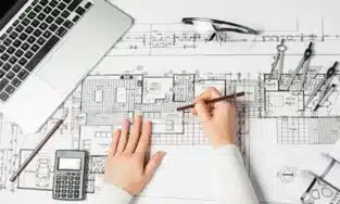

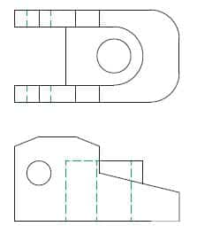
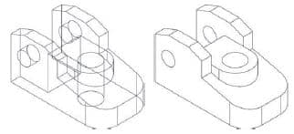

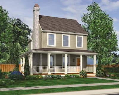 Computer-aided design and drafting (CADD) is the process of using a computer with CADD software for design and drafting applications. Software is the program or instructions that enable a computer to perform specific functions to accomplish a task. CADD refers to the entire range of design and drafting with the aid of a computer, from drawing basic 2-D objects to preparing complex 3-D models and animations. CAD is the acronym for computer-aided design and a common reference to computer-aided drafting. Computer-aided design and computer-aided drafting refer to specific aspects of the CADD process.