1800 287 223 · [email protected]
Step-by-step tutorial for creating your first CAD drawing in AutoCAD — engineering workstation, Australia

Learning how to create your first CAD Drawing can feel overwhelming at first, but once you understand the process, it becomes an exciting and rewarding skill. Whether you’re an aspiring engineer, architect, designer, or student, mastering computer-aided design (CAD) gives you the ability to bring ideas to life with precision and creativity.

In this beginner-friendly tutorial, we’ll guide you step-by-step through the process of creating your first CAD Drawing, from setting up your software to finalising your design for presentation or printing.


What is a CAD Drawing?

A CAD Drawing is a digital representation of an object, building, or mechanical part created using Computer-Aided Design (CAD) software. Unlike hand drafting, CAD drawings are accurate, easy to modify, and can be stored or shared digitally.

They’re widely used in industries such as:

  • Architecture: for floor plans and structural layouts
  • Mechanical Engineering: for parts, assemblies, and tools
  • Electrical Design: for wiring diagrams and circuit layouts
  • Civil Engineering: for roads, bridges, and land development plans

Step-by-Step Tutorial: How to Create Your First CAD Drawing

Step 1: Choose the Right CAD Software

The first step in your CAD journey is choosing a suitable program. Popular CAD software options include:

  • AutoCAD – great for 2D and 3D drafting
  • SolidWorks – ideal for mechanical part design
  • Fusion 360 – user-friendly for beginners and hobbyists
  • DraftSight or FreeCAD – perfect for those starting out on a budget

For beginners, AutoCAD or Fusion 360 are often the best starting points due to their tutorials and large online communities.


Step 2: Set Up Your Drawing Environment

Once you open your CAD software, set up your workspace.

  • Define units: Decide whether you’ll use millimetres, centimetres, or inches depending on your project.
  • Set limits: This defines the drawing area or boundary of your design.
  • Adjust grid and snap settings: The grid helps you align and control precision in your CAD Drawing.

These small setup steps ensure your design remains accurate and consistent.


Step 3: Create Basic Geometry

Now it’s time to start drawing!
Use simple shapes like lines, circles, rectangles, and arcs to build your base design.

For example:

  • Type LINE or click the line tool to draw straight lines.
  • Use CIRCLE or ARC to draw curves or round edges.
  • Use OFFSET or TRIM to fine-tune the shapes.

Each CAD command helps you create geometry faster and more precisely than traditional hand drafting.


Step 4: Use Layers to Organise Your Drawing

Layers are a vital feature in CAD software. Think of them as transparent sheets stacked on top of each other — each one containing a different part of your drawing.

For example:

  • Layer 1: Walls
  • Layer 2: Dimensions
  • Layer 3: Electrical Layout
  • Layer 4: Annotations

Using layers in your CAD Drawing helps you control visibility, colour, and line types — making your project more organised and professional.


Step 5: Add Dimensions and Annotations

A drawing is incomplete without measurements.
Use the Dimension tool to label distances, angles, and diameters.

Annotations can include:

  • Text labels (for part names or room numbers)
  • Notes (for special instructions)
  • Symbols (like arrows or welding marks)

Adding clear annotations ensures anyone reviewing your drawing understands the design intent without confusion.


Step 6: Apply Line Types and Thickness

Different line types represent different objects or functions:

  • Solid lines for visible edges
  • Dashed lines for hidden details
  • Center lines for symmetrical parts

Adjusting line weights and colours gives your CAD Drawing a professional appearance and makes it easier to interpret.


Step 7: Check and Clean Up Your Drawing

Before finalising, it’s important to check for:

  • Overlapping lines or gaps
  • Incorrect dimensions
  • Misaligned parts

Use tools like OVERKILL or AUDIT (in AutoCAD) to clean and verify your drawing. A clean, error-free file ensures accuracy and professionalism.


Step 8: Save, Print, or Export Your CAD Drawing

Finally, save your project in multiple formats:

  • .DWG or .DXF – Standard CAD formats for editing
  • .PDF – For sharing or printing
  • .STL or .STEP – For 3D modelling or manufacturing

Always save multiple backups of your work to prevent data loss. Once done, you can print your CAD Drawing or share it with clients, teachers, or collaborators.


Pro Tips for Beginners in CAD Drawing

  • Learn shortcuts: Commands like L (Line), C (Circle), M (Move), and TR (Trim) save time.
  • Use templates: Predefined templates speed up setup and ensure standardisation.
  • Practice regularly: The more you practice, the faster you’ll master CAD tools.
  • Watch tutorials: YouTube and online courses offer visual guidance for beginners.
  • Start simple: Begin with basic shapes before moving on to complex designs.

Conclusion

Creating your first CAD Drawing is an exciting milestone for any beginner. With the right software, organised workflow, and consistent practice, you can transform your ideas into precise digital blueprints.

Whether you’re designing a simple part or a complex architectural layout, CAD technology opens the door to endless design possibilities. So, fire up your CAD software, follow these steps, and start drafting your very first creation today!

What is CAD drafting — AutoCAD technical drawings and blueprints on engineering workstation in Australia

CAD drafting — short for Computer-Aided Design drafting — is the process of creating precise, detailed technical drawings using specialised software. It is the universal language of engineering and construction in Australia, replacing hand drafting from the 1980s onwards and becoming the foundation of every project from residential renovations through to major infrastructure. Whether you’re an engineer, project manager, architect, or builder, understanding what CAD drafting is and how it works helps you communicate more effectively with your drafting team and make better decisions for your project.

This guide covers the definition of CAD drafting, the different types, the software used, the key disciplines it covers in Australia, and why businesses choose to outsource it. If you’re looking for professional CAD drafting services across Brisbane, Sydney, Melbourne, Perth, or Gold Coast — or you’re simply trying to understand what your drafting provider actually does — you’re in the right place.


CAD drafting is the use of computer software to produce technical drawings — the precise, dimensioned, and standards-compliant documents that engineers, fabricators, builders, and councils use to construct or approve projects. It replaced traditional hand drafting (pencil on paper over a tilted drawing board) and is now the universal standard across all engineering and construction disciplines globally.

At its core, CAD drafting captures two things: geometry — the exact shape and dimensions of objects — and annotation — the notes, symbols, tolerances, and specifications that tell someone how to build it. A CAD drawing is not simply a picture. It is a precise technical document with legal and contractual significance, used to obtain council approvals, guide fabricators, and direct tradespeople on site.

In Australia, CAD drafting is governed by standards including AS1100 (Technical Drawing Standards) and the National Construction Code (NCC), which specify how drawings must be formatted, dimensioned, and labelled to be legally compliant and usable by contractors and councils.


Before CAD software, draftspeople worked at tilted drawing boards using pencils, rulers, set squares, and technical pens. Every line was drawn by hand, every revision required erasing and redrawing, and producing a full set of construction drawings could take weeks of skilled labour.

CAD software transformed this process completely. The key advantages over manual drafting are:

  • Speed: drawings that took days by hand can be completed in hours using CAD software.
  • Accuracy: dimensions are mathematically precise — there is no human measuring error in line placement or scaling.
  • Revisions: changing a design means editing the digital file, not starting over. Revisions that once took days now take minutes.
  • Reusability: components, drawing blocks, and standard details can be saved in libraries and reused across projects.
  • Collaboration: CAD files can be shared instantly with engineers, fabricators, builders, and councils anywhere in Australia or the world.
  • 3D capability: modern CAD software generates three-dimensional models that can be visualised, rotated, analysed, and simulated before a single piece of material is ordered.

CAD drafting encompasses a broad range of drawing types, outputs, and methodologies. Understanding the main categories helps you communicate clearly with your drafting provider and ensure you’re commissioning the right type of work for your project.

2D CAD drafting produces flat, plan-view drawings — floor plans, elevations, sections, construction details, schematics, and fabrication drawings. This is the most commonly requested output in construction and engineering. AutoCAD is the industry standard for 2D drafting and is used across mechanical, structural, electrical, architectural, and civil disciplines throughout Australia. 2D drawings are submitted for council approval, used on construction sites, and issued to fabricators for manufacturing.

3D CAD modelling creates three-dimensional digital representations of parts, assemblies, structures, or buildings. Software like SolidWorks, Inventor, and Fusion 360 are used for mechanical and product design, while Revit is used for architectural and structural 3D modelling. 3D models allow engineers to visualise designs before construction, run stress analyses and simulations, generate accurate material quantities, detect design clashes before they become costly site problems, and produce photorealistic renders for client approval.

BIM is an advanced form of 3D modelling that embeds data into the model — not just geometry, but specifications, costs, schedules, and performance data. A BIM model of a building contains information about every structural member, every pipe, every door — allowing project teams to coordinate design across all disciplines, detect clashes between structure, services, and architecture, and manage the asset through its entire lifecycle. Revit is the dominant BIM platform in Australia, and BIM is increasingly mandated on government infrastructure and commercial projects.

Schematic drafting is used in electrical engineering to produce single line diagrams, panel layouts, P&IDs (Piping and Instrumentation Diagrams), and wiring diagrams. Software like AutoCAD Electrical and EPLAN are used for these specialised outputs. Unlike plan drawings, schematics are not drawn to scale — they show logical connections and system relationships rather than physical geometry and placement.


CAD drafting is used across every engineering discipline in Australia. Each has its own standards, preferred software, and drawing conventions that drafters must understand deeply to produce compliant, usable documentation.

Mechanical CAD drafting covers machine components, assemblies, manufacturing drawings, fabrication details, sheet metal design, and product development. It requires deep knowledge of tolerancing (GD&T), material properties, and manufacturing processes. Software used includes AutoCAD, SolidWorks, and Inventor. ASTCAD’s mechanical drafting services serve mining, aerospace, marine, automotive, and industrial manufacturing clients across Australia.

Structural CAD drafting produces drawings for steel, concrete, and timber structures — including structural steel shop drawings, reinforcement drawings, connection details, and AS/NZS-compliant structural documentation. Structural drafting works alongside structural engineers and must comply with Australian standards including AS4100 (steel structures) and AS3600 (concrete structures). Explore our structural drafting services for more detail on what’s involved.

Electrical CAD drafting covers schematics, panel drawings, single line diagrams, wiring diagrams, and electrical layouts for commercial, industrial, and residential projects. Australian electrical drawings must comply with AS/NZS 3000 (the Wiring Rules) and relevant industry codes. Our electrical drafting team works with electricians, electrical engineers, and OEM manufacturers across Brisbane, Sydney, Melbourne, and Perth.

Architectural CAD drafting produces floor plans, elevations, sections, 3D renders, development application (DA) drawings, and construction documentation for residential, commercial, and industrial buildings. In Australia, architectural drawings submitted for council approval must meet specific formatting and content requirements under the NCC and each council’s local planning scheme. Accuracy and compliance at DA stage can save months of back-and-forth with local authorities.

Civil CAD drafting covers roads, drainage, stormwater, sewerage, earthworks, and site development drawings. Civil drafters typically use AutoCAD Civil 3D and must produce documentation compliant with local council infrastructure standards and the AGRD (Australian Guide to Road Design). Our civil drafting services support land developers, civil engineers, and local governments across Australia.


The software used depends on the discipline and type of output required. Here are the most commonly used CAD platforms in Australian engineering and construction in 2026:

  • AutoCAD: the universal industry standard for 2D drafting across all disciplines — used by the vast majority of Australian drafters.
  • Revit: the dominant BIM platform for architectural, structural, and MEP (mechanical, electrical, plumbing) design in Australia.
  • SolidWorks: the leading software for mechanical product design, assemblies, and manufacturing drawings.
  • Inventor: Autodesk’s mechanical CAD and product simulation platform, widely used in Australian manufacturing and industrial design.
  • Civil 3D: Autodesk’s civil engineering platform for road design, drainage, earthworks, and land development.
  • MicroStation / OpenRoads: used primarily on major infrastructure and government projects in Australia, particularly for transport and utilities.
  • Navisworks: used for BIM model coordination, multi-discipline clash detection, and 4D construction simulation.

Many engineering firms, builders, and manufacturers outsource their CAD drafting to specialist companies rather than employing full-time in-house drafters. The reasons are straightforward:

  • Cost efficiency: outsourcing avoids the full cost of employment — superannuation, leave entitlements, equipment, ongoing training, and office space are all transferred to the provider.
  • Scalability: project workloads fluctuate. Outsourcing lets you scale drafting resources up or down without the complexity and cost of hiring or making staff redundant.
  • Access to specialists: a full-service CAD company has mechanical, structural, electrical, architectural, and civil drafters — giving you access to every discipline without maintaining separate specialist employees.
  • Turnaround speed: established CAD companies have proven workflows, drawing templates, and block libraries that allow faster delivery than building that capability in-house from scratch.
  • Software and licensing: professional CAD software licences are expensive and require ongoing maintenance. Outsourcing transfers that cost and responsibility to the provider.

CAD drafting is used to produce technical drawings for engineering, construction, and manufacturing projects. Common applications include architectural floor plans and council documentation, structural steel shop drawings, mechanical fabrication drawings, electrical schematics and panel layouts, civil engineering road and drainage plans, product design drawings for manufacturing, and 3D models for simulation, rendering, and 3D printing.

Drafting is the broader discipline of producing technical drawings — it existed long before computers, using pencil and paper on a drawing board. CAD (Computer-Aided Design) is the computer-based method of performing that same work. In modern professional practice in Australia, CAD drafting and drafting are effectively synonymous — virtually all technical drawing is now done using CAD software rather than by hand.

Engineers design — they determine what needs to be built, perform calculations, and take professional responsibility for the design. CAD drafters document — they translate the engineer’s design intent into precise, construction-ready drawings. Most projects need both. Many CAD companies (including ASTCAD) employ licensed engineers on staff who can provide both engineering design and drafting services under one roof, simplifying the project management process significantly.

CAD drawings are mathematically precise — dimensions in a CAD file are exact to whatever unit of measurement is used. Accuracy in a delivered drawing depends on the quality of the input information and the skill of the drafter. A CAD drafter working from a good brief, accurate survey data, and clear engineering input will produce drawings accurate to fractions of a millimetre. This precision is one of the primary advantages of CAD over manual drafting, which introduced human measurement error at every step.

The most common CAD file formats in Australia are DWG (AutoCAD’s native format and the universal industry standard), DXF (Drawing Exchange Format for cross-software compatibility), PDF (for distribution, review, and council submission), RVT (Revit’s native BIM format), and SLDPRT/SLDASM (SolidWorks part and assembly files). Always confirm what format your fabricator, contractor, or engineer requires before work commences — most CAD companies can deliver in multiple formats at no extra cost.

Look for a company with licensed engineers overseeing the work, demonstrated experience in your specific discipline, a clear familiarity with Australian Standards, and a transparent quoting and revision process. Ask to see samples of comparable work, confirm their software matches your project requirements, and check whether they have a local Australian presence — particularly important for projects requiring site visits, council liaison, or direct collaboration with your engineering team.


ASTCAD is a Brisbane-based CAD design and drafting company serving engineering firms, builders, manufacturers, and architects across Australia. With expertise across mechanical, structural, electrical, architectural, and civil disciplines, our team delivers accurate, standards-compliant drawings with a 24-hour quote turnaround. Get your free quote today.

What is CAD drafting used for?

CAD drafting is used to produce precise technical drawings for engineering, construction, and manufacturing projects across Australia. We create architectural floor plans, structural shop drawings, mechanical fabrication drawings, electrical schematics, and civil engineering plans that meet Australian Standards and building codes. Our CAD services help engineers, architects, and contractors visualize projects, streamline construction processes, and ensure compliance with local regulations before work begins on site.

What is the difference between CAD and drafting?

Drafting is the discipline of creating technical drawings that communicate design intent, while CAD is the computer technology that enables this work. In Australia’s engineering and construction sectors, these terms are now virtually interchangeable since almost all professional drafting relies on CAD software like AutoCAD or Revit. We use CAD tools to produce drawings that comply with Australian Standards and support building approvals, ensuring precision and efficiency that manual drafting simply cannot match.

Do I need a CAD drafter or an engineer?

Engineers design and take professional responsibility for the design, while CAD drafters translate that vision into precise, construction-ready drawings. Most Australian projects require both roles working together. We recommend consulting an engineer for complex structural or compliance work, then having a CAD drafter prepare detailed drawings for builders and council submissions. ASTCAD has licensed engineers on staff who can provide both services, ensuring your project meets Australian building codes and standards from concept through construction documentation.

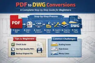
PDF To DWG Conversions

In today’s design and engineering workflows, drawings are often shared in PDF format because it’s easy to view, print, and distribute. However, when you need to edit, modify, or reuse drawings, PDFs quickly become a limitation. This is where PDF to DWG conversions play a crucial role.

Whether you’re an architect, engineer, contractor, or CAD beginner, understanding how to convert PDF files into editable DWG format can save time, reduce rework, and improve accuracy. This beginner-friendly guide walks you through the entire PDF to DWG conversion process, tools, challenges, and best practices.


What is PDF to DWG conversion?

PDF to DWG conversion is the process of transforming a PDF drawing into a DWG file, which is the native format used by AutoCAD and other CAD software. Once converted, the drawing becomes fully editable, allowing users to modify dimensions and layouts, edit layers and annotations, reuse existing designs, and extract accurate CAD data.

PDF to DWG conversions are commonly used for legacy drawings, as-built plans, and scanned documents.


Why PDF to DWG conversion is important

  • Editable drawings: Convert static PDFs into fully editable CAD files
  • Cost efficiency: Avoid redrawing from scratch
  • Accuracy improvement: Maintain scale and geometry
  • Better collaboration: DWG files are easier to share and revise
  • Time saving: Faster updates and revisions

Types of PDFs used for conversion

1. Vector-based PDFs

Created directly from CAD software, vector PDFs contain actual lines, arcs, and text objects. These are far easier and more accurate to convert — the geometry is already defined mathematically, so conversion tools can extract it cleanly.

2. Raster-based (scanned) PDFs

Created by scanning paper drawings, raster PDFs are essentially images. They require additional cleanup and tracing after conversion. Quality depends heavily on scan resolution — a 300 DPI scan will convert significantly better than a faded 72 DPI photocopy.


Step-by-step guide: PDF to DWG conversion for beginners

Step 1: Review the PDF file

Check drawing scale and clarity, identify layers, text, and dimensions, and determine whether the source is a scanned or vector-based PDF. This determines your tool choice and how much manual cleanup to expect.

Step 2: Choose the right conversion tool

Common options include AutoCAD’s built-in PDF import (PDFIMPORT command), online PDF to DWG converters, dedicated CAD conversion software, and professional conversion services. For beginners, AutoCAD’s built-in tools are a reliable starting point for vector PDFs.

Step 3: Import or convert the PDF

Open AutoCAD, use the PDFIMPORT command, select your PDF file, choose the relevant pages, and adjust import settings. For scanned PDFs, you’ll need a raster-to-vector tracing step first.

Step 4: Check scaling and units

Verify drawing units (mm, inches, metres) and use known reference dimensions to confirm the scale is correct before editing anything. Scaling errors caught early save significant rework later.

Step 5: Organise layers

Separate walls, dimensions, text, and symbols into named layers. Delete unnecessary elements. A well-layered DWG is far easier to work with and is expected by most engineering and architecture clients.

Step 6: Clean and edit the drawing

Remove duplicate lines, fix broken geometry, align misinterpreted elements, and convert exploded text back into editable text objects. This is the most time-consuming step for raster-source conversions.

Step 7: Final quality check

Verify dimensions against the original PDF, check alignment and accuracy, and save in the required DWG version for your client or project requirements.


Common challenges in PDF to DWG conversions

  • Incorrect scaling after import
  • Text converted as polylines instead of editable text
  • Extra or broken lines from PDF compression artefacts
  • Missing or incorrectly mapped layers
  • Poor quality scanned PDFs producing unusable geometry

Best PDF to DWG conversion tips

  • Always verify scale after conversion using a known dimension
  • Use high-resolution PDFs (300 DPI minimum for scanned drawings)
  • Clean the drawing before starting new edits
  • Don’t over-trust auto-conversion tools — always manually review critical dimensions
  • Keep a backup of the original PDF before making any edits

What is the best software for PDF to DWG conversion?

At ASTCAD, we recommend AutoCAD’s built-in PDF import for straightforward conversions, though it works best with simpler drawings. For more complex Australian construction or engineering projects involving multiple layers or precise specifications, we suggest dedicated conversion software or our professional conversion services. We’ve found that outsourcing to specialists like us ensures accuracy with local building standards and compliance requirements, saving you time and potential rework costs.

Can scanned PDFs be converted to DWG?

Yes, we can convert scanned PDFs to DWG, though the process requires additional work since scanned files are raster-based images rather than vector data. The accuracy of your conversion depends heavily on the original scan quality, and you’ll typically need to perform manual editing and cleanup to ensure the DWG file meets Australian building standards and complies with relevant engineering specifications. We recommend starting with high-resolution scans and allowing extra time for vectorization if precision is critical for your project.

Is PDF to DWG conversion 100% accurate?

No automatic conversion is 100% accurate, and we always recommend manual verification and editing to ensure precision. PDF files often contain embedded fonts, complex layering, or compressed data that don’t translate perfectly to DWG format, particularly with technical drawings common in Australian construction and engineering standards. We suggest reviewing converted files carefully and adjusting line weights, layers, and dimensions to meet your project requirements. Our team can assist with quality checking if needed.

How long does a PDF to DWG conversion take?

The conversion time depends on your file’s complexity and type. Simple vector PDFs typically convert in minutes, while complex drawings or scanned documents may take several hours. At ASTCAD, we recommend uploading your files during business hours so our team can prioritise them if needed. For urgent projects, contact us directly to discuss expedited processing options that suit Australian construction and engineering timelines.

Are online PDF to DWG converters safe to use?

We recommend caution with online PDF to DWG converters, especially for confidential architectural or engineering projects. While free online tools work for basic drawings, we advise using trusted desktop software or our professional conversion services for sensitive files containing intellectual property or client details. Australian firms handling building plans or technical drawings should prioritise data security and quality accuracy, which our specialist team can guarantee through secure, local processing.

What file version should I save the DWG in?

We recommend saving your DWG in AutoCAD 2010 or later versions, as these are widely supported across Australian design practices and construction teams. Check with your clients or consultants first, as some projects specify particular versions for compatibility. If you’re unsure, AutoCAD 2018 format offers excellent compatibility with most Australian firms while maintaining good file stability. Our team can assist if you need guidance on version selection for your specific project requirements.

Also useful: CAD Drawing — Complete Guide for Australian Engineers and Drafters | Fabrication Shop Drawing Checklist


CS

Claire Sutton

Architectural CAD Specialist & Technical Writer · BArch (Hons), QUT · ASTCAD, Brisbane

Claire has 10 years of experience in Revit BIM modelling, architectural documentation, and CAD conversion projects across Southeast Queensland and NSW. She has delivered NCC-compliant documentation for residential, commercial, and industrial facilities.

More articles by Claire Sutton →
DWG to DGN Conversion

In today’s collaborative engineering and infrastructure projects, working with multiple CAD file formats is common. Two of the most widely used formats are DWG (AutoCAD) and DGN (MicroStation). When teams use different software platforms, accurate file conversion becomes essential. This is where DWG to DGN conversion plays a critical role.

This beginner-friendly guide explains everything you need to know about DWG to DGN conversion, including tools, processes, best practices, and common challenges.

What is DWG to DGN conversion?

DWG to DGN conversion is the process of transforming AutoCAD DWG files into MicroStation DGN format while maintaining design accuracy, layers, annotations, and geometry. DWG is primarily used in AutoCAD and other Autodesk tools, while DGN is the native format of Bentley MicroStation, widely used in infrastructure, transportation, and civil engineering projects.

Why DWG to DGN conversion is important

  • Cross-platform project collaboration
  • Government and infrastructure projects requiring DGN files
  • Maintaining design consistency across CAD software
  • Reducing rework and manual redrawing
  • Improving workflow efficiency

Common challenges

  • Loss of layers or incorrect layer mapping
  • Font and text alignment issues
  • Line style and weight mismatches
  • Missing blocks or symbols
  • Scaling and unit inconsistencies

Step-by-step guide

Step 1: Review the DWG file

Clean unnecessary layers, remove unused blocks and references, check drawing units and scale, and ensure text styles and fonts are standard.

Step 2: Choose the right conversion tool

Options include Bentley MicroStation, AutoCAD with export options, or dedicated CAD conversion software.

Step 3: Set conversion preferences

Map DWG layers to DGN levels, define line styles and weights, match colours and symbology, and set correct units and scale.

Step 4: Convert DWG to DGN

Import or open the DWG file in MicroStation, save or export in DGN format, and use batch conversion for multiple files if needed.

Step 5: Verify the converted DGN file

Check geometry accuracy, review text, dimensions and annotations, verify layers and line styles, and confirm scale and alignment.

Step 6: Final cleanup and optimisation

Fix text spacing issues, correct level naming, optimise file size, and apply MicroStation standards if required.

Best conversion tips

  • Always clean DWG files before conversion
  • Use standard fonts to avoid text errors
  • Maintain consistent units across files
  • Test convert a sample file before batch processing
  • Perform post-conversion quality checks

What is the difference between DWG and DGN files?

DWG and DGN are two distinct file formats used across the Australian engineering and construction industry. DWG, developed by Autodesk for AutoCAD, is the most widely used format in Australia and stores design data in a proprietary structure. DGN, used by Bentley’s MicroStation, is common in infrastructure and civil projects. The key differences lie in how they handle layers, symbology, and coordinate systems—DWG uses a flatter structure while DGN supports more complex cell-based elements, which can affect how our team converts between them for Australian projects.

Can DWG be converted to DGN without data loss?

Yes, with proper tools and settings, DWG to DGN conversion can be done with minimal or no data loss. Here at ASTCAD, we use specialised conversion software that preserves layer structures, line weights, and annotation data that comply with Australian standards. We recommend pre-conversion checks to ensure all custom blocks and references are compatible with MicroStation environments commonly used by Australian engineering firms. Our team can guide you through the process to maintain data integrity throughout the conversion.

Which software is best for DWG to DGN conversion?

Bentley MicroStation is one of the most reliable tools for accurate DWG to DGN conversion, and we recommend it as the industry standard for Australian engineering and infrastructure projects. We’ve successfully converted thousands of drawings for clients across Australia, and MicroStation consistently delivers high-fidelity conversions while preserving complex layer structures and annotation details. For best results, we suggest using MicroStation’s native conversion features rather than third-party tools, as this maintains compatibility with Australian standards and ensures your infrastructure designs remain precise throughout the conversion process.

Are DWG to DGN conversion tutorials helpful for beginners?

Yes, step-by-step tutorials help beginners understand settings, avoid errors, and ensure accurate results.

What are the most common DWG to DGN conversion errors?

The most common DWG to DGN conversion errors we see include incorrect layer mapping, font substitution issues, scale mismatches particularly with Australian standard drawing sizes, and line style differences between formats. We recommend validating your layer structures before conversion and ensuring all custom fonts are embedded or substituted with standard alternatives. Our team always advises checking scale settings against Australian engineering standards to prevent costly revisions on site.

Should I convert DWG to DGN manually or use professional services?

For simple drawings, manual conversion is sufficient. For complex or large projects, professional services are recommended.


CS

Claire Sutton

Architectural CAD Specialist & Technical Writer · BArch (Hons), QUT · ASTCAD, Brisbane

Claire has 10 years of experience in Revit BIM modelling, architectural documentation, and CAD conversion projects across Southeast Queensland and NSW. She has delivered NCC-compliant documentation for residential, commercial, and industrial facilities.

More articles by Claire Sutton →
CAD Automation

In today’s fast-paced engineering and construction environment, efficiency and accuracy are no longer optional—they are essential. This is where CAD automation plays a critical role. By automating repetitive drafting and design tasks, organisations can significantly reduce errors, improve productivity, and ensure consistency across projects.

What is CAD automation?

CAD automation refers to the use of scripts, macros, rule-based systems, and software integrations to automate repetitive and time-consuming CAD tasks. By following structured CAD automation tutorials, teams can standardise workflows, reduce manual intervention, and achieve faster project turnaround times.

Benefits of CAD automation

  • Increased productivity by reducing repetitive manual tasks
  • Improved accuracy through standardised rules and templates
  • Faster project delivery with automated drafting workflows
  • Cost savings due to reduced rework and errors
  • Consistency across drawings regardless of project scale

Step 1: Identify repetitive tasks for automation

Common automation candidates include title block updates, layer creation and naming, dimensioning and annotation, block and symbol placement, file formatting and plotting, and BOM extraction.

Review completed projects and consult your CAD team to identify processes that consume excessive time. This step is critical in all CAD automation tutorials.

Step 2: Choose the right CAD automation tools

  • AutoLISP for AutoCAD
  • VBA and .NET APIs for advanced automation
  • Scripts and macros for repetitive commands
  • Parametric modelling tools
  • Third-party CAD automation plugins

Step 3: Standardise CAD templates and libraries

Automation works best when your drawings follow consistent standards. Standardise drawing templates, layer naming conventions, dimension styles, text styles, and block libraries before writing any scripts or macros.

Step 4: Develop simple automation scripts

Start small with scripts that automate basic tasks such as layer creation or title block updates. Examples: automatically generate layers based on project type, insert standard blocks with predefined attributes, or batch rename drawing files.

Step 5: Test automation on sample projects

Always test automation on sample files before deploying across live projects. Verify drawing accuracy, check compliance with standards, ensure compatibility with existing files, and confirm output consistency.

Step 6: Train your team

Training should include how to run scripts and macros, understanding automation limitations, basic troubleshooting, and best practices for automation use. Encouraging feedback from users will help refine your automation system over time.

Step 7: Integrate with other systems

  • CAD + ERP systems
  • CAD + BIM platforms
  • CAD + spreadsheet tools
  • CAD + document management systems

Step 8: Monitor, optimise, and scale

CAD automation is not a one-time task. Regularly monitor performance, improve scripts based on user feedback, expand automation to new workflows, and document all automation processes.

Implementing CAD automation is a smart investment for organisations looking to improve productivity, accuracy, and consistency. Contact ASTCAD to learn how our CAD automation services can streamline your drafting workflow.

What are CAD automation tutorials used for?

CAD automation tutorials help you streamline repetitive drafting tasks using scripts, macros, and built-in tools, which is essential for Australian firms managing large-scale projects across construction, engineering, and surveying sectors. Our tutorials guide you through automating common workflows like layer management, dimensioning, and compliance with Australian standards, ultimately reducing manual errors and freeing your team to focus on complex design work. We’ve found that implementing automation can significantly accelerate project timelines while maintaining the precision required for local council approvals and building code compliance.

Is CAD automation suitable for small projects?

Yes, CAD automation is beneficial for all project sizes, including small ones. We find that even basic automation routines can significantly reduce manual drafting time and minimise errors in your designs. For smaller Australian projects, you might start with simple tasks like standardising your line weights to comply with AS/NZS standards or automating common detail blocks. This approach lets you experience productivity gains without major workflow disruption, making it an ideal entry point before expanding automation across larger projects.

Do I need programming skills for CAD automation?

No, you don’t need programming skills to get started with CAD automation. We offer user-friendly tools and templates that allow Australian drafters and engineers to automate common tasks like layer management, title block updates, and repetitive drawing commands without any coding. For more advanced automation tailored to your specific workflows, our team can help you implement custom scripts, or you can develop basic automations using our intuitive interface. Most of our clients find that standard automation features save significant time on typical Australian building and construction projects right away.

What are the best CAD automation tips for beginners?

We recommend starting with simple repetitive tasks like generating standard title blocks or border sheets using our local Australian templates that comply with AS/NZS standards. Standardize your drawing conventions across your team first, then gradually introduce automation tools through our platform’s built-in features. Test all automated processes thoroughly in a controlled environment before rolling out to live projects, and invest time in training your team so they understand how to maintain and modify automation workflows. This staged approach helps Australian practices avoid disruptions while building confidence with CAD automation capabilities.

Can CAD automation reduce project costs?

Yes, CAD automation can significantly reduce your project costs. By minimizing design errors and rework, our automation solutions help Australian drafting teams work more efficiently, which directly lowers labour expenses and project timelines. We’ve helped many local engineering firms streamline their workflows, reduce manual drafting tasks, and deliver projects faster while maintaining quality standards. This means better margins for your business and faster turnaround for your clients.


JH

James Hartley

Senior Mechanical Engineer · BEng (Mechanical), UQ · Member, Engineers Australia · ASTCAD, Brisbane

James has 14 years of hands-on experience delivering CAD design, structural drafting, and engineering documentation across Australia’s mining, oil & gas, and manufacturing sectors. He specialises in SolidWorks, Autodesk Inventor, and AutoCAD for complex multi-discipline projects.

More articles by James Hartley →
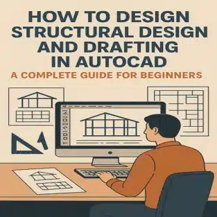
Structural Detailing

Structural detailing plays a vital role in transforming structural concepts into buildable, accurate, and safe construction documents. For beginners entering the field of structural engineering or CAD drafting, understanding the fundamentals of structural detailing is essential for producing high-quality drawings that meet industry standards. This Beginner’s Guide to Structural Detailing in Design and Drafting explains the core principles, workflows, and best practices that every novice should master.

What Is Structural Detailing in Design and Drafting?

Structural detailing is the process of preparing detailed drawings that show how structural elements such as beams, columns, slabs, footings, and reinforcements are to be constructed and assembled. These drawings act as a communication bridge between structural engineers, architects, contractors, and fabricators.

In structural design and drafting, detailing ensures that the engineer’s calculations are correctly represented on drawings, allowing structures to be built safely, efficiently, and without confusion on-site.


Importance of Structural Detailing for Beginners

For beginners, structural detailing is more than just drafting lines—it is about accuracy, coordination, and constructability. Poor detailing can lead to site errors, material wastage, delays, and safety risks.

Learning proper structural design and drafting tips early helps beginners:

  • Understand real-world construction practices
  • Improve drawing clarity and accuracy
  • Reduce rework and revisions
  • Build strong foundations for advanced structural projects

Key Structural Elements Every Beginner Should Know

Before starting structural detailing, beginners must be familiar with common structural components:

1. Foundations

Foundation drawings include footings, piles, pile caps, and raft foundations. Details must clearly show dimensions, reinforcement layouts, levels, and concrete grades.

2. Columns

Column detailing includes size, reinforcement bars, ties, lap lengths, and connection points with beams and slabs.

3. Beams

Beam details specify width, depth, reinforcement arrangement, stirrup spacing, and support conditions.

4. Slabs

Slab detailing shows thickness, reinforcement direction, spacing, openings, and edge conditions.

Understanding these components is essential in structural design and drafting tutorials for beginners.


Structural Design and Drafting Tips for Beginners

Here are some practical tips to help beginners create accurate and professional structural detailing drawings:

1. Start with Clear Design Intent

Always review architectural and structural design drawings before detailing. Understand load paths, structural systems, and material requirements.

2. Follow Drafting Standards

Use standard symbols, line types, fonts, and dimensioning styles as per local and international codes. Consistency improves readability.

3. Maintain Proper Scaling

Use appropriate scales for plans, sections, and details. Overcrowded drawings can confuse contractors.

4. Use Layers Effectively

Organise drawings using layers for beams, columns, reinforcement, dimensions, and annotations. This is a key structural design and drafting tip for managing complex drawings.

5. Add Clear Notes and Callouts

Well-written notes reduce ambiguity. Always specify material grades, bar diameters, spacing, and construction instructions.


Structural Design and Drafting Tutorials: Step-by-Step Workflow

Beginners can follow this basic workflow when learning structural detailing:

Step 1: Review Design Inputs
Study structural calculations, architectural plans, and design notes.

Step 2: Set Up the Drawing Template
Prepare CAD templates with proper units, scales, title blocks, and layers.

Step 3: Create Structural Layouts
Draft column grids, beam layouts, slab outlines, and foundation plans.

Step 4: Add Detailed Sections and Elevations
Include cross-sections, reinforcement details, and connection drawings.

Step 5: Perform Quality Checks
Check dimensions, reinforcement continuity, clash issues, and compliance with codes.

These structural design and drafting tutorials help beginners follow a systematic and error-free approach.


Common Mistakes Beginners Should Avoid

Many beginners struggle with similar detailing errors. Avoid these common mistakes:

  • Missing reinforcement details
  • Incorrect dimensions or scales
  • Overlapping text and symbols
  • Lack of coordination with architectural drawings
  • Ignoring construction feasibility

Learning from these mistakes improves drafting confidence and efficiency.


Tools Used for Structural Detailing

Beginners commonly use the following tools:

  • AutoCAD for 2D structural drafting
  • Revit Structure for BIM-based detailing
  • Excel for bar bending schedules
  • PDF markup tools for revisions

Mastering these tools supports long-term growth in structural design and drafting.


Benefits of Good Structural Detailing

Accurate structural detailing provides:

  • Smooth construction execution
  • Reduced site queries and RFIs
  • Improved safety and compliance
  • Cost and time savings
  • Better coordination among project teams

For beginners, developing strong detailing skills opens doors to professional drafting and engineering roles.


Final Thoughts

Structural detailing is a critical skill in the construction and engineering industry. For beginners, learning the fundamentals through structured practice, clear standards, and hands-on structural design and drafting tutorials can significantly improve drawing quality and career growth. By following proven structural design and drafting tips, beginners can confidently create accurate, buildable, and professional structural drawings.

What is the difference between structural design and structural detailing?

Structural design focuses on calculations and analysis to determine how a building will perform, while structural detailing converts those designs into clear, constructable drawings that builders can follow. We at ASTCAD understand that detailing requires knowledge of Australian Standards, construction methods, and site-specific requirements. Our experienced drafters ensure every dimension, material specification, and connection detail is precise and compliant with local building codes, making your project ready for construction.

Is structural detailing difficult for beginners?

It can be challenging initially, but with proper tutorials, practice, and drafting standards, beginners can master it effectively.

Which software is best for beginners in structural detailing?

At ASTCAD, we recommend AutoCAD for beginners starting their structural detailing journey, as it offers an intuitive interface and is widely used across Australian construction projects. For those interested in Building Information Modelling, Revit provides excellent capabilities for coordinating structural elements with other disciplines. We’ve found that many Australian engineers and drafters benefit from learning AutoCAD first to master fundamental detailing principles, then progressing to Revit for more complex, multi-disciplinary projects. Both software options align well with Australian building codes and standards.

Why are structural detailing drawings important?

Structural detailing drawings are crucial because they ensure accurate construction, reduce costly errors, and help contractors clearly understand reinforcement placement and assembly requirements. At ASTCAD, we create detailed drawings that comply with Australian Standards and building codes, providing contractors with the precise specifications needed for safe and efficient on-site execution. Our comprehensive details save time and money by preventing misinterpretation and rework during construction.

How long does it take to learn structural detailing?

With consistent practice, beginners can learn basic structural detailing within 3–6 months. At ASTCAD, we recommend starting with Australian Standards like AS 3600 for concrete and AS 4100 for steel, which form the foundation of our local drafting practices. Our experience shows that mastering these standards alongside CAD software typically takes 6–12 months for proficiency. The timeline varies depending on your prior experience with design software and engineering concepts, but we’re here to guide you through every stage of your learning journey.

What are the essential skills needed for structural drafting?

Understanding construction methods, drafting standards, CAD tools, and structural fundamentals are key skills.


JH

James Hartley

Senior Mechanical Engineer · BEng (Mechanical), UQ · Member, Engineers Australia · ASTCAD, Brisbane

James has 14 years of hands-on experience delivering CAD design, structural drafting, and engineering documentation across Australia’s mining, oil & gas, and manufacturing sectors. He specialises in SolidWorks, Autodesk Inventor, and AutoCAD for complex multi-discipline projects.

More articles by James Hartley →

Need expert structural design services in Australia? ASTCAD’s structural design team delivers compliant engineering drawings and documentation for residential, commercial and industrial projects across Brisbane, Sydney, Melbourne and Perth. Request a free quote today.

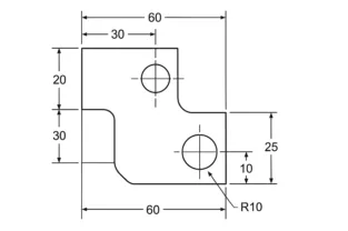
2D Mechanical Drawing

Learning how to create your first 2D Mechanical Drawing in AutoCAD can feel challenging at first, but once you understand the basic tools and workflow, the entire drafting process becomes smooth and enjoyable. AutoCAD is one of the most widely used CAD software in the mechanical engineering industry because of its precision, flexibility, and powerful drafting capabilities. Whether you are a student, beginner, or aspiring mechanical drafter, this step-by-step guide will help you confidently create accurate and professional 2D drawings.

2D Mechanical Drawing in AutoCAD

In this tutorial, we’ll walk through the essential stages of setting up your workspace, creating geometry, adding dimensions, and preparing your final drawing for printing or sharing. By the end, you’ll have a clear understanding of how to draft your first 2D Mechanical Drawing in AutoCAD from scratch.

1. Start by Setting Up Your AutoCAD Workspace

Before creating any drawing, it’s essential to set up your workspace for mechanical drafting. This includes choosing measurement units, limits, layers, and important drafting settings.

Steps:

  • Open AutoCAD and start a new drawing.
  • Type UNITS → set to Millimetres (or Inches) depending on the project.
  • Set the precision to a suitable value (typically 0.00 for mechanical drawings).
  • Use the LIMITS command to define your working area.
  • Type Z → A to zoom all.

A well-configured workspace ensures consistency and accuracy throughout your 2D Mechanical Drawing in AutoCAD.

2. Create Layers for Better Organisation

Layers help you organise your drawing by separating objects like outlines, hidden lines, centerlines, hatching, and dimensions.

Suggested Layers:

  • Object (Continuous Line, 0.50 mm)
  • Centerline (Center Linetype)
  • Hidden (Hidden Linetype)
  • Dimension (Continuous, lighter colour)
  • Hatch (Solid or pattern)

Use LAYER command → create these layers → assign colours and linetypes.
Always draw mechanical components on the correct layer for a neat and professional finish.

3. Start Creating Basic Shapes Using Drawing Tools

Mechanical drawings often begin with simple shapes—circles, lines, arcs, and rectangles—that later combine into complete machine components.

Important Tools to Use:

  • LINE
  • CIRCLE
  • ARC
  • RECTANGLE
  • POLYLINE

Example Steps:

  1. Draw the main body using the LINE or POLYLINE tool.
  2. Add circular holes using CIRCLE.
  3. Create fillets using the FILLET command.
  4. Use OFFSET to create parallel edges or features.
  5. Use TRIM and EXTEND to refine geometry.

Break the part down into simple features and draft them step-by-step. This method helps beginners build the entire 2D Mechanical Drawing in AutoCAD easily.

4. Add Centerlines and Hidden Lines

Mechanical drawings require proper representation of hidden edges and center points.

Add Centerlines:

  • Draw lines along the symmetry or center axis.
  • Use Center linetype for correct representation.

Add Hidden Lines:

  • Use dashed/hidden linetype to indicate features not visible from the viewing direction.
  • Ensure hidden lines do not overpower object lines.

These elements make your 2D Mechanical Drawing in AutoCAD follow industry drafting standards.

5. Use AutoCAD Modify Tools for Precision

Modify tools help refine your sketch to match exact mechanical dimensions.

Common Tools:

  • TRIM
  • EXTEND
  • FILLET
  • MIRROR
  • MOVE
  • COPY
  • OFFSET

For symmetrical parts, the MIRROR tool saves time and ensures perfect alignment.
For repeated features, use ARRAY command to create patterns like holes or slots.

6. Add Accurate Dimensions to Your Mechanical Drawing

Dimensioning is one of the most important parts of mechanical drafting. AutoCAD provides multiple dimensioning tools to capture sizes, distances, and angles.

Add Dimensions Using:

  • DIMLINEAR for straight edges
  • DIMDIAMETER for hole diameters
  • DIMRADIUS for arcs
  • DIMALIGNED for slanted edges
  • DIMCENTER for center marks
  • DIMANGULAR for angles

Make sure to:

  • Use consistent dimension text height (2.5 mm or as per standard).
  • Avoid overlapping or cluttered dimensions.
  • Follow standard dimensioning rules (ISO/ANSI).

Good dimensioning ensures the manufacturer can understand your 2D Mechanical Drawing in AutoCAD without confusion.

7. Apply Hatching for Section Views (Optional)

If your drawing includes a section view, add hatching to show material cut areas.

Steps:

  • Use HATCH command.
  • Choose appropriate pattern (ANSI31 is common for mechanical parts).
  • Select the area to apply hatch.
  • Adjust scale to match drawing size.

Hatching helps make your drawing more readable and professional.

8. Add Title Block and Border

A complete mechanical drawing includes a title block with essential information.

Include:

  • Part Name
  • Drawing Number
  • Material
  • Scale
  • Date
  • Drafter Name
  • Revision Table

Insert a pre-made title block or draw your own and place it in Layout Tab (Paper Space).

9. Prepare the Drawing for Printing (Plotting)

To finalise your 2D Mechanical Drawing in AutoCAD, set up plotting settings.

Steps:

  1. Switch to Layout View.
  2. Choose paper size (A4/A3/A2).
  3. Insert viewport and adjust scale (1:1, 1:2, 2:1 or as needed).
  4. Use PLOT command.
  5. Choose plot style monochrome.ctb for clean black & white output.

Your drawing is now ready for professional use.

Is AutoCAD good for beginners learning mechanical drafting?

Yes, AutoCAD is excellent for beginners learning mechanical drafting. We recommend it because its intuitive commands are easy to master, and it’s the industry standard used across Australian engineering firms and manufacturers. You’ll gain skills that are highly valued in the local job market, and our tutorial guides you through creating professional drawings that meet Australian Standards.

How long does it take to learn 2D Mechanical Drawing in AutoCAD?

Most beginners can start creating simple 2D mechanical drawings within 1–2 weeks of practice with AutoCAD. At ASTCAD, we recommend dedicating 2–3 hours daily to tutorials and hands-on projects to build confidence with essential tools like line, circle, and dimension commands. Proficiency with Australian drafting standards and technical conventions typically takes 4–6 weeks of consistent practice. We find that learners who engage with real-world Australian engineering projects progress faster and retain skills better.

Do I need engineering knowledge to make mechanical drawings?

You don’t need formal engineering qualifications to start creating mechanical drawings with our tutorials. We’ve designed our step-by-step guides for complete beginners, and many of our Australian users learn as they go, picking up essential drafting concepts like dimensions, tolerances, and Australian Standards conventions naturally through practice. Starting with basic 2D drawings helps you build confidence before moving to more complex projects, and our support team is here to help whenever you need guidance.

What is the most important part of a 2D mechanical drawing?

Accuracy is absolutely crucial in 2D mechanical drawings. We emphasise that precise geometry, dimensions, and clear annotations are essential for manufacturing, and this is particularly important in Australia where compliance with AS/NZS standards is mandatory. We recommend using AutoCAD’s precision tools and always verifying your measurements against Australian engineering specifications to ensure your drawings meet industry requirements and can be manufactured correctly.

Can I convert my 2D drawing into 3D later?

Yes. AutoCAD and many other CAD tools allow converting 2D sketches into 3D models.


JH

James Hartley

Senior Mechanical Engineer · BEng (Mechanical), UQ · Member, Engineers Australia · ASTCAD, Brisbane

James has 14 years of hands-on experience delivering CAD design, structural drafting, and engineering documentation across Australia’s mining, oil & gas, and manufacturing sectors. He specialises in SolidWorks, Autodesk Inventor, and AutoCAD for complex multi-discipline projects.

More articles by James Hartley →
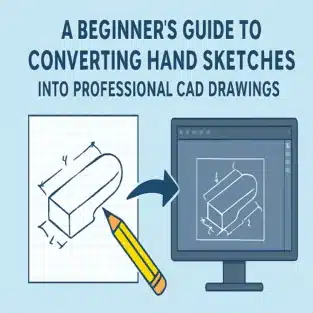
CAD Drawings

Turning hand-drawn sketches into detailed, accurate CAD drawings is one of the most important steps in today’s design, engineering, and construction workflows. Whether you’re an architect sketching a concept on paper, a product designer drawing your first prototype idea, or a homeowner planning renovations, converting a simple sketch into a computer-generated drawing unlocks clarity, precision, and professional quality.

This beginner-friendly guide walks you through the entire process step by step. By the end, you’ll understand exactly how to transform rough sketches into polished CAD drawings ready for manufacturing, construction, or presentation.


Why Convert Hand Sketches Into CAD Drawings?

Hand sketches are perfect for capturing ideas quickly. But for technical execution, you need accuracy. This is where CAD (Computer-Aided Design) comes in.

Here’s why converting your sketches into CAD drawings matters:

  • Precision: CAD software ensures correct dimensions, scale, and alignment.
  • Easy Editing: You can modify, update, or redesign quickly.
  • Professional Presentation: CAD drawings look clean and industry-standard.
  • Compatibility: CAD files can be shared with engineers, manufacturers, or drafting services.
  • 3D Capability: Sketches can evolve into 3D models for visualisation.
  • Digital Archive: No risk of losing or damaging paper sketches.

For beginners, the conversion process may seem complex, but with the right steps, it becomes straightforward.


Step-by-Step Guide: How to Convert Hand Sketches Into Professional CAD Drawings


Step 1: Start With a Clear Hand Sketch

Your final CAD drawing is only as good as your initial sketch.

Tips for creating a clear sketch:

  • Use a pencil or black ink for visible lines.
  • Include basic dimensions (length, width, height).
  • Add notes or labels for specific features.
  • Keep the sketch clean—avoid smudges.
  • Use graph paper for better alignment (optional).

Remember, it doesn’t need to be perfect—just understandable.


Step 2: Scan or Photograph Your Sketch

The next step is to digitise your sketch.

Two simple methods:

1. Scan the Sketch

  • Use any flatbed scanner.
  • Save the file as PNG, JPG, or PDF.

Pros: High clarity and ideal for CAD tracing.

2. Photograph the Sketch

  • Use a smartphone camera.
  • Capture the sketch in good lighting.
  • Hold the camera parallel to avoid distortion.

Tip: Ensure edges are visible and lines are sharp.


Step 3: Import the Image Into Your CAD Software

Most CAD tools allow you to import a raster image (your sketch) and use it as a background layer.

Popular CAD software options:

  • AutoCAD
  • SolidWorks
  • Fusion 360
  • SketchUp
  • Revit (for architectural drafting)
  • LibreCAD (free)

Once imported, scale the image roughly to size. You’ll refine the scale later using dimensions.


Step 4: Trace the Geometry

Now the real drafting begins.

Use CAD tools like:

  • Line
  • Polyline
  • Arc
  • Circle
  • Spline
  • Trim
  • Offset

Follow the sketch lines and trace over them cleanly. This step transitions your rough drawing into professional CAD geometry.


Step 5: Add Dimensions and Annotations

CAD drawings must be dimensionally correct.

Add:

  • Linear dimensions
  • Angular dimensions
  • Radiuses and diameters
  • Notes and labels
  • Title block (if needed)

Make sure every important measurement is accurate. This step ensures your drawing can be used for fabrication or construction.


Step 6: Refine the Drawing

Check for:

  • Overlapping lines
  • Gaps
  • Incorrect snapping points
  • Layer organisation
  • Line weights
  • Symbols and standard conventions

Good practice:

  • Use separate layers for walls, text, dimensions, and centerlines.
  • Apply standard drafting norms (ISO, ANSI, ASME depending on industry).

Step 7: Export the Final CAD Drawing

Once complete, export your drawing into the required formats.

Common file types include:

  • DWG (AutoCAD standard)
  • DXF (universally compatible)
  • PDF (for sharing or printing)
  • STL / STEP / IGES (if 3D modelling is used)

Your hand sketch is now officially a professional CAD drawing ready for real-world use.


Professional Option: Use CAD Conversion Services

If you’re new to CAD or short on time, hiring a CAD conversion service is a smart choice. Drafting professionals can turn your sketch into:

  • Architectural plans
  • Mechanical engineering drawings
  • Product design files
  • 2D and 3D models
  • Construction-ready blueprints

This ensures accuracy, compliance with standards, and fast turnaround.


Tips for Beginners

  • Start with simple shapes and structures.
  • Learn basic CAD shortcuts—they save hours.
  • Keep your layers organised from the beginning.
  • Watch beginner tutorials on your preferred CAD software.
  • Don’t stress over perfection—CAD allows unlimited refinement.

Conclusion

Converting hand sketches into professional CAD drawings bridges the gap between ideas and execution. Whether you’re designing a home, engineering a product, or sketching a creative concept, CAD gives you the precision and professionalism needed for real-world application.

With the steps in this beginner-friendly guide and the right tools (or professional drafting support), anyone can transform a simple sketch into a polished technical drawing.

Can I convert any type of sketch into CAD drawings?

Yes, we can convert almost any sketch into professional CAD drawings, whether it’s architectural layouts, mechanical parts, product concepts, or technical diagrams. Our team works with sketches in various states of completion and can interpret hand-drawn designs to meet Australian building codes, engineering standards, and council requirements. We’ll clarify any unclear details with you to ensure accuracy before finalising your drawings for submission or manufacturing.

Do I need expensive software to create CAD drawings?

Not necessarily. While professional CAD software exists at various price points, many affordable options work well for beginners. Free tools like LibreCAD and FreeCAD are solid choices, and Fusion 360 offers a free personal use license. At ASTCAD, we often recommend starting with these budget-friendly options before investing in premium software. For Australian drafting standards and compliance, we’re happy to guide you through selecting tools that meet local engineering requirements.

How accurate does my hand sketch need to be?

Your sketch doesn’t need to be perfect. As long as the idea and key dimensions are clear, our team can convert it into a precise CAD drawing that meets Australian building codes and engineering standards. We recommend including measurements, angles, and material notes where possible, but we’ll work with you to clarify any details during the conversion process.

What file formats do drafting professionals usually provide?

The most common file formats our Australian drafting professionals deliver are DWG and DXF for 2D drawings, which are industry standards compatible with AutoCAD and most engineering software used across Australia. For projects requiring 3D visualisation or manufacturing, we provide STEP or STL formats. PDF is also standard for client presentations and compliance documentation. We’ll discuss your specific requirements during the initial brief to ensure compatibility with your software and project needs.

Can CAD drawings be turned into 3D models?

Absolutely. Once your sketch is drafted in 2D CAD, it can be extruded or modeled into 3D using software like SolidWorks, Revit, or Fusion 360.


CS

Claire Sutton

Architectural CAD Specialist & Technical Writer · BArch (Hons), QUT · ASTCAD, Brisbane

Claire has 10 years of experience in Revit BIM modelling, architectural documentation, and CAD conversion projects across Southeast Queensland and NSW. She has delivered NCC-compliant documentation for residential, commercial, and industrial facilities.

More articles by Claire Sutton →
CAD drawing guide — AutoCAD blueprints and technical drawings on engineering workstation, Australia

A CAD drawing is a precise digital representation of an object, structure, or system created using Computer-Aided Design software. In Australian engineering and construction practice, CAD drawings are the primary deliverable across mechanical, structural, architectural, civil, and electrical disciplines — replacing hand drafting almost entirely since the late 1990s. This guide covers what CAD drawing is, how it works, the Australian Standards that govern it, and a practical step-by-step process for producing your first professional-grade CAD drawing.

What is a CAD drawing?

A CAD drawing is a two-dimensional or three-dimensional technical representation created using software such as AutoCAD, SolidWorks, Revit, or Fusion 360. Unlike a hand sketch, a CAD drawing is geometrically precise — every line has an exact length, every angle an exact value — and can be scaled, modified, and reused without redrawing from scratch.

In Australian engineering practice, CAD drawings serve different functions depending on their type. A detail drawing shows a single part with full dimensions and material callouts for manufacture. An assembly drawing shows how multiple parts fit together. A general arrangement (GA) drawing shows the overall layout of a system, plant, or building. A fabrication drawing provides all the information a workshop needs to manufacture a component — material, dimensions, weld symbols, surface treatment. Each type follows specific conventions under the Australian Standards for technical drawing.

Australian Standards for CAD drawings — AS 1100

In Australia, all engineering drawings must comply with the AS 1100 Technical Drawing series, published by Standards Australia. This is the Australian equivalent of ISO 128 (general principles of presentation) and defines the conventions, symbols, and notation that make Australian drawings legible to fabricators, certifiers, and engineers across the country.

  • AS 1100.101 — General principles: Line types, sheet sizes (A0 to A4), title block requirements, scale notation.
  • AS 1100.201 — Mechanical engineering drawing: Third-angle orthographic projection, section views, dimensioning conventions, surface texture symbols (Ra), and GD&T.
  • AS 1100.301 — Architectural drawing: North point, grid notation, room naming, symbol conventions.
  • AS 1100.501 — Structural engineering drawing: Reinforcement notation, weld symbols per AS/NZS 1554, structural steel section callouts using Australian designations (UB, UC, RHS, SHS, CHS).

One critical point for Australian drafters: third-angle projection is the default under AS 1100.201. Australian fabricators expect it. If working with European suppliers or clients, the projection symbol must be clearly marked on every sheet — mixing first-angle and third-angle views without explicit notation produces mirrored or inverted parts.

Types of CAD drawings used in Australian engineering

2D CAD drawings

Two-dimensional CAD drawings remain the primary deliverable for fabrication, construction, and approval documentation in Australia. A 2D CAD drawing shows an object using orthographic views — front, top, side — with dimensions, notes, and title block information. Tools used for 2D CAD in Australia include AutoCAD (by far the most common), DraftSight, and MicroStation. 2D CAD drawings are issued as PDF for review and approval, and as DWG or DXF for use by fabricators, CNC machines, and contractors.

3D CAD models and drawings

Three-dimensional CAD modelling is standard for mechanical product design and structural detailing. In SolidWorks, Autodesk Inventor, or Fusion 360, a 3D model is built first, and 2D drawings are then generated from the model. When sharing 3D models between different software packages, the STEP format (AP203 or AP242) is the modern standard — it preserves solid geometry, assembly structure, and optionally GD&T data across all major CAD systems. For architecture and building services, Autodesk Revit produces BIM drawings with embedded data about materials, finishes, and room areas.

Shop drawings and fabrication drawings

Shop drawings are produced by the fabricator (or a drafter on their behalf) from the engineer’s general arrangement drawings. They show how the fabricator intends to manufacture each component — individual member marks, shop and field welds, bolt grades, material grades, and surface treatment. In Australian structural steel practice, shop drawings are submitted to the structural engineer of record for review and approval before fabrication begins. See the fabrication shop drawing checklist for the complete list of items required on an Australian fabrication drawing.

Step-by-step: creating your first CAD drawing

Step 1 — Choose your CAD software

  • AutoCAD — the industry standard for 2D drafting across all disciplines. Used by most Australian drafting firms, fabricators, and contractors.
  • SolidWorks — the dominant 3D CAD platform for mechanical product design in Australian manufacturing, mining equipment, and oil & gas.
  • Autodesk Revit — the standard for architectural and structural BIM in Australian construction.
  • Autodesk Fusion 360 — a good entry point combining 3D modelling, simulation, and CAM in one subscription.
  • Tekla Structures — used by Australian structural steel fabricators and detailers for shop drawing production.

Step 2 — Set up your drawing environment to AS 1100

  • Units: millimetres for mechanical and structural, metres for civil and site work.
  • Sheet size: A1 (841 × 594mm) is the most common for engineering drawings in Australia.
  • Projection type: third-angle — add the projection symbol to your title block.
  • Dimension style: text height 3.5mm at A1 scale, filled arrowheads, decimal separator as a full stop.
  • Title block: every drawing must have drawing title, number, revision, date, scale, sheet size, projection symbol, drafter and checker names per AS 1100.101.

Step 3 — Draw your geometry

Start with the main orthographic views — front, top, and right side — arranged per third-angle projection. In AutoCAD, use LINE, CIRCLE, ARC, RECTANGLE, and OFFSET to build geometry. Keep geometry clean — no duplicate lines, no open polylines, no tiny gaps. For 3D CAD in SolidWorks: sketch on a reference plane, add geometric and dimensional constraints to fully define the sketch, then use Extrude, Revolve, or Sweep to create the solid.

Step 4 — Organise with layers

A well-organised layer structure makes a drawing easier to read, modify, and print. A typical ASTCAD AutoCAD layer structure uses: OUTLINE (0.5mm — visible edges), HIDDEN (0.25mm dashed), DIMENSION (0.25mm), ANNOTATION (0.18mm), HATCH (0.18mm), CENTRELINE (0.25mm chain), and TITLE (0.35mm). Never mix content types on the same layer.

Step 5 — Add dimensions per AS 1100.201

All dimensions in millimetres. Dimension lines minimum 10mm from the nearest visible edge. Overall length/width/height on every part. Reference dimensions in parentheses (150). General tolerance note: “Unless otherwise stated, all dimensions ±0.5mm.” Every hole dimensioned in the view showing it as a circle.

Step 6 — Add annotations, notes, and weld symbols

Beyond dimensions: material callout (e.g. “AS/NZS 3678 Grade 350”), surface treatment (e.g. “Hot-dip galvanise to AS/NZS 4680 after fabrication”), general notes (projection, units, tolerance, drawing standard), weld symbols per AS 1100.501 and AS/NZS 1554, and for structural drawings the weld inspection category (SP or GP per AS/NZS 1554.1).

Step 7 — Check and issue

Before issuing: verify all dimensions are present, check material callouts, confirm title block is complete with revision letter and date, verify weld symbols are correct. In AutoCAD, AUDIT finds and fixes file corruption; OVERKILL removes duplicate geometry. Issue as PDF for review and DWG for use — never issue a CAD file for fabrication without a corresponding PDF at the same revision.

Step 8 — Save in the correct formats

Australian engineering practice uses: DWG (universal 2D CAD exchange), DXF (for CNC and interoperability), PDF (issue, review, approval), STEP or IGES (3D model exchange between different CAD systems), STL (3D printing), and IFC (open BIM format for Revit model exchange). Always include the drawing number and revision in the filename — e.g. ASTCAD-MECH-001-Rev-C.pdf.

Key AutoCAD commands every drafter should know

The most-used AutoCAD commands for drawing production: L (Line), PL (Polyline), C (Circle), O (Offset), TR (Trim), EX (Extend), M (Move), CO (Copy), MI (Mirror), RO (Rotate), F (Fillet), CHA (Chamfer), H (Hatch), DLI (Dimension Linear), DCO (Dimension Continue), DRA (Dimension Radius), DDI (Dimension Diameter). Learning keyboard shortcuts rather than clicking through menus is what separates a fast professional drafter from a slow beginner.

Common CAD drawing errors and fixes

  1. Wrong projection symbol. Always show third-angle on Australian drawings. Mark first-angle explicitly when working internationally.
  2. Dimensions not in millimetres. A drawing produced in inches shared with an Australian fabricator will produce parts 25.4× the wrong size if the unit mismatch isn’t caught.
  3. Open geometry. Unclosed polylines cause hatching to fail and CNC toolpaths to break. Use BOUNDARY and PEDIT to close geometry before issuing.
  4. Missing material callout. Use specific specifications: “AS/NZS 3678 Grade 350” not just “steel”.
  5. Scale not stated on detail views. When a detail is at a different scale from the main drawing, state the scale adjacent to the view title.
  6. No revision cloud on updated drawings. Cloud the changed area and update the revision table on every re-issue.

Frequently asked questions

What is the difference between a CAD drawing and a CAD model?

A CAD model is a three-dimensional digital object — a solid, surface, or wireframe representation. A CAD drawing is a two-dimensional orthographic representation with dimensions, annotations, and title block information. The drawing is the document issued for fabrication or approval; the model is the design tool. In SolidWorks and Inventor, the 3D model is built first, then the 2D drawing is generated from it.

Does Australia use first-angle or third-angle projection?

Australia uses third-angle projection as the default per AS 1100.201. In third-angle, the right side view appears to the right of the front view and the top view appears above. Europe uses first-angle (ISO). The projection symbol must always be shown on Australian drawings — especially important when drawings may be sent to international suppliers.

What file format should Australian CAD drawings be issued in?

Issue as PDF (review, approval, printing) and DWG (contractor and fabricator use). For 3D model exchange, STEP (.stp) is the most universally accepted neutral format; IGES (.igs) is the legacy alternative. For CNC cutting, use DXF. Always include drawing number and revision in the filename.

How long does it take to learn CAD drawing professionally?

Basic 2D drawings in AutoCAD: 2–4 weeks of daily practice. Professional fabrication drawings to AS 1100: 3–6 months of hands-on work. Full 3D CAD proficiency (SolidWorks or Inventor): 12–18 months. ASTCAD’s drafter recruitment service can place experienced CAD drafters immediately when training time isn’t available.


Related resources: Engineering Drawing Guide — AS 1100 | Fabrication Shop Drawing Checklist | Sheet Metal Design Handbook | CAD Drafting Services

JH

James Hartley

Senior Mechanical Engineer · BEng (Mechanical), UQ · Member, Engineers Australia · ASTCAD, Brisbane

James has 14 years of hands-on experience delivering CAD design, structural drafting, and engineering documentation across Australia’s mining, oil & gas, and manufacturing sectors. He specialises in SolidWorks, Autodesk Inventor, and AutoCAD for complex multi-discipline projects.

More articles by James Hartley →
AutoCAD

Structural design and drafting are the backbone of any construction or engineering project. With the rise of digital tools, AutoCAD has become one of the most powerful and widely used software platforms for creating precise 2D and 3D structural drawings. Whether you are an aspiring civil engineer, architect, or draftsman, learning Structural Design and Drafting in AutoCAD will open countless career opportunities and help you work efficiently on real-world projects.

In this complete guide, we’ll walk you through the basics of structural drafting in AutoCAD, key tools, best practices, and FAQs to help beginners get started.


What is Structural Design and Drafting in AutoCAD?

Structural design involves planning, analysing, and designing the load-bearing framework of a building, bridge, or any structure. Drafting, on the other hand, is the process of creating detailed technical drawings that communicate the design intent to builders, engineers, and contractors.

AutoCAD allows engineers and draftsmen to create precise and scalable structural drawings digitally. It replaces manual paper drawings, saving time and reducing errors while providing flexibility for modifications and collaboration.


Why Use AutoCAD for Structural Design and Drafting?

  1. Accuracy and Precision – AutoCAD ensures millimeter-level accuracy in structural drawings.
  2. 2D & 3D Modelling – It offers both 2D drafting and 3D modelling for a complete design experience.
  3. Standardisation – AutoCAD supports industry standards, symbols, and templates.
  4. Easy Editing – Unlike manual drawings, changes can be made quickly and efficiently.
  5. Compatibility – AutoCAD drawings can be shared in multiple formats (DWG, DXF, PDF) for collaboration.

Getting Started with Structural Drafting in AutoCAD

If you are a beginner, follow these essential steps to start creating structural drawings in AutoCAD:

1. Learn the Basics of AutoCAD Interface

  • Explore the ribbon menu, command line, and drawing workspace.
  • Familiarize yourself with layers, object snaps, and coordinate systems.

2. Understand Structural Drafting Standards

  • Learn common structural symbols (beams, columns, foundations, reinforcements).
  • Follow BIS, AISC, or regional drafting standards.

3. Create the Structural Grid

  • The grid forms the base of any structural drawing.
  • Use LINE and OFFSET commands to set up grids.

4. Draft Structural Elements

  • Columns – Draw using rectangles or polylines.
  • Beams – Use lines or polylines aligned with the grid.
  • Footings & Foundations – Represent with rectangles and hatch patterns.
  • Slabs & Reinforcement – Use hatches and layers for clarity.

5. Use Layers Effectively

  • Assign beams, columns, slabs, and dimensions to separate layers.
  • Helps in organising and editing the drawing.

6. Add Dimensions and Annotations

  • Use the DIMLINEAR and TEXT commands for clarity.
  • Ensure all drawings are readable with proper scale.

7. Create 3D Structural Models (Optional)

  • AutoCAD’s 3D tools can be used to visualise the structure.
  • Commands like EXTRUDE and REVOLVE help in creating 3D models.

8. Finalise and Export Drawings

  • Double-check alignment, dimensions, and standards.
  • Export in PDF/DWG format for engineers and contractors.

Best Practices for Beginners

  • Always start with proper units and scales.
  • Use blocks for repetitive elements like column sections.
  • Keep drawings clean and organised with layers.
  • Save your work frequently to avoid data loss.
  • Learn keyboard shortcuts to speed up drafting.

Benefits of Learning Structural Design and Drafting in AutoCAD

  • Enhances employability in civil engineering, architecture, and construction industries.
  • Saves time compared to manual drafting.
  • Helps in creating error-free, professional drawings.
  • Builds a strong foundation for learning advanced software like Revit or STAAD Pro.

Final Thoughts

Learning Structural Design and Drafting in AutoCAD is a rewarding skill that empowers beginners to create accurate, professional, and standardised drawings for construction projects. By mastering the basics—grids, columns, beams, dimensions, and annotations—you can progress toward advanced modelling and even BIM applications.

AutoCAD remains one of the most in-demand tools in engineering and construction, making it a valuable career asset. Whether you are a student, fresher, or professional, this guide gives you a roadmap to start your journey in structural drafting.

What is structural design and drafting in AutoCAD?

Structural design and drafting in AutoCAD involves creating detailed technical drawings of buildings, bridges, and infrastructure projects that comply with Australian Standards and Building Codes. Our experienced team uses AutoCAD to produce comprehensive plans, elevations, sections, and reinforcement details that help engineers, builders, and contractors accurately understand and execute the design. These drawings are essential for obtaining council approvals and ensuring your project meets National Construction Code requirements.

Why is AutoCAD important for structural drafting?

AutoCAD is essential for structural drafting because it delivers the precision and accuracy required for Australian building codes and standards. We use AutoCAD to create detailed 2D and 3D drawings efficiently, make rapid design modifications, and seamlessly collaborate with engineers, architects, and contractors. The software allows our team to produce compliant construction documentation while meeting strict AS/NZS requirements, ultimately saving time and reducing costly errors on site.

Can beginners learn structural drafting in AutoCAD?

Yes, absolutely. We recommend beginners start with fundamental 2D drafting techniques, master layer organisation and dimensioning standards, then progress to structural detailing. Following Australian building codes and engineering practices, our clients successfully create professional structural drawings through consistent practice and our tailored tutorials.

What skills are needed to start structural design in AutoCAD?

To start structural design in AutoCAD with ASTCAD, you’ll need basic construction knowledge, understanding of structural elements like beams and columns, and AutoCAD command familiarity. We recommend learning Australian building codes and standards, particularly AS/NZS 1170 for loads and the National Construction Code. Our team suggests practicing with local project examples to understand how Australian specifications apply to your designs.

What types of structural drawings can be created in AutoCAD?

We can help you create a comprehensive range of structural drawings in AutoCAD, including foundation plans, column layouts, beam details, and reinforcement drawings that comply with Australian Standards. Our team specializes in steel structure details, concrete specifications, and detailed 3D structural models tailored to meet local building codes and engineering requirements. Whether you’re designing residential, commercial, or industrial projects, AutoCAD allows us to produce accurate, professionally detailed drawings ready for construction and council approval.


JH

James Hartley

Senior Mechanical Engineer · BEng (Mechanical), UQ · Member, Engineers Australia · ASTCAD, Brisbane

James has 14 years of hands-on experience delivering CAD design, structural drafting, and engineering documentation across Australia’s mining, oil & gas, and manufacturing sectors. He specialises in SolidWorks, Autodesk Inventor, and AutoCAD for complex multi-discipline projects.

More articles by James Hartley →
Get a free quote — 1800 287 223