Engineering problems with Finite Element Analysis (FEA)
With finite element analysis or FEA services, you can easily find an apt solution for any complex engineering problem by subdividing your problem into small and manageable finite elements. FEA services involve the use of finite elements to successfully reduce the complex differential equations of a structure to a set of easily solvable linear equations.[/fusion_text][fusion_text]In short, finite element analysis can be described as an engineering technique that is used to predict the response of structures and materials to applied loads such as temperature, force, displacements and vibration. Before you develop a design, you can model it, evaluate its performance and address failure points with FEA services.
Engineering problems with Finite Element Analysis (FEA)
Today, almost every engineering discipline requires finite element analysis. Industries like manufacturing, plastics, electronics, energy, geotechnical aerospace, automotive, biomedical and chemicals regularly use FEA services. Apart from playing an integral role in evaluating classical static structural problems, FEA is also widely used in radiation problems, mass transport, dynamics and heat transfer amongst others.
ASTCAD offers cutting-edge FEA services
If your organization wants to optimize a new design, verify the fitness of an existing facility or evaluate a new concept, then you can opt for finite element analysis services from ASTCAD Design & Drafting. Accurate FEA services require the skills of experienced analysts and advanced technologies. ASTCAD can provide you with world-class FEA services at an affordable price. Over the years, ASTCAD has earned the reputation of having the world’s best engineers and access to sophisticated analysis tools.
Get complete FEA solutions from ASTCAD
ASTCAD have the best personnel, latest equipment and cutting-edge tools to perform comprehensive finite element analysis, such as:
- Mechanical drop and impact analysis
- Modal analysis and forced vibration (Sine and Random)
- Thermo-mechanical analysis (Fatigue and Creep)
- Parametric sensitivity analysis
- Warpage analysis
- Material stiffness analysis
- Shock Spectrum analysis
Top 5 benefits of outsourcing FEA services
By outsourcing finite element analysis services to ASTCAD, your organization can leverage the following five benefits:
- Drastically reduce your development time and the cost of new products
- Get valuable product reliability insights
- Improve the quality of the product
- Easily conduct and simulate conditions like temperature cycling, drop, vibration and fatigue life tests
- Investigate and quantify different design scenarios ( varying geometries, changing materials etc)
Engineering problems with Finite Element Analysis (FEA)
By partnering with ASTCAD for FEA services, your company can enjoy fast, accurate and professional finite element analysis services at a low cost. With access to expert FEA structure stress analysis, engineering design and simulation using CAD, you can solve your engineering problems. From the initial concept to the final product launch, you can be sure of 100% customer satisfaction, when you partner with ASTCAD for FEA services.
Finite Element Analysis (FEA) is a powerful numerical method used to solve engineering problems by simulating the behavior of structures or systems under various conditions. Here’s a general approach to solving engineering problems with FEA:
- Problem Identification: Clearly define the engineering problem you want to solve. Identify the objectives, constraints, and desired outcomes of the analysis. Determine the specific components or systems that need to be analyzed using FEA.
- Geometry and Mesh Generation: Create a digital model of the structure or system using CAD software or FEA-specific pre-processing tools. Define the geometry, including dimensions, shapes, and boundaries. Divide the model into smaller elements and create a mesh, ensuring appropriate element size and quality.
- Material Properties and Boundary Conditions: Assign material properties to the elements, including properties such as elasticity, density, thermal conductivity, and other relevant parameters. Apply appropriate boundary conditions, such as fixed supports, loads, displacements, or thermal conditions, based on the physical behavior of the system.
- Element Selection and Analysis Type: Choose suitable finite elements based on the problem type, such as truss, beam, shell, or solid elements. Select the appropriate analysis type, such as static, dynamic, thermal, or nonlinear analysis, based on the nature of the problem and the behavior of the structure.
- Solver Configuration: Set up the solver parameters, including convergence criteria, time steps, and solution options. Specify any additional assumptions, simplifications, or idealizations required for the analysis.
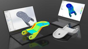
- Solve and Post-Processing: Run the analysis using the FEA software. The software will calculate the response of the structure or system based on the applied loads, boundary conditions, and material properties. Once the analysis is complete, examine the results to understand the behavior of the structure, including stress, strain, displacement, temperature distribution, or other relevant output parameters.
- Interpretation and Validation: Analyze and interpret the results in relation to the problem objectives. Validate the results by comparing them to theoretical calculations, experimental data, or industry standards. Assess the accuracy, reliability, and limitations of the FEA analysis.
- Optimization and Design Iteration: If the analysis reveals areas of concern or performance gaps, consider design iterations or optimizations to improve the structure’s performance. Modify the geometry, material properties, or boundary conditions as needed and repeat the FEA analysis to evaluate the effects of the changes.
- Documentation and Reporting: Document the analysis process, including the problem statement, assumptions, modeling details, input parameters, results, and conclusions. Prepare a comprehensive report that summarizes the analysis methodology, findings, and recommendations.
Have you outsourced mechanical engineering services before? If yes, how did it go? Would you consider outsourcing FEA services? Let us know your thoughts, views and questions on outsourcing to ASTCAD by leaving a comment in the box below. We, at ASTCAD love, to hear from you!