DESIGN DRAFTING SERVICE We at Australian Design and Drafting Services, possess the relevant resources, experience and capabilities to provide a one-stop shop platform to the clients be it Concept drawing, producing drawings for mechanical projects, providing manufacturing drawings in either 2D or 3D format of various mechanical assemblies or 2D to 3D drawings Conversions, addition of geometric dimensions, annotations, other tolerance related information, Bill of Material to any type and format of mechanical engineering drawings. Belonging to same field, we realize the potential of parametric modeling in terms of providing flexibility when designing and managing any product.We provide design drafting service. It is crucial to have a team on board who understands clearly the concepts of designing and manufacturing any product and thereby producing product specific CAD drawings. Our professional and dedicated team of highly qualified Mechanical engineers possess the relevant knowledge of prototyping and manufacturing industries. We provide client specific customised design and drafting services. Whether you require 2D Drafting services or a simple 2D to 3D or vice versa CAD Conversion Service, we have cost-effective solutions for all your design drafting needs.
Computer Aided Design (CAD) & Drafting Services in Australia
ASTCAD provides professional computer aided design (CAD) and drafting services to engineering, construction and manufacturing clients across Australia. Our CAD services cover all major disciplines — mechanical, structural, architectural, civil and electrical — using the industry’s leading software packages with offices in Brisbane, Sydney, Melbourne, Perth and Gold Coast.
What Is CADD? Computer Aided Design and Drafting Explained (2026 Guide)
Computer-aided design and drafting (CADD)
Computer-aided design and drafting (CADD) is the process of using a computer with CADD software for design and drafting applications. Software is the program or instructions that enable a computer to perform specific functions to accomplish a task. CADD refers to the entire range of design and drafting with the aid of a computer, from drawing basic 2-D objects to preparing complex 3-D models and animations. CAD is the acronym for computer-aided design and a common reference to computer-aided drafting. Computer-aided design and computer-aided drafting refer to specific aspects of the CADD process.
CADD offers solutions to most engineering drawing and design problems, and it allows for increasingly complex projects. Several industries and most disciplines related to engineering and architecture use CADD. Most engineering firms and educational institutions that previously used manual drafting practices have evolved to CADD. Professionals have come to rely on the power and convenience of CADD in all aspects of design and drafting. CADD systems include tools to accomplish any drawing and design requirement, such as preparing the 3-D model of a home shown in Figure.
The CADD workstation
The CADD workstation consists of a variety of computer hardware. Hardware includes the physical components of a computer system, such as the computer, monitor, keyboard, mouse, and printer. The figure shows a modern CADD work-station. A CADD workstation relies on a computer for data processing, calculations, and communication with peripheral equipment. A peripheral is an external computer hardware device that uses the computer to perform functions that the computer cannot handle. Peripherals provide input, output, and storage functions and services. Input means to put information into the computer that the computer acts on in some way. Input comes from devices such as the keyboard, a mouse or similar input device, or a digitizer. Output refers to information that the computer sends to a receiving device such as a monitor, a plotter, or a printer. Storage refers to disks and drives that allow the operator to store programs, files, symbols, and data.
CADD software products
The modern CADD workstation is powerful, inexpensive, and supports sophisticated CADD software. Many CADD software manufacturers exist, and numerous products are available to meet industry needs. Some CADD software is general purpose and can apply to any discipline. For example, Autodesk, Inc. produces AutoCAD for 2-D and 3-D design and drafting.
Other products focus on a specific CADD technology, industry, or discipline, such as drawings or models of mechanical parts and assemblies or those for architectural, civil, or structural engineering projects.
For example, Dassault Systèmes SolidWorks Corp. offers SolidWorks for 3-D solid modelling and 2-D drafting that is common in the manufacturing industry. Software specifically designed for CADD in the manufacturing industry is sometimes referred to as mechanical computer-aided design (MCAD) software. Some CADD programs support expanded, third-party, or add-on utilities intended to increase system usefulness for specifi c applications. The CADD software industry changes constantly. Software manufacturers frequently update existing products or combine, change program names, or eliminate programs to adapt to the rapidly evolving CADD market. Software updates typically include additional and refined tools, increased software stability, and graphical user interface (GUI) enhancements.
Computer Aided Design and Drafting
The interface describes the items that allow you to input data to and receive outputs from a computer system. The GUI provides the on-screen features that allow you to interact with a software program. New products regularly emerge to respond to innovative technology and project requirements. Larger software manufacturers, such as Autodesk Inc., Dassault Systèmes, Parametric Technology Corporation, and Siemens PLM Solutions hold the greatest number of CADD users, and they traditionally have the ability to expand their products and acquire smaller software companies or existing software.
ASTCAD provide excellent service for CAD Design and Drafting. Contact Us for more info
What is computer-aided design and drafting?
Computer-aided design and drafting (CADD), also known as computer-aided design (CAD), refers to the use of computer software to assist in the creation, modification, analysis, or optimization of designs for a wide range of applications. CAD software allows designers, engineers, architects, and other professionals to create precise 2D drawings or 3D models of objects, buildings, mechanical parts, electrical circuits, and more.
What is computer aided drafting CAD used for?
Computer-aided drafting (CAD) is used in architecture and construction, mechanical engineering, product design and manufacturing, electrical and electronic systems, interior design, urban planning, and aerospace and automotive industries.
James has 14 years of hands-on experience delivering CAD design, structural drafting, and engineering documentation across Australia’s mining, oil & gas, and manufacturing sectors.
Manual drafting — drawing by hand using pencils, technical pens, drawing boards, T-squares, set squares, and drafting machines — was the universal method for producing engineering drawings before CAD software became mainstream in the 1980s and 1990s. While manual drafting has been almost entirely replaced by computer-aided design (CAD) in professional engineering and construction practice, understanding its tools, techniques, and conventions remains relevant: many of the conventions used in manual drafting (line weights, symbol libraries, dimensioning rules) were directly inherited by CAD standards including AS/NZS 1100.
Manual Drafting Equipment and Supplies
Tool
Purpose
Drawing board
Flat, stable surface — typically A1 or A0 size. Adjustable tilt for comfortable working angle.
T-square
Slides along the drawing board edge to draw precise horizontal lines. The vertical reference for all other geometry.
Set squares (45° and 30°/60°)
Used against the T-square to draw lines at 45°, 30°, 60°, and 90° angles.
Drafting machine
Replaces T-square + set squares. Locks to a reference angle and can be rotated to any heading. Faster for complex geometry.
Compass
Draws circles and arcs by rotating around a fixed centre point.
Dividers
Transfer measurements from scale rule to drawing surface without marking.
Scale rule (triangular)
A triangular ruler with multiple scale ratios (1:1, 1:2, 1:5, 1:10, 1:20, 1:50, 1:100, 1:200) for reading and drawing to scale.
Technical pens (Rotring)
Produce consistent line widths (0.18, 0.25, 0.35, 0.5, 0.7, 1.0mm) on drafting film or paper. ISO standard line widths.
Pencils (H grades)
H, 2H, 4H for construction lines; HB for lettering and annotation.
Drafting templates
Pre-cut shapes (circles, ellipses, symbols) for fast repetitive drafting.
Erasing shield
Thin metal sheet with cut-outs allowing precise erasing without damaging adjacent lines.
French curves
Plastic templates for drawing smooth irregular curves.
Lettering guides
Stencils for consistent text height and spacing — important before CAD text tools existed.
Manual vs CAD Drafting: Key Differences
Manual Drafting
CAD Drafting
Medium
Drafting paper, vellum, polyester film
Digital — DWG, DXF, PDF files
Speed
Slow — complex drawings take days or weeks
Fast — changes update automatically
Modifications
Time-consuming — erase and redraw
Instant — move, copy, scale at will
Accuracy
Limited by hand steadiness and tool precision
Exact — coordinates to 14 decimal places
Reproducibility
Blueprint (ammonia process) or photocopying
Unlimited prints, PDFs, DXF files
Collaboration
One person drawing at a time; overlays for multi-discipline
Multiple users, cloud sharing, version control
3D capability
Isometric views only — no true 3D
Full 3D solid modelling (SolidWorks, Revit)
Standard compliance
Manual application of AS/NZS 1100 rules
Built into CAD templates and dimension styles
When Is Manual Drafting Still Used?
Manual drafting is effectively obsolete in professional engineering and construction in Australia. The last significant professional use was in the early-to-mid 1990s, when AutoCAD and MicroStation displaced drawing boards across most firms. Today, manual drafting techniques appear in:
Engineering and architecture education — first-year students often learn hand drafting to understand the underlying conventions before moving to CAD
Conceptual sketching — designers still sketch by hand to explore ideas quickly before committing to CAD
Remote site marking up — annotating printed drawings on site when a laptop isn’t available
Heritage documentation — drawing existing historic buildings or structures from physical measurement
Emergency/field conditions — sketching dimensions of components for urgent replacement ordering
Manual Drafting Conventions Inherited by CAD
CAD software didn’t invent its drawing conventions — it automated the conventions that manual drafters spent decades developing. All of the following originated in manual practice and are now codified in AS/NZS 1100:
Line weights — thick lines for visible edges (0.5mm), thin lines for dimensions and hidden lines (0.25mm), chain lines for centrelines
First/third angle projection — the arrangement of orthographic views on a drawing sheet
Title block layout — drawing number, revision, scale, projection symbol in the bottom-right corner
Dimensioning rules — extension lines, arrowheads, dimension text above the line, chained vs baseline dimensioning
Hatch patterns — 45° diagonal lines at specific spacing to indicate cut surfaces in section views
Symbol libraries — weld symbols, surface finish marks, GD&T feature control frames
Converting Manual/Paper Drawings to CAD
Many Australian manufacturers, mining companies, and infrastructure operators hold large archives of historical manual drawings — often on vellum or polyester film — that need to be digitised. This process, called CAD conversion, involves:
Scanning — high-resolution scanning of the original drawing
PDF clean-up — removing fold marks, stains, and degradation artefacts
CAD redrafting — redrawing the geometry in AutoCAD or other software, either manually from the scan or using PDF-to-DWG conversion tools with human QA
Dimensioning and annotation — verifying and adding dimensions, notes, and title block data
QA check — comparing the CAD output against the original scan for accuracy
ASTCAD provides paper-to-CAD and PDF-to-DWG conversion services across all disciplines — mechanical, structural, architectural, and civil. All output is delivered in DWG format to Australian Standards (AS/NZS 1100).
James has 14 years of experience delivering CAD design, structural drafting, and engineering documentation across Australia’s mining, oil & gas, and manufacturing sectors.
A drafting professional is more than a CAD operator. There is a significant difference between an individual trained in the theories, principles, standards, and requirements of the career field and a true professional. Being a professional is more than holding a credential. A certificate or diploma is only an indication of knowledge in the area you have chosen to study. Many recently educated people search for a large salary, but they generally have only a moderate understanding of their career field and little or no training as a true professional.
The facts are simple. When employed, you typically sign an agreement indicating job requirements, work times, vacations, sick days, insurance provisions, and employer expectations.
Many employers have a dress code, a code of ethics, and other provisions you must follow. As an employee, you are an adult who is being paid to make things happen. You are a part of a working machine, but you are not the main wheel that makes it turn. Do your job, do it well, and keep the wheels turning, which is your primary function in an entry-level position.
In becoming a true professional, you need to keep in mind that with the availability of the Internet and other media, that your potential employer can check up on you and in many cases find out more than you want them to know. Facebook, MySpace, blogs, and other social networking areas on the Internet can be very damaging to your career if misused. As with your professional attitude, you need to keep some things private.
Professional network
You do need a professional network, and there are many of them such as LinkedIn or Plaxo that can help you network on a professional level. Now is the time to exhibit responsibilities to yourself and your employer.
In my current role, I am in constant contact with the leaders of the industry, representing some of the most prestigious manufacturing, engineering, architectural, and industrial firms in the world. When discussing the employment of future drafters and designers, I often request information on the reasons one individual is chosen over another when they are equally qualified. The answer is consistent; they employ those who reflect professionalism in all aspects of their individuality and areas of training.
Professional facts
The following are 15 facts that make you a professional:
You must understand that your education begins after you have achieved your Your credentials only expose you to the knowledge and skills needed to perform the job. Real learning comes from day-to-day experience over many years.
Consider the interview process, the interviewer, and the type of company when seeking to Investigate the company and determine what they do, their geographic area, and who owns the company. The company mission and employee expectations should match your goals and objectives.
If you are seeking a career, do not take a job just to be Dissatisfaction may show in your work and performance, and it may result in you seeking new employment or being terminated. Employment changes can make it difficult to becoming reemployed. You should always keep a position for two or more years.
Leave your attitude at You should show gratitude for your employment. Be proud that this company thinks you have the potential to be a part of its working family. Keep in mind that you are not the owner.
Keep your opinion to yourself, focus on your job, and shape your This will bring you more attention and give you more excellent opportunities. Share improvement ideas with your supervisor. Ask if your work is acceptable and if there is anything that you can do better. Accept criticism with modesty.
Many co-workers will do anything to advance, which is an unethical fact of survival in This activity can lead to discontent. Remember, you work for your supervisor, your job is to improve the product, produce a product, and increase company profits. Negative actions toward you by co-workers reflect their own inability to carry out their duties.
Acting professional is a big part of your new You hold credentials, and with them comes a code of ethics that professionals follow. Here are some guidelines: (1) Be at your workstation, the computer turned on, chair adjusted, and ready to work a few minutes before work time. (2) Take your breaks at the designated. This is when you typically go to the restroom, get a coffee refill, or eat a snack. Work time is for production. (3) Your scheduled lunchtime includes You may find it more convenient to eat at work and have time to relax or do personal things. (4) Quitting time can be exciting, but do not stop early just to be out the door at 5 P.M. sharp. Complete a project and then deliver it to your supervisor if it takes a few minutes. You will have a head start on tomorrow and your career.
Dress well for your interview and on the job, providing a professional Men should wear a shirt and tie, jacket, dress pants, and polished leather shoes with laces. Women should wear professional style clothing, fitting to the employment atmosphere. Women should avoid wearing dresses for the interview. Women should wear dress pants or a skirt, blouse, and matching jacket, or a pants suit, and avoid necklines more than four fingers below the high point of your sternum. Patent leather or athletic shoes should not be worn by either sex. Shoes should coordinate with your clothing and should be flats or low heels. Avoid noisy shoes. Wear professional colour such as navy, black, or grey. Do not wear a white, yellow, or chartreuse jacket. Your shirt or blouse should be white, light blue, or a pastel colour. Men should wear a tie that coordinates with the jacket and pants and wear a belt that matches shoe colour. In today’s liberal workforce, unisex clothing is readily available, and some of it looks sharp. However, in the interview process, make sure your clothing is cut to fit your body style. Accessories should be moderate, with no visible necklaces or dangling earrings. Cologne and perfume should be very subdued. For men and women, exposed body piercings in your nose, lips, and tongues and multiple sets of earrings should not be worn at the interview.
Personal choices should be used on personal time or when found to be acceptable. Otherwise, you could jeopardize your employment opportunity. Keep in mind, you are applying for a job, and you do not know the preference of the company or the interviewer. The company makes the rules. Do not try to change policy if you want to keep your place. Observe the company dress code, so you know how to dress when you are employed.As a new hire, you should dress conservatively even if you see others are wearing jeans and polo shirts. If every- one wears shirts and ties, you do the same and make sure you have a jacket. Having a jacket or sport coat is good in case you need to attend a meeting. If the job requires you to go to manufacturing or to the field, you should have an appropriate change of clothes or cover-up. Finally, regardless of the dress code, keep a change of clothes in your car and be ready for an emergency dress up or dress down in a few minutes.
Self-improvement is a good investment in the job. Research on work, processes, clients, and another project-related issue while on your own time. This can improve your production, broaden your mind, discover new project ideas, find software solutions and production methods, or network with other professionals.
Most employment communication is proprietary and should not be discussed with anyone other than your supervisor or involved co-workers. Do not take information from work to home, unless approved by your supervisor.
Write personal e-mails and make personal phone calls after work or on your personal cell phone outside the of- fice during break or at lunch. Using company equipment and company time is only for company business.
After employment, you need to start preparing for you next move up the career ladder. Your employer may offer educational benefits. If you have access to the Internet at home, you can do webinars and take online training and technical training or expand your formal education. Your new knowledge, ability to speak on the technical subjects, and performance at work indicate your improvement without bragging. Provide information about your expanded learning during your annual reviews.
Completion of your education is only one step in the overall progression of your career track. You should seek industry certification with a professional organisation. Certification is based on industry standards and required knowledge at a specific level in the profession, and it is offered by industry organisations who are experts in the field. Certification competencies provide minimum performance and knowledge levels to your employer. Certifications can be related to software, codes, standards, technical writing, and other subjects. Additional training reinforces your abilities and your employability.
Keep a work journal as an organisational tool and to improve your growth as a professional. Include specific assignment information, assignment performance, individuals involved, specific times and places related to the assignment, when you go to lunch, change projects, talk to a co-worker about a previous project, or attend a meeting about a new project. Entries made by time and date will stand firm in a challenge. The more you document, the better.
While in school and after, you should be a member of any professional organisation that relates to your profession. ADDA and Skills USA offer student memberships for the drafting profession. By being involved in professional associations, you will find a network of professionals who can assist you in every phase of your career path and offer opportunities, advice, and guidance you cannot receive anywhere else. As you leave your school and enter the workforce, you should retain your membership in the professional organisation and become as active as possible.
Most organisations provide you with professionally rewarding volunteer opportunities on committees and groups to assist the profession. As you gain experience, you will see yourself working on projects with little assistance, moving up the corporate steps, being given more responsibility and increased compensation, and having opportunities you hoped for when you were first employed.
Summery
The following summarizes our profession:
Drafting is the foundation and stepping-stone of any aspiring architect and engineer. It is a tedious profession, with days filled with non- stop drawing and making models of designs. It is through this process that one is able to learn to develop new skills and be introduced to styles that can be used as inspiration for personal design preferences in the future. Drafting moulds the builders and designers of the future. Drafting is the profession of the hardworking and the persevering, the patient and the creative, the ambitious and the proud.
James has 14 years of hands-on experience delivering CAD design, structural drafting, and engineering documentation across Australia’s mining, oil & gas, and manufacturing sectors. He specialises in SolidWorks, Autodesk Inventor, and AutoCAD for complex multi-discipline projects.
A CAD drafter (also called a CAD technician, CAD designer, or drafting technician) is a technical professional who uses computer-aided design software to produce precise engineering drawings, models, and technical documentation. In Australia, CAD drafters work across mechanical, structural, civil, architectural, and electrical disciplines — translating engineer and architect designs into detailed, buildable drawings.
What Does a CAD Drafter Do?
The day-to-day work of a CAD drafter varies by discipline, but typically includes:
Producing 2D engineering drawings from sketches, specifications, or 3D models (detail drawings, assembly drawings, general arrangement drawings)
Building 3D CAD models in SolidWorks, Inventor, Revit, or AutoCAD
Adding dimensions, tolerances, material callouts, weld symbols, and notes to drawings
Coordinating with engineers, architects, and fabricators to resolve drawing queries
Updating drawings to incorporate design revisions, issuing revision-controlled drawing sets
Converting old manual or paper drawings to CAD format
Producing shop drawings and fabrication drawings for manufacture
Maintaining drawing registers and document control systems
CAD Drafter Education and Qualifications in Australia
Qualification
Level
Duration
Outcome
Certificate III in Engineering — Technical (MEM30219)
VET / TAFE
1–2 years
Entry-level drafter — 2D AutoCAD focus
Certificate IV in Engineering (MEM40119)
VET / TAFE
1–2 years
Mid-level — broader engineering context
Diploma of Engineering — Technical (MEM50219)
VET / TAFE
2 years
Senior drafter / junior designer level
Advanced Diploma of Engineering (MEM60119)
VET / TAFE
2–3 years
Design engineer / project lead level
Bachelor of Engineering Technology
University
3 years
Engineering technologist — can progress to CPEng
Bachelor of Engineering (Honours)
University
4 years
Professional engineer — may start as drafter
In practice, most Australian CAD drafters enter through TAFE — the Certificate III or IV in Engineering is the most common pathway. Software training (AutoCAD, SolidWorks, Revit) is typically learned through short courses, on-the-job training, or vendor-specific certification programs. There is no licensing requirement to work as a CAD drafter in Australia, though Engineers Australia membership and CPEng registration apply to the engineers who sign off drawings.
CAD Software Skills for Australian Drafters
Software
Discipline
Employer demand (AU)
AutoCAD
All disciplines — 2D drafting
Very High
Revit
Architecture, structural, MEP — BIM
Very High
SolidWorks
Mechanical, manufacturing
High
Autodesk Inventor
Mechanical, manufacturing
High
Civil 3D
Civil engineering, infrastructure
High
MicroStation
Infrastructure, government, Pilbara resources
Medium-High
12D
Civil engineering, surveying
Medium
CATIA
Aerospace, automotive, defence
Medium
Tekla Structures
Structural steel detailing
Medium
ArchiCAD
Architecture (smaller firms)
Low-Medium
CAD Drafter Salary in Australia (2026)
Level
Experience
Typical salary range (AUD)
Junior CAD drafter
0–2 years
$55,000 – $70,000
Intermediate CAD drafter
2–5 years
$70,000 – $90,000
Senior CAD drafter / lead
5–10 years
$90,000 – $110,000
CAD designer / principal
10+ years
$110,000 – $130,000+
Contract drafter (daily rate)
Varies
$350 – $650/day
Salaries vary significantly by location (Perth and Darwin typically pay 10–20% above Brisbane/Sydney/Melbourne for resource-sector roles), discipline (mechanical and structural tend to pay more than architectural), and the specific software stack demanded.
Job Opportunities for CAD Drafters in Australia
CAD drafters are employed by engineering consulting firms, architectural practices, construction companies, mining and resources companies, manufacturers, government agencies, and specialist drafting firms like ASTCAD. The strongest demand is currently in:
Structural steel detailing — driven by construction activity across major cities and resources infrastructure
Revit BIM coordination — tier-1 contractors now mandate BIM on most major projects
Civil infrastructure — roads, rail, water treatment, and renewable energy projects
Mining and resources — particularly in Western Australia (AutoCAD, MicroStation)
Defence industry — AUKUS and major defence procurement driving demand in Adelaide and Brisbane
James has 14 years of experience delivering CAD design, structural drafting, and engineering documentation across Australia’s mining, oil & gas, and manufacturing sectors.
Reusability in CADD offers essential benefits. By using CADD, it’s necessary to draw anything more than once. Developing a CADD symbols library enhances the ability to reuse all the content. It built a part of the library for reusability with increased productivity. It decreases the development costs and sets the highest standards for Measurement Documentation.
The parts of the library can reuse 3D isometric parts to create the CADD illustrator. It is saved as symbols in a parts library directory. By pathing the named symbols back into the library directory, the symbol can be accessible to any directory along with drawing file. It allows the CADD illustrator to insert library symbols into the drawing by choosing named symbols from the directory.
The example adds new parts to the library as a disassembled and illustrated product. The part available in the number is later used as its symbol name in the library. Originally, the CADD drawings were merged with the text on the desktop by publishing software and creating technical publications.
The CADD drawings added to the document files are primarily specialised in the technical-publishing software. Also, the entire parts of the library can be used by both CADD and technical-publication software users. We understand the viewpoint of cost management, the parts library that can save hundreds of working hours. From the illustrator’s view, the parts library supports improves productivity and frees time for complex projects.
For example, “I know that part is here somewhere, also, I think I have saved it in the XXX project folder, oh last year, we designed a similar project. If you’ve come across the same situation and have spent time hunting for previous designs or recreating the same content several times, you’re not alone here. Fortunately, we help you offer powerful capabilities that can minimise the pain and support getting the job done quickly.
Design Library
It includes the box standard using mechanical design content. It uses a windows folder structure to organise and share with co-workers easily. It can easily add content using drawing notes, purchased parts, feature sets, company logos, welding symbols, assemblies, etc.
We have a professional and premium design team. We use thousands of standard hardware components, including washers, gears, o-rings, nuts, bolts, bearings, pins etc. Get fully configured components with all standard sizes and lengths. It can auto-size corresponding features that add BOM details and custom components by using the “Configure Toolbox” wizard.
Now use, set up options to index and show 3DCC results
Tools > Options > System Options > Search
Use the keyboard shortcut to activate the search
Get free online resources. Use thousands of vendors with configurable and downloadable 3D files. It uses tons of user-uploaded content previews 3D files right in the browser. It uses an integrated SOLIDWORKS search that can drop right into SOLIDWORKS. It comes with mate references that add any part or assembly that can reuse and snap into the position. It adds a circular edge between a cylindrical and planar face to add concentric and coincident mates.
We add references that add name the mate reference and get it to find mating components easily. Use the same name for the mate preference in the mating part. Put into an assembly, and they will snap together like magic.
Smart Components
It allows inserting parts, features, or both. Think about mounting holes and hardware. It uses features that include entire tolerances with simply set-up assembly. It creates an intelligent component by editing the part in the context of the setup assembly. It uses Tools to Make Smart components.
Use helps to insert and position the part in your assembly. Later it can click the smart component icon in the graphics by Inserting Smart Features. Choose what to include in it as we are an excellent ASTCAD company to offer CAD Design and Drafting. Contact Us for more information.
James has 14 years of hands-on experience delivering CAD design, structural drafting, and engineering documentation across Australia’s mining, oil & gas, and manufacturing sectors. He specialises in SolidWorks, Autodesk Inventor, and AutoCAD for complex multi-discipline projects.
Australian drafting standards exist because industries, schools, and companies establish standards using guidelines and specifying drawing requirements, appearance, techniques, operating procedures, and record-keeping methods.
We, as the best Australian Standards provider company, defines the standard as a set of technical definitions and guidelines. It also includes how-to instructions for designers, manufacturers, and users. Additionally, the standards promote safety, reliability, efficiency and productivity in almost every industry that relies on engineered components or equipment. The standards can be as short as a few paragraphs or hundreds of pages long. Additionally, the experts write them with knowledge and expertise in a particular field that sits on many committees. The Australian Drafting Standards is one or more governmental bodies that adapt and have the force of law.
Drafting standards
The Drafting Standard is considered voluntary because they serve as guidelines. The standards become mandatory when a business contract or regulations incorporate them. It’s crucial for engineering communication as they use a common language, defining quality and establishing safety criteria.
The costs are lower, and the training is simplified, whereas the procedures are standardised. Interchangeability is a critical reason for standardisation. It’s a part manufactured in one location that fits with a mating part manufactured in another location.
The Drawing standards apply primarily used in settings and procedures, including:
CADD file storage, file templates, and other files contain standard file settings and objects for use in new files. Additionally, it covers Units of layout, borders and title, symbols, layers, text, table, dimension, and other drafting styles and plotting.
The company or school drawing standards follow appropriate national industry standards. It varies in content, where the most crucial aspect is used in standards and used by all design and drafting personnel. They follow drawing standards, where drawings are consistent and become more productive.
We are an excellent professional engineering organisation for mechanical engineering that use standards Australia publishes. The documents sponsor technical conferences and educational programs, including professional development courses. We are an accredited standard developing organisation that meets the requirements of various codes. Along with this, our standard publishes numerous disciplines. Our drafting standards mainly focus on specific areas of engineering drawing related to practices received through designation.
The CADD (Computer-Aided Drafting and Design )skill standards help develop and cooperate with the National occupational skill standards. It summarizes CADD occupation skills generic with all CADD disciplines, software, and entry-level.
AS 1100
Taking about AS 1100, It’s an Australian Standard for technical drawing that includes mechanical and architectural designs. AS 1100 standard drawings support attributes that are universal around Australia. The drafting standard publishes them and helps till the last stage.
The standard consists of six parts,
Part 101: General principles (1992)
Part 201: Mechanical engineering drawing (1992)
Part 301: Architectural drawing (2008)
Part 401: Engineering survey and engineering survey design drawing (1984)
Part 501: Structural engineering drawing (2002)
You cannot view these without purchasing a licence first.
Acronyms and Abbreviations in Engineering
A
A – Ampere
A/C – Air Conditioning
A/H – After Hours
AB – As-Built
ABBR – Abbreviation
ABS – Absolute
ADD – Addendum
AEC – Architecture, Engineering, and Construction
AF – Across Flats
AFL – Above Floor Level
AFL – Above Finished Level
AG – Agricultural pipe drain
AGL – Above Ground Level
AHD – Australian Height Datum
AHU – Air Handler Unit
APPROX – Approximately or Approximate
ARRGT – Arrangement
AS – Australian Standard
ASCII – American Standard Code for Information Interchange
ASSD – Assumed Datum
ASSY – Assembly
ATF – Along Top Flange
AUTO – Automatic
AUX – Auxillary
AVG – Average
B
B – Basin or Bottom
BLDG – Building
BNS – Business Network Services
BOT – Bottom
BQ – Bendable Quality
BRG – Bearing
BRS – Brass
BSP – British Standard Pipe
BT – Bath Tub
BT – Boundary Trap
BTM – Bottom
BW – Both Ways
C
C – C shaped steel purlin
C/C – Cross Centres
CAD – Computer-Aided Design. Less commonly use is Computer Assisted Drafting.
CAM – Computer Aided Manufacture
CAP – Capacity
CBORE – Counterbore
CCTV – Closed Circuit Television
CFW – Continuous Fillet Weld
CHAM – Chamfer
CHCL – Channel
CH HD – Cheese Head
CHS – Circular Hollow Section
CI – Cast Iron
CIRC – Circumference or Circle
C.J. OR CJ – Control Joint (or Construction Joint)
CL – Center Line
CLG – Control Joint
CLR – Clearance
CMU – Cement Masonry Unit
CNC – Computer Numerical Control
CNR – Corner
CNJ – Construction Joint
COEF – Coefficient
COL – Column
COMMS – Communications
CONC – Concentric
CONN – Connection
CONT – Continuous
CP – Chrome Plated
C REC HD – Cross-Recess Head
CRS – Colled Rolled Steel
CTRS – Centres
CS – Cleaners Sink
CS – Cast Steel
CKS – Countersink
CSK HD – Countersunk Head
CT – Controller
CTR – Contour
CTR(S) – Centre/S
CTRL – Control
CTRS – Centers
CU – Dental Cuspidor
CUP HD – Cup Head
CVR – Cover
CYL – Cylinder
°C – Degrees Celsius
D
DAR – Dressed All Round
DD – Design Drawing
DED – Dedendum
DET – Detail
DIA – Diameter
DIAG – Diagram
DIAG – Diagonal
DICL – Ductile Iron Cement Lined (pipe)
DIST – Distance
DIM – Dimension
DN – Diameter Nominal
DP – Down Pipe
DP – Diametral Pitch
DR – Dryer
DRG – Drawing
DW – Dishwasher
DWG – Drawing
DWG(S) – Drawing/S
E
E – Modulus of Elasticity
EA – Equal Angle (steel)
EF – Each Face
E.J. or EJ – Expansion Joint
EL – Elevated Level
EL – Elevation
ELEC – Electrical
ELEV – Elevation
EQ – Equal
EQUIP – Equipment
EQUIV – Equivalent
EW – Each Way
EWB – Electric Water Boiler
EWC – Electric Water Cooler
EXT – External
F
FB – Footing Beam
F’c – Characteristic Concrete Strength
FCU – Fan Coil Unit
FFL – Finished Floor Level
FHR – Fire Hose Reel
FIQ – Figure
FILL HD – Fillister Head
FL – Floor Level
FL – Flat or Flat Plate
FLG – Flange
FOC – Fibre Optic Cable
FS – Far Side
FSBL – Full Strength Butt Weld
FTG – Footing
FTP – Fibre Termination Panel (fibre optical cable)
FW – Fillet Weld
FWF – From Web Face (steel)
G
GA – General Arrangement
GALV – Galvanized
GCI – Galvanized corrugated iron.
GD – Grid
GI – Galvanized Iron
GIP – Galvanized Iron Pipe
GIS – Graphic Information System
GPO – General Purpose Outlet
GR – Grade
GRF – Geometric Reference Frame
GSM – Global System of Moblie or “Groupe Speciale Mobile” in French
H
H – Prewash Hose Reel
HD – Head
HEX HD – Hexagon Head
HEX SOC HD – Hexagon Socket Head
HOR – Horizontal
HORIZ – Horizontal
HP – High Pressure
HRA – Rockwell Hardness A
HRB – Rockwell Hardness B
HRC – Rockwell Hardness C
HS – High Strength
HT – Height
HTS – High-Tensile Steel
HV – Diamond Pyramid Hardness Number (Vickers)
HWB – Hair Wash Basin
I
I – Moment of Inertia
ID – Inside Diameter
IE – Invert Elevation
I.J. or IJ – Isolation Joint
IL – Invert Level
INT – Internal
IO – Inspection Opening
IP – Intersection Point
ISO – International Standard Organisation
J
JIS – Japanese Industry Standard
JT – Joint
JUNC – Junction
K
kHz – Kilohertz
K.J. or KJ – Key Joint
KS – Kitchen Sink
KWh – Kilo Watt Hour (metre)
L
L – Steel Angle
LAN – Local Area Network
LG – Length
LGX – Line Group Cross (Connector, fibre optical cable)
LH – Left Hand
LMC – Least Material Condition
LONG – Longitudinal
LPG – Liquid Petroleum Gas
LT – Laundry Trough
M
m – Metres (English) or Meters
MATL – Material
MAX – Maximum
M/C – Machine
MDF – Main Distribution Frame (Telecommunications)
MFR – Manufacturer
MHz – Megahertz
Mickey Mouse – A toy project, of very low quality.
MI – Malleable Iron
MIN – Minimum
MISC – Miscellaneous
M.J. or MJ – Movement Joint
mm – Millimetres
MMC – Maximum Material Condition
MOD – Modification
MS – Mild Steel
MTG – Mounting
MUSH HD – Mushroom Head
N
NC – Normally Closed
NEG – Negative
NET – Network
No. – Number
NOM – Nominal
NS – Near Side
NS – Nominal Size
N.S.O.P. – Not Shown On Plan
NTS – Not To Scale
NZS – New Zealand Standard
O
OA or O/A – Overall
OCT – Octagon
OD – Outside Diameter
OPT – Optional
P
P – Pipe
PA – Pressure Angle
PAR – Parallel
PATT – Pattern
PCD – Pitch Circle Diameter
PFC – Parallel Flange Channel
PL – Plate
PL – Pipeline
POS – Positive
POSN – Position
PREFAB – Prefabricated
PT – Pressure Tapping
PT – Part
PVC – Poly Vinyl Chloride
uPVC – UV Stabilized Poly Vinyl Chloride
Q
QTY – Quantity
R
R – Radius
Ra – Roughness Value
RAD – Radius or radial
RD – Round
REF – Reference
RECT – Rectangular
REINF – Reinforcement
REQ’D or REQD – Required
REV – Revision
RH – Right Hand
RHS – Rectangular Hollow Section (rarely Rolled Holled Section)
RL – Reduced Level or Relative Level
RO – Reverse Osmosis (water treatment)
RSA – Rolled Steel Angle
RSC – Rolled Steel Channel
RSD CSK HD – Raised Countersunk Head
RSJ – Rolled Steel Joist
S
S – Snug fit or tightened (bolts)
S – Sink
SAN – Sanitary
SDU – Sanitary Disposal Unit
SECT – Section
SF – Strip Footing
SF – Spot Face
SFL – Structural Finished Level
SH – Sheet
SHR – Shower
SHS – Square Hollow Section
SIM – Similar
SK – Sketch
SL – Structural Level
SPT – Spigot
SQ – Square
SS or S/S – Stainless Steel
SSL – Structural Slab Level
ST – Steel
STD – Standard
SW – Switch
T
T – Top
TB – Tie Beam
TB – Fully tensioned, bearing type (bolts)
TEMP – Temperature
TF – Fully tensioned, friction type (bolts)
TFC – Taper Flange Channel
THD – Thread
THK – Thick
TO or T.O. or T.OFF – Top Off
TOL – Tolerance
TP – Tangent Point
TP – True Position
TP – True Profile
TR – Laundry Trough
TUN – Tundish
TYP – Typical
U
U/S – Under Side
UA – Unequal Angle (steel)
UB – Universal Beam (steel)
UC – Universal Column (steel)
UCUT – Undercut
UNO – Unless Noted Otherwise (UON is prefered)
UON – Unless Otherwise Noted
uPVC – Unplasticized Polyvinyl Chloride
UR – Urinal
V
VER – Vertical
VERT – Vertical
VOL – Volume
W
WAN – Wide Area Network
WB – Welded Beam (steel)
WC – Welded Column (steel)
WC – Water Closet (toilet). Where the poo and wee goes.
WC(P) – Water Closet With ‘P’ Trap
WC(S) – Water Closet With ‘S’ Trap
WD – Working Drawing
WM – Washing Machine
WP – Water Proof or Work Point WI – Wrought Iron
X
X – By. Example, “N12 x 1200 long” also means “N12 by 1200 long”.
Y
YP – Yield Point
Z
Z – Zulu (Greenwich Mean Time)
Z – Z shaped steel purlin
Z – Modulus of Section
Other Characters
°C – Degrees Celsius
Ø – Diameter
# – Number
/tb – Fully tensioned, bearing type (bolts)
/tf – Fully tensioned, friction type (bolts)
/s – Snug fit or tightened (b
Welding Symbols Chart
ASTCAD provide excellent service for CAD Design and Drafting. Contact Us for more info.
James has 14 years of hands-on experience delivering CAD design, structural drafting, and engineering documentation across Australia’s mining, oil & gas, and manufacturing sectors. He specialises in SolidWorks, Autodesk Inventor, and AutoCAD for complex multi-discipline projects.
Patent drawings turn inventions into protectable IP, and the success of a company often relies on the integrity of its employees. Products are normally the result of years of research, engineering, and development. This is referred to as the intellectual property of the company. Protection of intellectual property can be critical to the success of the company in a competitive industrial economy. This is why it is very important for employees to help protect design ideas and trade secrets. Many companies manufacture their products in strict, secure, and secret environments. You will often find proprietary notes on drawings that inform employees and communicate to the outside world that the information contained in the drawing is the property of the company and is not for use by others.
Software Piracy
Software piracy is the unauthorized copying of software. Most software licenses support use at one computer site or by one user at any time. When you buy software, you become a licensed user. You do not own the software. You are allowed to make copies of the program for backup purposes, but it is against the law to give copies to colleagues and friends. Software companies spend a lot of money creating software programs for your professional and personal applications. Each new release usually provides you with improved features and more efficient use. When you use software illegally, you hurt everyone by forcing software companies to charge more for their products. Ethically and professionally, use software legally and report illegal use when observed.
Copyrights
A copyright is the legal rights given to authors of original works of authorship. The Australian Constitution establishes copyright and patent law and empowers the federal government to promote the progress of science and useful arts, by securing for limited times to authors and inventors the exclusive right to their respective writings and discoveries. Copyrights control exclusively the reproduction and distribution of the work by others. In Australia, published or unpublished works that are typically copyrightable include:
Literary works, including computer programs and
Musical works, including any accompanying
Dramatic works, including any accompanying
Pantomimes and choreographic
Pictorial, graphic, and sculptural
Motion pictures and other audiovisual
Sound
Architectural works and certain other intellectual
Intellectual Property Rights and Patent Application
A patent for an invention is the grant of a property right to the inventor, issued by the IP AUSTRALIA. The term of a new patent is 20 years from the date on which the application for the patent was filed in Australia or, in special cases, from the date an earlier related application was filed, subject to the payment of maintenance fees. The IP AUSTRALIA patent grants are effective only within Australia. The patent law states, in part, that any person who “invents or discovers any new and useful process, the machine, manufacture, or composition of matter, or any new and useful improvement thereof, may obtain a patent,” subject to the conditions and requirements of the law.
The patent law specifies that the subject matter must be “useful.” The term useful refers to the condition that the subject matter has a useful purpose and must operate. You cannot patent laws of nature, physical phenomena, and abstract ideas. A complete description of the actual machine or other subject-matter is required to obtain a patent.
The IP AUSTRALIA offers standard and innovation patent applications. A standard patent application is for the full patent, which lasts 20 years. The innovation patent application is for a temporary patent that lasts for one year.
Standard Application for a Patent
According to the IP AUSTRALIA, a standard application for a patent is made to the assistant commissioner for patents and includes:
a written document that has a specification and an oath or declaration,
a drawing in those cases in which a drawing is necessary, and
the filing fee.
All application papers must be in the English language, or a translation into the English language is required. All application papers must be legibly written on only one side by either a typewriter or mechanical printer in a permanent dark ink or its equivalent in portrait orientation on flexible, strong, smooth, nonshiny, durable, white paper. Present the papers in a form having sufficient clarity and contrast between the paper and the writing to permit electronic reproduction. The application papers must all be the same size, either 21.0 cm by 29.7 cm (DIN size A4) or 21.6 cm by 27.9 cm (81¤2 3 11 in.). Application documents must have a top margin of at least 2.0 cm (3⁄4 in.), a left-side margin of at least 2.5 cm (1 in.), a right- side margin of at least 2.0 cm (3⁄4 in.), and a bottom margin of at least 2.0 cm (3⁄4 in.), with no holes made in the submit- ted papers. It is also required that the spacing on all papers be 11¤2 or double spaced, and the application papers must be numbered consecutively, centrally located above or below the text, starting with page 1. All required parts of the application must be complete before sending the application, and it is best to send all of the elements together. The IP AUSTRALIA numbers all applications received in serial order and the applicant will be informed of the application serial number and filing date by a filing receipt.
Innovation Application for a Patent
If you want protection for an invention with a short market life that might be superseded by newer innovations, such as computer-based inventions, an innovation patent is worth considering.
An innovation patent lasts up to eight years and is designed to protect inventions that do not meet the inventive threshold required for standard patents. It is a relatively quick and inexpensive way to obtain protection for your new device, substance, method or process.
The innovation patent requires an innovative step rather than an inventive step. An innovative step exists when the invention is different from what is known before, and the difference makes a substantial contribution to the working of the invention. The innovation patent protects an incremental advance on existing technology rather than being a groundbreaking invention.
An innovation patent is usually granted within a month of filing the complete application. This is because there is no examination before it is granted.
An innovation patent is only legally enforceable if it has been examined by us and found to meet the requirements of the Patents Act 1990, and has been certified. Examination of an innovation patent will only occur if requested by the patentee, a third party or if the Commissioner of Patents decides to examine the patent. The patentee will not be required to pay for examination until it is requested.
Phase-out of the innovation patent
The Australian Government has begun the process of phasing out the innovation patent with the passing of legislative amendments. This means:
The last day you can file a new innovation patent will be 25 August 2021.
Existing innovation patents that were filed on or before 25 August 2021 will continue in force until their expiry. This will ensure current rights holders are not disadvantaged.
The Government remains committed to dedicated support services to help small and medium enterprises (SMEs) navigate the intellectual property (IP) system. Australian SMEs will receive further dedicated support, with an SME case management service, the SME fast track service, a dedicated outreach program and online portal, to be launched as the innovation patent is phased out over the next 18 months.
The quick guide to innovation versus standard patents
Innovation patent
Standard patent
Your invention must:
Be new, useful and involve an innovative step.
Be new, useful and involve an inventive step.
The application should include:
A title, description, up to five claims, drawings (if applicable), an abstract and forms.
A title, description, any number of claims, drawings (if applicable), an abstract and forms.
A patent is granted if:
The application satisfies formality requirements (note: a ‘granted’ innovation patent cannot be enforced unless examined).
The application is examined and found to satisfy the relevant requirements of the Patents Act 1990.
Examination:
Optional. The examination can be requested by you or anyone else.
Mandatory. The relevant requirements of the Patents Act 1990 must be met before a patent is granted. Can only be requested by the applicant.
Certification:
Is given if the innovation patent complies with the relevant requirements of the Patents Act 1990 in the examination. Only after certification can the patent be enforced.
N/A
Publication in the Australian Official Journal of Patents:
At grant and again at certification.
Eighteen months from earliest priority date and again at acceptance.
Protection period:
Up to eight years if annual fees are paid.
Up to 20 years if annual fees are paid (or up to 25 years for pharmaceuticals).
How long does the process take?
Approximately one month for the grant. Six months for examination if you make a request.
Six months to several years depending on circumstances.
There is no requirement for a specific number of views. However, you must provide sufficient views to fully display your design, which usually requires a number of views. We prefer traditional views (front, side and top) but will also accept perspective or isometric views. (See image).
All views must show exactly the same design. This particularly applies to colour, as colour is usually a visual feature of the design.
Key points for drawings
Drawings should:
be accurately drawn, not sketches, with well-defined line-work
only show the design in question and no descriptive wording or dimensions. However, labelling of views such as ‘perspective view’ or ‘rear views’ is acceptable
on A4 size paper if lodged by post
use broken or dashed lines when highlighting:
elements of the product other than those bearing the visual features of the design
parts of the design that are referred to in the statement of newness and distinctiveness
boundaries, such as a pattern applied to part of a surface, stitching and perforations
features that establish an environmental context.
Shading and cross-hatching can be used to show a visual feature of the design.
Key points for photographs or digital images
Photographs or digital images should:
be clear originals
show the product against a plain contrasting background and avoid matter not relevant to the design
be A4 or mounted on A4 white paper if lodged by post.
Other details
If it’s a multiple design application, then each design should be clearly indicated, with each design shown on a separate sheet.
Complex products
Sometimes a design is applied to a part of a complex product, and that part can be readily assembled and disassembled from that product. If the component part qualifies as a product, then broader protection may be gained by defining this as a stand-alone part.
Trademarks
According to the IP AUSTRALIA publication Basic Facts About Registering a Trademark, a trademark is a word, phrase, symbol or design, or combination of words, phrases, symbols, or designs that identifies and distinguishes the source of the goods or services of one party from those of others. A service mark is the same as a trademark except that it identifies and distinguishes the source of a service rather than a product. Normally, a mark for goods appears on the product or on its packaging, whereas a service mark appears in advertising for services. A trademark is different from a copyright or a patent. As previously explained, a copyright protects an original artistic or literary work, and a patent protects an invention.
Trademark rights start from the actual use of the mark or the filing of a proper application to register a mark in the AUSTRALIA stating that the applicant has a genuine intention to use the mark in commerce regulated by the AUSTRALIA. Federal registration is not required to establish rights in a mark, nor is it required to begin use of a mark. However, federal registration can secure benefits beyond the rights acquired by just using a mark. For example, the owner of a federal registration is presumed to be the owner of the mark for the goods and services specified in the registration and to be entitled to use the mark nationwide. Generally, the first party who either uses a mark in commerce or files an application in the AUSTRALIA has the ultimate right to register that mark. The authority of the AUSTRALIA is limited to determining the right to register. The right to use a mark can be more complicated to determine, particularly when two parties have begun use of the same or similar marks without knowledge of one another and neither has a federal registration. Only a court can make a decision about the right to use. Federal registration can provide significant advantages to a party involved in a court proceeding. The AUSTRALIA cannot provide advice concerning rights in a mark. Only a private attorney can provide such advice.
Intellectual Property Rights and Patent
Trademark rights can last indefinitely if the owner continues to use the mark to identify its goods or services. The term of federal trademark registration is ten years, with ten-year renewal terms. However, between the fifth and sixth year after the date of initial registration, the registrant must file an official paper giving certain information to keep the registration alive. The registration is cancelled if this is not done. Please confirm specific trademark details and requirements with the AUSTRALIA.
James has 14 years of hands-on experience delivering CAD design, structural drafting, and engineering documentation across Australia’s mining, oil & gas, and manufacturing sectors. He specialises in SolidWorks, Autodesk Inventor, and AutoCAD for complex multi-discipline projects.
Individuals with talent, wisdom, vision, and innovative ideas have influenced the history of engineering drawing. Major changes in agriculture, manufacturing, mining, and transport also greatly influenced the evolution of engineering drawing and had an overpowering effect on socioeconomic and cultural conditions between the eighteenth and nineteenth centuries. Recently and more rapidly, computers have become a driving force in the way people create engineering drawings.
Early History of Engineering Drawing
prehistoric humans created images on cave walls and rocks as a form of communication for hunting and gathering societies, to provide ritual or spiritual meaning, and for decoration.
Prehistoric drawings and paintings, known as pictograms, and carvings, known as petroglyphs, show a variety of animals and human shapes. Pictograms and petroglyphs are not engineering drawings, but they do represent early graphic forms of communication. For thousands of years, designers of ancient structures and machines used sketches, drawings, and documents to represent inventions and architecture and help design and distribute information to workers. However, activities such as farming, craft making, and toolmaking, and construction generally followed established standards of the time without the use of formal drawings as a guide. Production was more like a form of art than engineering, and each item was unique.
Early engineering drawings representing machines and buildings appear in the fourteenth and fifteenth centuries. These drawings were generally in the form of pictorial sketches with written descriptions that helped workers understand the intent of the drawings for fabrication or building. Early engineering drawings served as a reference for craft workers to construct a building or manufacture a product. Craft workers viewed the drawings and written descriptions and made interpretations based on their own experience and knowledge of current standard practices. Specific dimensions were not necessary, because each building or machine was different. Early engineering drawings were also an art form used during presentations to the persons who requested the designs.
Engineering Drawing Pioneers
Most early creators of engineering drawings were artists and inventors. Some of the best-known early engineering drawings are the work of Italian Leonardo da Vinci. Leonardo is well known for his art, such as The Last Supper in 1498 and the Mona Lisa in 1507. He was also an inventor who designed machines such as the glider shown in Figure and military equipment such as the giant crossbow. Leonardo’s drawings were those of an artist and were not in the form of engineering drawings. Leonardo’s drawings were pictorial and generally without dimensions. No multiview drawings of Leonardo’s designs are known to exist. Multiview drawings are 2-D drawings of objects organised in views. Skilled tradespeople worked from the pictorial sketches and representations to construct models of many of Leonardo’s designs. Each machine or device was unique, and parts were not interchangeable. Leonardo was also an early mapmaker. In 1502, Leonardo created a map containing the town plan of Imola, Italy. Authorities commissioned Leonardo as the chief military engineer and architect because of this mapmaking. Arguably, this early work was more artistic than the beginning of engineering drawing, but this work holds a special place in history.
Approximately the same time as Leonardo da Vinci created his drawings, awareness developed that drawings require greater accuracy and dimensions. An early author of architecture and engineering was an Italian man, Leon Battista Alberti. Leon’s writing covered a wide range of subjects, from architecture to town planning and from engineering to the philosophy of beauty. In 1435 and 1436, Leon also wrote two works that explored the need to incorporate more geometry in drawings. Leon also proposed drawings with multiple views rather than the commonly used pictorial drawings.
The importance of using multiview two-dimension drawings was also influenced by the development of descriptive geometry in the work of French philosopher and mathematician René Descartes (1596-1650) and the work of Frenchman Gaspard Monge (1746-1818). René was the inventor of the Cartesian coordinate system, and he founded analytic geometry, the link between algebra and geometry. The Cartesian coordinate system uses numerical coordinates to locate points in space according to distances measured in the same unit of length from three intersecting axes. The Cartesian coordinate system is the basis for establishing points when using CADD today.
Gaspard Monge created a large-scale plan of a town using his own methods of observation and instruments that he designed. As a result, authorities commissioned Gaspard as a drafter and pupil in the practical school of the military institution. Given a project to design a proposed fortress, Gaspard used his geometrical method to create the design quickly. Continuing his research, Gaspard arrived at a graphic method of the application of geometry to construction, now called descriptive geometry. Descriptive geometry is the system of graphic geometry that uses plane projections to describe and analyse their properties for engineering drafting applications.
Many early drafters had degrees in engineering and began to realise the importance of creating accurate and detailed engineering drawings. However, much of the drafting was in the form of line drawings, with watercolour paints used to high-light the drawings as shown in the architectural elevation of a home. Drawing continued to be basic line drawings with little dimensioning practice. An example is the early architectural floor plans shown in Figure used to construct a home. Craft workers also followed architectural details such as the gable design shown in Figure. There were few if any dimensions and standards, so each building was similar but different. This practice lasted until the early part of the twentieth century.
Into the late 1800s and early 1900s, inventors, engineers, and builders worked on each product on a one-of-a-kind basis. Manufactures produced parts from hand sketches or hand drawings on blackboards. American engineer and inventor Coleman Sellers, in the manufacture of fire engines, had blackboards with full-size drawings of parts. Blacksmiths formed parts and compared them to the shapes on the blackboards. Coleman Sellers son, George Sellers, recalls lying on his belly using his arms as a radius for curves as his father stood over him direct-ing changes in the sketches until the drawings were satisfactory. Most designs used through the 1800s began as a hand sketches of the objects to be built. Workers then converted the sketches into wooden models from which patterns were constructed. Some companies followed this practice well into the twentieth century. An example is Henry Ford and his famous blackboards. What was new, though, was that the blackboards were also the Henry Ford drafting tables. Henry would sketch cars and parts three-dimensionally and have pattern makers construct full-size wooden models.
The Influence of Interchangeability
The Industrial Revolution was a period from the eighteenth to nineteenth centuries when major changes took place in agriculture, manufacturing, mining, and transport. The need for interchangeability in manufactured products became important during the Industrial Revolution. Interchangeability refers to parts manufactured identically within given tolerances. interchangeable parts are produced to specifications that make sure they are so nearly identical that they fit into any product for which they are designed. One part can replace another of the same part without custom fitting. Interchangeability allows easy assembly of new products and easier repair of exist- ing products while minimising the time and skill required for assembly and repair.
History of engineering drawing
The application of interchangeability started with the firearms industry. Before the eighteenth century, gunsmiths made guns one at a time, and each gun was unique. If one component of a firearm needed to be replaced, the entire weapon was sent back to the gunsmith for custom repairs or the firearm was discarded. The idea of replacing these methods with a system of interchangeable manufacture gradually developed during the eighteenth century. Interchangeability was not realised except in special examples until the development of the micrometre in the late 1800s; even then, interchangeability was not easy to achieve. Without the concept of interchangeability, accurate drawings were not necessary. After these advances, engineering drawing began to evolve more rapidly in the nineteenth century.
Drafting Practices and Equipment
Early engineering drawings were often works of art and commonly made with ink. Drafters initially drew using a pencil, T-square, triangles, scales, irregular (French) curves, and drawing instruments such as compasses and dividers. Drafting textbooks as late as the fourth edition of this textbook spent pages describing how to sharpen, hold, and properly use pencils to draw quality uniform lines. Drafters often traced original pencil drawings onto cloth using pen and ink. Drafters always paid skilled attention to lettering quality on drawings. Engineering drafters would use a specific lettering style referred to as vertical uppercase Gothic. Architectural drafters used a more artistic style of lettering that defined their drawings as uniquely related to their discipline. Over the years, various templates and other devices were introduced that allowed drafters to produce consistent quality lettering, although most professional drafters preferred to make quality freehand lettering.
Drafters initially created drawings by hand on a drafting table referred to as aboard. An advance in drafting occurred with the introduction of the drafting machine, which replaced the T-square, triangles, scales and protractor for creating drawings. The drafting machine mounts to the table or board and has scales attached to an adjustable head that rotates for drawing angles. When locked in a zero position, the scales allow drawing horizontal and vertical lines and perpendicular lines at any angle orientation. There are arm and track drafting machines. The arm machine has arms attached to a mounting bracket at the top of the table. The arms control the movement of the head. The track machine has a traversing track that mounts to the table and a vertical track that moves along the horizontal track. The machine head traverses vertically on the track as shown in Figure.
Many architectural drafters used a device called a parallel bar, is a long horizontal drafting edge attached to each side of the table that moves up and down on the table. The parallel bar allows the drafter to draw horizontal lines, and triangles are used on the bar to draw angled lines. During the decades after World War II, drafting equipment suppliers introduced a variety of materials to improve the productivity of the drafting process.
Drawing Reproduction
About the same time as interchangeability became important and engineering drawings were evolving, preserving, and duplicating original drawings became important. There was a need to reproduce drawings easily for distribution to manufacturers or builders, so the blueprint process developed. A blueprint is a contact chemical-printing process of a drawing or other image copied on paper with white lines on a blue background. As drawing reproduction evolved, a diazo process that created blue line copies with a white background replaced the blueprint process. Until recently, all drawing reproductions were commonly referred to as blueprints. Today, offices use printers, plotters, and engineering copiers that use xerography to reproduce CADD drawings. The generic term print has replaced the term blueprint.
Computer-Aided Design and Drafting
During the 1980s and 1990s, CADD rapidly became a technology to take seriously. Companies began considering the power of CADD as computer systems and CADD software developed capabilities and features that made them useful in producing professional drawings. Drafters who had used manual drafting for their entire careers had to face the challenge of converting their artistic skill into drawings created using a computer. This was a difficult challenge for many drafters. Soon schools began teaching drafting technology using CADD. This gave the traditional manual drafters an opportunity to learn the new technology and for new trainees to develop CADD knowledge and skills at the entry-level.
In the 1980s, schools started teaching CADD in their curricula by adding a few computers into the traditional manual drafting program. Eventually, half of the typical classroom was equipped with traditional drafting tables and the other half was CADD workstations, or the school would open a separate CADD lab to teach courses. This plan closely paralleled what was happening in the industry for those companies that were taking CADD seriously. By the 1990s, many schools and companies were starting to make the complete transition to CADD by replacing manual drafting tables with CADD workstations. Today, CADD accounts for almost all design and drafting. The figure shows a 3-D model of an aeroplane engine, which demonstrates the power of CADD for designing products.
ASTCAD provide excellent service for CAD Design and Drafting. Contact Us for more info.
What are engineering drawings used for?
Engineering drawings serve as the universal language of engineers, architects, and designers. They are used for several purposes: Communication: Engineering drawings communicate the design intent and specifications to various stakeholders involved in the manufacturing or construction process. This includes engineers, fabricators, machinists, contractors, and inspectors. Visualization: They provide a visual representation of the final product, enabling stakeholders to understand how the object or structure will look and function. Documentation: Engineering drawings document the design, dimensions, materials, tolerances, and other critical information necessary for manufacturing or construction. They serve as a reference throughout the lifecycle of the product or project. Quality Control: Manufacturers use engineering drawings to ensure that the final product meets the required standards and specifications. They serve as a basis for quality control checks and inspections. Legal and Regulatory Compliance: In regulated industries such as aerospace, automotive, and construction, engineering drawings are essential for complying with legal and regulatory requirements. They demonstrate that the product or structure meets safety, environmental, and other regulatory standards. Modification and Maintenance: Engineering drawings are used for maintenance, repair, and modification purposes. They provide guidance on how to disassemble, repair, or modify a product or structure without compromising its integrity. Cost Estimation: By providing detailed information about the design and materials, engineering drawings help in estimating the cost of manufacturing or construction accurately.
What is basic engineering drawing?
Basic engineering drawing refers to the fundamental principles and techniques used to create clear, accurate, and standardized drawings that convey technical information effectively. These drawings serve as a visual representation of objects, components, or structures, and they are essential for communication, documentation, and manufacturing processes in engineering disciplines such as mechanical, civil, electrical, and architectural engineering. Here are some key aspects of basic engineering drawing: Orthographic Projection: This is the primary method used to represent objects in engineering drawings. It involves creating multiple 2D views of an object from different perspectives (front, top, side, etc.) to fully describe its shape and features. Dimensioning: Dimensions are added to engineering drawings to specify the size and location of features accurately. This includes linear dimensions (length, width, height), angular dimensions (angles), and geometric dimensions (tolerances, concentricity, symmetry, etc.). Drawing Standards: Basic engineering drawings adhere to standardized conventions and symbols to ensure consistency and clarity. Common standards include ASME Y14.5 for dimensioning and tolerancing, ISO 128 for technical drawings, and specific industry standards as needed. Line Types and Weights: Different types of lines (e.g., continuous, dashed, hidden) and line weights are used to differentiate between different elements of the drawing, such as object lines, dimension lines, and centerlines. Title Block: Each engineering drawing typically includes a title block containing essential information such as the drawing title, scale, revision history, author, and date. Symbols and Notations: Symbols and abbreviations are used to represent specific features, materials, processes, and annotations on engineering drawings. These symbols help convey information concisely and universally. Scale: Drawings may be drawn to scale to represent objects accurately relative to their actual size. Common scales include full scale (1:1), half scale (1:2), and so on.
James has 14 years of hands-on experience delivering CAD design, structural drafting, and engineering documentation across Australia’s mining, oil & gas, and manufacturing sectors. He specialises in SolidWorks, Autodesk Inventor, and AutoCAD for complex multi-discipline projects.
Engineering drawing is a common language that describes the process of creating drawings for engineering and architectural application. The engineering drawings work the best and accept standards and format.
It offers an efficient way to communicate and use specific data with adding design intent. The Engineering drawings do not require work and interpret of others’ drawings. It comes with decorative drawings along with using artistic paintings. Using a successful engineering drawing, the user can describe a specific item that the drawing viewer understands without misinterpretation.
One can talk about the term engineering drawing, known for its Drafting, mechanical drawing, mechanical Drafting, engineering drafting, technical Drafting and technical drawing. The Drafting comes with a different graphic language that uses lines, symbols, and other notes to describe objects for an industry like manufacturing or construction. There are technical disciplines that use Drafting, covering civil, architecture, electrical engineering, electronics, piping, manufacturing, and structural engineering.
The term mechanical drafting comes with alternate meanings. The manufacturing industry comes with mechanical Drafting, where the name is derived from mechanisms. The construction industry uses mechanical Drafting in terms of drafting heating, ventilating, and air-conditioning (HVAC) systems. It comes with a mechanical portion of an architectural project.
Whereas if we talk about manual Drafting, it’s a term that describes traditional drafting practice, including pencil or ink onto a medium. It covers paper or polyester film, which supports drafting instruments and equipment. Computer-aided Drafting (CAD) has taken the place of manual Drafting, where the CAD uses computers for drafting. CAD also refers to computer-aided design when computers are used to design.
Engineering drawing
Engineering drawings add various concepts that cover instructions, engineering requirements, and proposals. It comes with multiple people and includes different individuals involved with a project. An engineering drawing comes with a complete set of engineering designs that offer data needed to manufacture an item or product. It includes machine parts, consumer products and many more structures.
The drawing study covers medical instruments that completely describe all geometric features’ location and size. Later, it identifies the characteristics of the part. It mainly uses the material along with manufacturing precision. Also, the medical instrument company uses the drawing to share the document design, which intends to be a part of manufacturing. Let’s say how difficult it can be to understand the engineering drawing.
Actually, the engineering drawing comes with an architectural drawing that is mainly used for home re-modelling projects. The drawing uses one sheet in a set of communication with architectural style, size, and location with building features and taking care of the construction methods and materials.
The drawing offers sheets that communicate architectural style, the size and location of building features, and construction methods. The drawings are set to obtain to pay for construction, make permits and legally begin construction. It offers accurate cost estimates that bring impossible and impractical construction without engineering drawings.
Computers In Design and Drafting
The computers offer revolutionised business along with adding industry process. It covers design and drafting practices with ease. Computer-aided design and drafting (CADD) is a process that uses a computer with CADD software for design and drafting applications. Also, the software is a program that enables a computer to perform specific functions and accomplish a task. Talking CAD is the acronym for computer-aided design, referred to as computer-aided Drafting.
Computer-aided design and computer-aided Drafting offer specific aspects of the CADD process. It mainly uses CADD for the design and drafting process to get accurate and faster CAD design. Several industries mostly use engineering and architecture to get a better outcome. Most engineering industries and educational institutions use manual drafting practices that evolved to CADD.
Whereas CADD allows drafters and designers to produce accurate drawings with neat and matched industry standards. CADD makes architectural drawings with artistic flair lettering and line styles, including a matched appearance with the finest handwork available. In addition to this, CADD drawings come consistently from one person or company to the next. It supports enhancing the ability of designers and drafters, adding creativity to it. It uses new tools such as solid modelling, animation, and virtual reality.
We are an excellent ASTCAD Service company that provides the best CAD Design and Drafting. Contact Us to get more information.
What is basic engineering drawing?
Basic engineering drawing refers to the fundamental principles and techniques used to create clear, accurate, and standardized drawings that convey technical information effectively. These drawings serve as a visual representation of objects, components, or structures, and they are essential for communication, documentation, and manufacturing processes in engineering disciplines such as mechanical, civil, electrical, and architectural engineering. Here are some key aspects of basic engineering drawing: Orthographic Projection: This is the primary method used to represent objects in engineering drawings. It involves creating multiple 2D views of an object from different perspectives (front, top, side, etc.) to fully describe its shape and features. Dimensioning: Dimensions are added to engineering drawings to specify the size and location of features accurately. This includes linear dimensions (length, width, height), angular dimensions (angles), and geometric dimensions (tolerances, concentricity, symmetry, etc.). Drawing Standards: Basic engineering drawings adhere to standardized conventions and symbols to ensure consistency and clarity. Common standards include ASME Y14.5 for dimensioning and tolerancing, ISO 128 for technical drawings, and specific industry standards as needed. Line Types and Weights: Different types of lines (e.g., continuous, dashed, hidden) and line weights are used to differentiate between different elements of the drawing, such as object lines, dimension lines, and centerlines. Title Block: Each engineering drawing typically includes a title block containing essential information such as the drawing title, scale, revision history, author, and date. Symbols and Notations: Symbols and abbreviations are used to represent specific features, materials, processes, and annotations on engineering drawings. These symbols help convey information concisely and universally. Scale: Drawings may be drawn to scale to represent objects accurately relative to their actual size. Common scales include full scale (1:1), half scale (1:2), and so on.
What are engineering drawings used for?
Engineering drawings serve as the universal language of engineers, architects, and designers. They are used for several purposes: Communication: Engineering drawings communicate the design intent and specifications to various stakeholders involved in the manufacturing or construction process. This includes engineers, fabricators, machinists, contractors, and inspectors. Visualization: They provide a visual representation of the final product, enabling stakeholders to understand how the object or structure will look and function. Documentation: Engineering drawings document the design, dimensions, materials, tolerances, and other critical information necessary for manufacturing or construction. They serve as a reference throughout the lifecycle of the product or project. Quality Control: Manufacturers use engineering drawings to ensure that the final product meets the required standards and specifications. They serve as a basis for quality control checks and inspections. Legal and Regulatory Compliance: In regulated industries such as aerospace, automotive, and construction, engineering drawings are essential for complying with legal and regulatory requirements. They demonstrate that the product or structure meets safety, environmental, and other regulatory standards. Modification and Maintenance: Engineering drawings are used for maintenance, repair, and modification purposes. They provide guidance on how to disassemble, repair, or modify a product or structure without compromising its integrity. Cost Estimation: By providing detailed information about the design and materials, engineering drawings help in estimating the cost of manufacturing or construction accurately.
James has 14 years of hands-on experience delivering CAD design, structural drafting, and engineering documentation across Australia’s mining, oil & gas, and manufacturing sectors. He specialises in SolidWorks, Autodesk Inventor, and AutoCAD for complex multi-discipline projects.
Engineering design and drawing offer a broad subject that includes many theories and practices. It has different forms of drawing at the lunch table as a basic sketch of a new product idea drawn on a napkin.
Additionally, the drawing comes in the form of a complex series of models for a new automotive design. It uses hundreds of formal drawings that require the construction of a skyscraper. One could learn the purpose and requirements and create meaningful engineering drawings by using this textbook to study engineering drawing and design. The engineering design applications offer an early explanation along with systematic problem-solving techniques.
What is the engineering design application
We use specific engineering projects or general design along with drafting concepts. The engineering design application mainly uses post guides through a basic example of an engineering design process. It begins with an idea and a basic sketch that ends with manufacturing an actual product.
From an Idea to a Product
The engineering projects and design ideas establish or occur along with an informal setting. For instance, a hand-tool manufacturing company engineer uses a typically adjustable wrench to complete a common home-repair task.
They used the wrench, where the engineers discovered that it was difficult to access a confined location and remove a nut on a piece of equipment. The engineer additionally imagined how the company could manufacture, design, and market a new wrench. We use features that help in making the tool usable in cramped locations. The other day, the engineer and a colleague used the drafting department. The engineer mainly sketches the idea for the new wrench on a napkin by communicating the design to the drafter.
The sketch mostly shows the idea of taking the existing tool design that creates a whole new handle adding an ogee or S-shaped curve design. Additionally, the sketch communicates the concept that takes a current tool with creating a fresh hold of an S-shaped curve design.
Later the same day, the drafter would offer the three-dimensional (3-D) solid model files using existing wrench design based on the computer-aided design and drafting (CADD) system.
The user mainly uses drafter copies that revise the existing design based on the engineer’s sketch. The drafter represents the engineer’s new model, who is pleased with the results and requests of a rapid prototype. Rapid prototyping (RP) is a process that creates a physical and functional model from a computer-generated 3-D model. It uses an RP machine, known as a 3-D printer. The RP machines are available that build prototypes from various materials like paper and liquid polymer. The hand-tool company do not have an RP machine. Therefore, the drafter sends files of the design to a company specialising in RP. The engineer and drafter receive a prototype two days later.
The figure shows the prototype of the new wrench design. The design team tests the prototype in an application similar to what the engineer experienced at home. The prototype worked as expected.
By the next afternoon, the drafter completes the set of working drawings shown in Figure and sends the drawings to the manufacturing department to manufacture and assemble the new product. The manufacturing department needs lead time to design and make the forging dies required to reproduce the parts. Lead time is the time interval between the initiation and the completion of a production process. Forging is the process of shaping malleable metals by hammering or pressing between dies that duplicate the desired shape. The hand-tool company is small, so the drafter is also responsible for creating catalogue art and copy for marketing the product.
Assembly Drawings and Parts List & Detail drawing of the new wrench body part
Detail drawing of the new wrench JAW part.
Detail drawing of the new wrench GEAR part.
Detail drawing of the new wrench PIN part.
Less than two months after the engineer had the initial idea, the first production run of new wrenches is ready to sell. The figure shows the finished product.
What is the engineering design application
We have the best design team that tests the prototype in an application. It works similar to what the engineer experienced at home. The prototype worked as expected. The drafter supports along with completing the set of working drawings by the next day and sends the drawings to the manufacturing department. It helps to manufacture and assemble the new product. The manufacturing department needs lead time to design and make the forging dies required to reproduce the parts. The Lead time is the time interval between the initiation and the completion of a production process. It helps in the process of shaping malleable metals that presses between dies and duplicate the desired shape. Additionally, the hand-tool company is relatively small. It helps to draft for creating catalogue art and add copy for the product marketing.
Engineering design applications offer numerous benefits that significantly contribute to the efficiency, accuracy, and innovation in the engineering field. Some of the key benefits include:
Efficiency and Productivity: Engineering design applications streamline the design process, reducing the time and effort required to create complex models. They enable engineers to work faster and more efficiently, leading to increased productivity and shorter project timelines.
Cost Savings: By using design applications, engineers can identify potential issues early in the design phase, minimising costly errors and rework. This proactive approach helps save money throughout the entire project lifecycle.
Improved Design Quality: Engineering design applications allow for more precise and detailed modelling, leading to higher-quality designs. They offer advanced simulation and analysis tools that help engineers optimise their designs and ensure they meet performance requirements and safety standards.
Collaboration and Communication: Design applications often facilitate collaboration among multidisciplinary teams, as multiple engineers can work simultaneously on the same project. It improves communication between team members and stakeholders, enhancing project coordination and reducing misunderstandings.
Innovation and Creativity: These applications foster creativity and innovation by providing engineers with tools to explore various design options and alternatives quickly. They can experiment with different concepts and assess their feasibility before selecting the best approach.
Visualisation and Virtual Prototyping: Design applications offer 3D modelling and visualisation capabilities, allowing engineers to create realistic virtual prototypes. This enables stakeholders to visualise the final product before physical manufacturing, making it easier to make informed decisions.
Sustainability and Environmental Impact: With the ability to simulate and analyse designs, engineers can evaluate the environmental impact of their projects. They can optimise designs to be more sustainable and eco-friendly, aligning with the growing emphasis on environmental responsibility.
Rapid Prototyping and Manufacturing: Many design applications integrate with 3D printing and computer-aided manufacturing (CAM) technologies. This integration facilitates the seamless transition from design to physical prototype or production, accelerating the manufacturing process.
Regulatory Compliance: Design applications often include features that help engineers adhere to industry regulations and standards. They assist in documenting and validating designs to meet legal and safety requirements.
Continuous Improvement: Engineering design applications often receive updates and improvements, incorporating user feedback and advancements in technology. This ensures that engineers have access to the latest tools and features to continuously enhance their design processes.
ASTCAD provide excellent service for CAD Design and Drafting. Contact Us for more info
Is engineering design a good career?
Engineering design can be a highly rewarding career for those who enjoy problem-solving, creativity, and innovation. Here are some reasons why it can be a good career choice: Creativity and Innovation: Engineering design involves creating solutions to real-world problems, which requires creative thinking and innovation. It allows engineers to apply their technical knowledge in unique ways to develop new products, systems, or processes. Variety of Industries: Engineers can work in a wide range of industries, including aerospace, automotive, electronics, healthcare, and renewable energy, among others. This diversity offers opportunities for specialization and career growth. High Demand: As technology continues to advance, there is a growing demand for engineers with expertise in design and development. Companies are constantly seeking skilled professionals who can design innovative solutions to stay competitive in the market. Impactful Work: Engineering design can have a significant impact on society by improving quality of life, advancing technology, and addressing global challenges such as sustainability and healthcare. Challenging and Rewarding: Designing complex systems or products often involves overcoming technical challenges and working in multidisciplinary teams. Successfully bringing a design from concept to reality can be immensely rewarding.
What are the steps of engineering design process?
The engineering design process typically involves several iterative steps aimed at developing a solution to a problem. While different sources may break down the process into slightly different steps, here’s a commonly accepted framework:
Identify the Problem: Define the problem or need that the design will address. This step involves gathering information, analyzing requirements, and understanding constraints. Research and Brainstorming: Conduct research to gather relevant data and information. Brainstorm potential solutions and explore various concepts and ideas. Conceptual Design: Develop initial concepts or sketches based on the research and brainstorming phase. Evaluate different design alternatives and select the most promising ones for further development. Detailed Design: Refine the selected concepts into detailed designs. This step involves creating technical drawings, specifications, and models to fully describe the proposed solution. Analysis and Evaluation: Perform analysis and simulations to assess the performance, feasibility, and reliability of the design. This may involve testing prototypes, conducting simulations, or using mathematical models to evaluate different aspects of the design. Prototype Development: Build prototypes or mock-ups of the design to test its functionality and performance in real-world conditions. Prototyping helps identify any issues or improvements needed before finalizing the design. Testing and Validation: Conduct testing to verify that the design meets the specified requirements and performs as intended. This may involve various types of testing, such as functional testing, stress testing, and usability testing. Iterate and Refine: Based on the test results and feedback, refine the design as necessary. Iterate through the design process, making improvements and adjustments until the desired outcome is achieved. Documentation and Reporting: Document the design process, including all decisions, iterations, test results, and revisions. Prepare reports, technical documentation, and presentations to communicate the design solution to stakeholders. Implementation and Production: Once the design is finalized and approved, prepare for implementation or production. This may involve coordinating with manufacturers, suppliers, and other stakeholders to bring the design to fruition. Maintenance and Support: After the design is implemented or deployed, provide ongoing maintenance and support as needed. Monitor the performance of the design and address any issues that arise during operation.
James has 14 years of hands-on experience delivering CAD design, structural drafting, and engineering documentation across Australia’s mining, oil & gas, and manufacturing sectors. He specialises in SolidWorks, Autodesk Inventor, and AutoCAD for complex multi-discipline projects.


 Computer-aided design and drafting (CADD) is the process of using a computer with CADD software for design and drafting applications. Software is the program or instructions that enable a computer to perform specific functions to accomplish a task. CADD refers to the entire range of design and drafting with the aid of a computer, from drawing basic 2-D objects to preparing complex 3-D models and animations. CAD is the acronym for computer-aided design and a common reference to computer-aided drafting. Computer-aided design and computer-aided drafting refer to specific aspects of the CADD process.


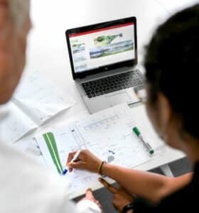


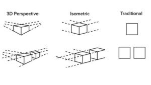


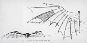
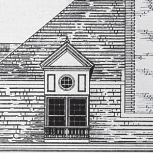
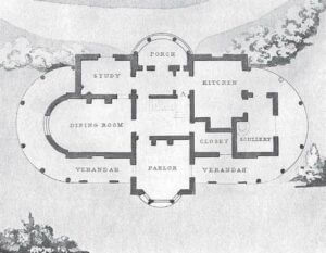 Many early
  Into the late 1800s and early 1900s, inventors, engineers, and builders worked on each product on a one-of-a-kind basis. Manufactures produced parts from hand sketches or hand drawings on blackboards. American engineer and inventor Coleman Sellers, in the manufacture of fire engines, had blackboards with full-size drawings of parts. Blacksmiths formed parts and compared them to the shapes on the blackboards. Coleman Sellers son, George Sellers, recalls lying on his belly using his arms as a radius for curves as his father stood over him direct-ing changes in the sketches until the drawings were satisfactory. Most designs used through the 1800s began as a hand sketches of the objects to be built. Workers then converted the sketches into wooden models from which patterns were constructed. Some companies followed this practice well into the twentieth century. An example is Henry Ford and his famous blackboards. What was new, though, was that the blackboards were also the Henry Ford drafting tables. Henry would sketch cars and parts three-dimensionally and have pattern makers construct full-size wooden models.
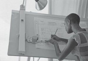 Drafters initially created drawings by hand on a drafting table referred to as aboard. An advance in drafting occurred with the introduction of the drafting machine, which replaced the T-square, triangles, scales and protractor for creating drawings. The drafting machine mounts to the table or board and has scales attached to an adjustable head that rotates for drawing angles. When locked in a zero position, the scales allow drawing horizontal and vertical lines and perpendicular lines at any angle orientation. There are arm and track drafting machines. The arm machine has arms attached to a mounting bracket at the top of the table. The arms control the movement of the head. The track machine has a traversing track that mounts to the table and a vertical track that moves along the horizontal track. The machine head traverses vertically on the track as shown in Figure.
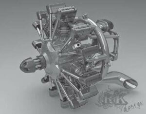 In the 1980s, schools started teaching CADD in their curricula by adding a few computers into the traditional manual drafting program. Eventually, half of the typical classroom was equipped with traditional drafting tables and the other half was CADD workstations, or the school would open a separate CADD lab to teach courses. This plan closely paralleled what was happening in the industry for those companies that were taking CADD seriously. By the 1990s, many schools and companies were starting to make the complete transition to CADD by replacing manual drafting tables with CADD workstations. Today, CADD accounts for almost all design and drafting. The figure shows a 3-D model of an aeroplane engine, which demonstrates the power of CADD for designing products.
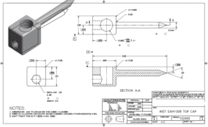
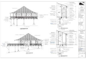

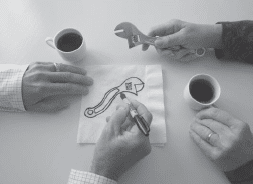
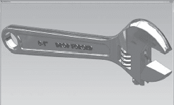
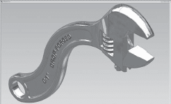
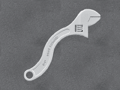 The figure shows the prototype of the new wrench design. The design team tests the prototype in an application similar to what the engineer experienced at home. The prototype worked as expected.
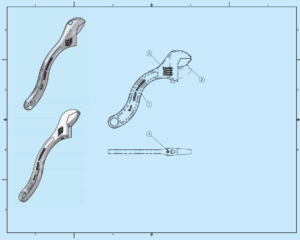 By the next afternoon, the drafter completes the set of working drawings shown in Figure and sends the drawings to the manufacturing department to manufacture and assemble the new product. The manufacturing department needs lead time to design and make the forging dies required to reproduce the parts. Lead time is the time interval between the initiation and the completion of a production process. Forging is the process of shaping malleable metals by hammering or pressing between dies that duplicate the desired shape. The hand-tool company is small, so the drafter is also responsible for creating catalogue art and copy for marketing the product.
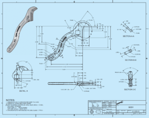 Assembly Drawings and Parts List & Detail drawing of the new wrench body part
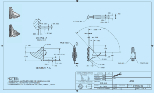 Detail drawing of the new wrench JAW part.
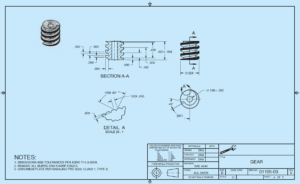 Detail drawing of the new wrench GEAR part.
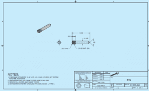 Detail drawing of the new wrench PIN part.
 Less than two months after the engineer had the initial idea, the first production run of new wrenches is ready to sell. The figure shows the finished product.