1800 287 223 · [email protected]
3D Mechanical Parts in AutoCAD

Designing 3D Mechanical Parts in AutoCAD is an essential skill for engineers, designers, and manufacturers who want to bring their ideas to life with precision and efficiency. AutoCAD, developed by Autodesk, is one of the most widely used CAD software applications for creating detailed mechanical drawings, models, and assemblies. Whether you’re designing machine components, tools, or industrial equipment, AutoCAD provides a robust platform to create accurate 3D models that streamline prototyping and manufacturing processes.

In this guide, we’ll walk through the basics of designing 3D Mechanical Parts in AutoCAD, share practical tips, and answer some frequently asked questions.


Why Use AutoCAD for 3D Mechanical Parts?

AutoCAD is not just for 2D drafting—it’s a powerful tool for 3D modelling as well. Here’s why it’s ideal for mechanical part design:

  • Precision and Accuracy: AutoCAD allows you to create models down to the finest detail, ensuring every hole, slot, and dimension aligns perfectly.
  • Compatibility: Files can be exported in various formats (e.g., .STL, .STEP, .IGES), making it easy to integrate with 3D printers, CNC machines, and other CAD/CAM software.
  • Visualisation: 3D models provide a realistic preview of mechanical parts, helping to detect design flaws before production.
  • Efficiency: The parametric and feature-based design tools allow for quick modifications, saving time in the design iteration process.

Steps to Design 3D Mechanical Parts in AutoCAD

1. Start with a Concept

Before diving into AutoCAD, have a clear idea of the part you want to design. Gather sketches, technical requirements, and measurements. This will help guide your 3D modelling process.

2. Set Up the AutoCAD Workspace

  • Switch to a 3D Modelling workspace by going to the workspace settings in AutoCAD.
  • Familiarize yourself with the 3D tools panel: Extrude, Revolve, Sweep, Loft, and Boolean operations (Union, Subtract, Intersect).

3. Create a 2D Sketch

Every 3D model starts with a 2D sketch:

  • Use commands like LINE, CIRCLE, RECTANGLE, and POLYLINE to draw the base profile of your part.
  • Ensure that dimensions are accurate using the DIMENSION tool.

4. Convert 2D Sketches into 3D Models

  • EXTRUDE: Turn a closed 2D profile into a 3D solid by pulling it along the Z-axis.
  • REVOLVE: Rotate a 2D sketch around an axis to create cylindrical or spherical parts (useful for gears, pulleys, or shafts).
  • SWEEP and LOFT: Create complex parts by sweeping a profile along a path or lofting between multiple shapes.

5. Modify 3D Models

Once you’ve created the basic shape, refine it with modification tools:

  • FILLET and CHAMFER: Add smooth edges or beveled corners.
  • SHELL: Hollow out parts to reduce weight.
  • BOOLEAN operations: Combine or subtract solids to create complex designs.

6. Add Details

Mechanical parts often require features like holes, threads, or slots. Use the following:

  • HOLE or CYLINDER tool for drilled holes.
  • ARRAY tool to create repetitive features like bolt patterns.
  • PRESSPULL tool to cut shapes into surfaces.

7. Apply Materials and Rendering

Assign materials (metal, plastic, etc.) to your part for realistic visualisation. AutoCAD’s rendering tools help you see how your design will look in real-world conditions.

8. Check and Export Your Design

  • Use MEASURE tools to verify dimensions.
  • Export in formats like .STL for 3D printing or .STEP/IGES for manufacturing.

Best Practices for Designing 3D Mechanical Parts in AutoCAD

  • Start Simple: Break down complex parts into smaller, simpler shapes before combining them.
  • Use Constraints: Apply geometric and dimensional constraints to maintain design accuracy.
  • Organise with Layers: Assign different parts or features to layers for easier editing.
  • Regularly Save Versions: Keep backups as you progress to avoid losing work.
  • Simulate Movements: If designing assemblies, test how parts move and fit together.

Common Applications of 3D Mechanical Parts in AutoCAD

  • Automotive components (gears, engine parts)
  • Industrial machinery and equipment
  • Aerospace components
  • Consumer products (electronics housings, tools, etc.)
  • Prototypes for 3D printing and CNC machining

Final Thoughts

Designing 3D Mechanical Parts in AutoCAD allows engineers and designers to create highly accurate and functional models that bridge the gap between concept and reality. By mastering the core 3D tools, understanding best practices, and practising regularly, you can unlock AutoCAD’s full potential in mechanical design.

Whether you are a beginner or a professional, AutoCAD equips you with the tools to design, visualise, and prepare your mechanical parts for real-world applications.

Can beginners design 3D Mechanical Parts in AutoCAD?

Yes! AutoCAD is beginner-friendly, and with practice, you can quickly learn to design simple parts before progressing to more complex mechanical assemblies.

What file format should I use for 3D printing mechanical parts?

For 3D printing mechanical parts, we recommend using .STL format as it’s widely supported by most Australian and international 3D printing services. However, if you’re sharing designs with manufacturers or need to preserve complex geometry, .STEP or .IGES formats are superior choices as they maintain full design intent. We suggest confirming your service provider’s preferred format before finalising your export.

How do I ensure accuracy in my 3D models?

We recommend enabling SNAP and GRID settings to maintain precision throughout your 3D modeling process, then apply geometric constraints during sketching to lock relationships between elements. Always verify dimensions against your design specifications and Australian standards before extruding or modifying features. Double-check measurements using the DIMENSION tools, and consider using our drafting templates that align with local engineering conventions to ensure your models meet project requirements.

Can AutoCAD simulate stress or load on mechanical parts?

AutoCAD itself doesn’t have built-in stress simulation, but as an Australian CAD drafting firm, we recommend exporting your models to Autodesk Inventor or Fusion 360 for comprehensive stress analysis and FEA testing. Many of our clients use these integrated tools for compliance with Australian engineering standards before manufacturing.

Is AutoCAD better than SolidWorks or Fusion 360 for mechanical design?

AutoCAD excels at 2D drafting and basic 3D modeling, making it ideal for many Australian engineering projects and construction documentation. However, SolidWorks and Fusion 360 offer superior parametric modeling, assembly capabilities, and simulation tools better suited for complex mechanical design. We recommend AutoCAD for detailed technical drawings and compliance with Australian Standards, while considering specialist software for advanced product development requiring extensive testing and iteration.

JH

James Hartley

Senior Mechanical Engineer · BEng (Mechanical), UQ · Member, Engineers Australia · ASTCAD, Brisbane

James has 14 years of hands-on experience delivering CAD design, structural drafting, and engineering documentation across Australia’s mining, oil & gas, and manufacturing sectors. He specialises in SolidWorks, Autodesk Inventor, and AutoCAD for complex multi-discipline projects.

More articles by James Hartley →
Engineering Drawings in AutoCAD

Creating precise and professional engineering drawings in AutoCAD is a fundamental skill for engineers, architects, and designers. AutoCAD has become the industry standard software for technical drafting, allowing professionals to transform concepts into detailed 2D and 3D drawings. Whether you’re a beginner or someone looking to refine your drafting skills, learning how to prepare engineering drawings in AutoCAD step by step will give you a strong foundation.

In this guide, we’ll cover the process of creating engineering drawings in AutoCAD, along with essential tips to help you get started.


What Are Engineering Drawings in AutoCAD?

Engineering drawings are technical representations that communicate design ideas clearly and accurately. These drawings serve as blueprints for manufacturing, construction, or product development. AutoCAD simplifies this process by offering tools for precision, scaling, annotations, and dimensioning, ensuring that the drawings meet industry standards.

With AutoCAD, beginners can create mechanical parts, architectural floor plans, structural layouts, and electrical schematics with ease.


Step-by-Step Guide: How to Create Engineering Drawings in AutoCAD

Step 1: Launch AutoCAD and Set Up the Workspace

  • Open AutoCAD and select a new drawing file.
  • Configure the drawing units (millimetres, centimetres, or inches) using the UNITS command.
  • Set up the drawing limits with the LIMITS command to define your workspace.

This ensures that your engineering drawing is created with the right scale and measurement system from the beginning.


Step 2: Create Layers

Layers help organise different components of your drawing. For example, walls, dimensions, annotations, and centerlines can each have separate layers.

  • Use the LAYER command to create and manage layers.
  • Assign colours and line types for better readability.

Organised layers make your drawing professional and easy to interpret.


Step 3: Start with Basic Geometry

  • Use commands like LINE, CIRCLE, RECTANGLE, and POLYGON to create the basic shapes.
  • Snap and grid settings ensure accuracy by locking points to intersections or midpoints.
  • The OSNAP feature is particularly useful for precision.

This step forms the skeleton of your engineering drawing.


Step 4: Add Dimensions and Annotations

Dimensions are critical in engineering drawings. They define sizes, distances, and tolerances.

  • Use the DIMLINEAR, DIMANGULAR, and DIMALIGNED commands for different types of dimensions.
  • Add text using the TEXT or MTEXT command for notes, labels, and instructions.

This ensures that your drawing communicates technical details effectively.


Step 5: Apply Hatching and Section Views

  • Use the HATCH command to apply patterns to cross-sections, helping to identify materials or cut areas.
  • Section views can be created to show internal features of objects, especially in mechanical drawings.

This makes the drawing more informative and professional.


Step 6: Insert Title Block and Border

Every engineering drawing needs a title block that includes information such as:

  • Project name
  • Designer’s name
  • Date
  • Scale
  • Revision number

AutoCAD allows you to create custom title blocks or use pre-defined templates.


Step 7: Final Checks and Plotting

  • Verify layers, scales, and dimensions.
  • Use the AUDIT and PURGE commands to clean up unused items.
  • Plot or print your drawing using the PLOT command, ensuring that line weights and scales are correct.

Your engineering drawing is now ready for professional use.


Tips for Beginners in AutoCAD Engineering Drawings

  1. Practice with simple projects like bolts, floor plans, or brackets before moving to complex designs.
  2. Use keyboard shortcuts to speed up your drafting process.
  3. Save versions of your file frequently to avoid losing progress.
  4. Refer to drafting standards (ISO, ANSI, or BIS) to make your drawings universally acceptable.
  5. Leverage AutoCAD tutorials and templates to learn industry-specific drawing techniques.

Why Use AutoCAD for Engineering Drawings?

  • Accuracy: AutoCAD allows exact measurements, which is crucial in engineering.
  • Efficiency: Reusable blocks, layers, and templates speed up drawing creation.
  • Collaboration: DWG files can be shared easily across industries.
  • 3D Capabilities: Beginners can start with 2D drawings and gradually move into 3D modelling.

Conclusion

Learning how to create engineering drawings in AutoCAD is a crucial step for anyone entering the engineering or design field. By following a structured process—setting units, creating layers, drafting geometry, adding dimensions, and finalising with title blocks—you can produce professional-grade drawings. With practice and attention to detail, beginners can master AutoCAD and unlock opportunities in various technical industries.

Is AutoCAD difficult for beginners?

AutoCAD may seem overwhelming at first, but with consistent practice and step-by-step learning, beginners can create professional engineering drawings within weeks. At ASTCAD, we’ve helped countless Australian engineers and drafters master the fundamentals, and we find that most of our clients are confidently producing compliant drawings for Australian Standards within their first month. We recommend starting with basic 2D drafting tasks before moving to 3D modeling, and our team is always available to guide you through the learning process with practical, real-world examples specific to Australian construction and engineering requirements.

Do I need to know engineering concepts before using AutoCAD?

While basic engineering knowledge is helpful, you don’t need to be an expert to start with AutoCAD. At ASTCAD, we recommend familiarising yourself with Australian Standards like AS 1100 for technical drawing conventions, which will help you create compliant and professional drawings. AutoCAD is ultimately a tool for translating your ideas into precise drawings, so pairing it with fundamental understanding of drafting principles ensures your work meets industry requirements and communicates clearly with other professionals.

Can I use AutoCAD for both 2D and 3D drawings?

Yes. AutoCAD is versatile and supports both 2D drafting and 3D modeling, making it ideal for engineering applications.

How do I learn shortcuts in AutoCAD?

Start with commonly used commands like L (Line), C (Circle), TR (Trim), and CO (Copy) to build your foundation. We recommend practicing these daily until they become second nature, then gradually adding more advanced shortcuts. At ASTCAD, we’ve found that Australian engineers benefit from learning industry-specific shortcuts relevant to local standards and compliance requirements. Consistent practice and customizing your keyboard shortcuts to match your workflow will significantly boost your productivity in AutoCAD.

Which industries use engineering drawings in AutoCAD?

Engineering drawings in AutoCAD are essential across mechanical, civil, electrical, architectural, and manufacturing sectors. We at ASTCAD see Australian businesses in these industries rely on AutoCAD for precise technical documentation that meets local standards and compliance requirements. Whether you’re designing infrastructure for Australian construction projects or creating manufacturing specifications, our team helps ensure your drawings are accurate and industry-compliant from start to finish.


JH

James Hartley

Senior Mechanical Engineer · BEng (Mechanical), UQ · Member, Engineers Australia · ASTCAD, Brisbane

James has 14 years of hands-on experience delivering CAD design, structural drafting, and engineering documentation across Australia’s mining, oil & gas, and manufacturing sectors. He specialises in SolidWorks, Autodesk Inventor, and AutoCAD for complex multi-discipline projects.

More articles by James Hartley →
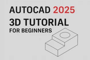
AutoCAD 2025 3D Tutorial for Beginners || AutoCAD 2D to 3D Convert || Step by Step

AutoCAD has always been a powerful tool for engineers, architects, and designers who want to bring their ideas to life. With the release of AutoCAD 2025, creating precise 2D drawings and converting them into 3D models has become even more intuitive. For beginners, learning the step-by-step process of AutoCAD 2D to 3D convert can be a game-changer, helping you visualise projects better and communicate ideas more effectively.

In this tutorial, we’ll walk through the basics of using AutoCAD 2025 to create 3D models from 2D drawings, along with tips to make the transition smoother for new users.


Why Move from 2D to 3D in AutoCAD?

While 2D drafting is essential for floor plans, schematics, and technical layouts, 3D modelling adds depth and realism to your designs. The benefits of converting 2D to 3D in AutoCAD include:

  • Improved visualisation – 3D models provide a realistic view of how the final product will look.
  • Better communication – Clients and stakeholders understand 3D visuals more easily than 2D lines.
  • Reduced errors – Spot design issues early by rotating and examining models from different angles.
  • Efficient workflows – Switching to 3D reduces rework and simplifies design modifications.

Getting Started with AutoCAD 2025

Before diving into AutoCAD 2D to 3D convert, make sure you:

  1. Have AutoCAD 2025 installed and updated.
  2. Switch to the 3D Modelling Workspace (found in the top-right corner of AutoCAD).
  3. Familiarize yourself with the 3D tools like Extrude, Revolve, PressPull, and Union.

Step-by-Step Guide: AutoCAD 2D to 3D Convert

Here’s a simple workflow beginners can follow to turn a 2D drawing into a 3D model:

Step 1: Start with a Clean 2D Drawing

  • Open your 2D plan in AutoCAD 2025.
  • Ensure all lines are connected (use the Join command if necessary).
  • Organise layers so each element is easy to identify.

Step 2: Switch to 3D Workspace

  • Go to the top-right corner and select 3D Modelling workspace.
  • The ribbon will update with 3D tools.

Step 3: Create Regions or Surfaces

  • Use the REGION command to convert closed 2D shapes into regions.
  • These regions can then be extruded into 3D solids.

Step 4: Use the Extrude Command

  • Select a closed shape and type EXTRUDE.
  • Enter a height value to give the object thickness.
  • Example: extruding a rectangle into a 3D wall.

Step 5: Apply Revolve for Circular Objects

  • For round objects (like pipes or cylinders), draw a profile in 2D.
  • Use the REVOLVE command around an axis to create 3D geometry.

Step 6: Modify and Refine

  • Use PressPull to push/pull surfaces.
  • Use Union, Subtract, and Intersect to combine or cut objects.
  • Apply Materials and Visual Styles for realistic effects.

Tips for Beginners in AutoCAD 2025 3D

  • Practice simple models first – Start with cubes, cylinders, and basic shapes.
  • Learn shortcuts – Commands like EXTRUDE (EXT), PRESSPULL, and REVOLVE save time.
  • Use isometric view – Switch views frequently (Top, Front, Isometric) to understand geometry.
  • Save regularly – Large 3D models can slow down your system, so save your work often.
  • Experiment with rendering – AutoCAD 2025 has improved rendering for better presentations.

Applications of AutoCAD 2D to 3D Convert

  • Architecture – Transform 2D floor plans into realistic building models.
  • Mechanical engineering – Convert component sketches into machine parts.
  • Interior design – Visualise furniture, layouts, and space planning.
  • Civil engineering – Create 3D bridges, roads, and site layouts.

Conclusion

Mastering AutoCAD 2D to 3D convert in AutoCAD 2025 is an essential step for beginners who want to elevate their design skills. By learning how to extrude, revolve, and modify 3D shapes, you can transform simple 2D drawings into realistic 3D models. Whether you’re an architect, engineer, or student, practising these tools will help you visualise and communicate your ideas effectively.

With AutoCAD 2025, the process has become more user-friendly, making it the perfect time for beginners to dive into 3D modelling.

Is AutoCAD 2025 beginner-friendly for 3D modeling?

Yes, AutoCAD 2025 is very beginner-friendly for 3D modeling. We’ve found the simplified interface and guided workflows make it easy for Australian drafters to transition from 2D to 3D work. Our step-by-step tutorials help you master 3D modeling quickly, and the software supports Australian design standards and conventions used across construction and engineering industries.

What’s the difference between 2D and 3D in AutoCAD?

In AutoCAD, 2D drawings use only X and Y coordinates for flat plans commonly used in Australian architectural and construction documentation. 3D adds the Z-axis for depth, enabling realistic models essential for visualising building projects, engineering designs, and complex structures before construction begins. We recommend starting with 2D fundamentals before progressing to 3D modelling for comprehensive design solutions.

Can I convert old 2D drawings into 3D in AutoCAD 2025?

Absolutely. At ASTCAD, we help Australian drafters convert legacy 2D drawings into 3D models using AutoCAD 2025. Simply open your existing files, clean up the geometry, then use commands like EXTRUDE and REVOLVE to build 3D solids. We recommend validating dimensions against your original specifications before finalising your 3D conversion.

Do I need a powerful computer for AutoCAD 3D?

For basic 3D modeling in AutoCAD, most modern PCs work fine. However, for larger and more complex models typical in Australian architectural and engineering projects, we recommend a system with at least 16GB RAM, a dedicated graphics card, and SSD storage. We find that professionals working on construction documentation and detailed technical drawings benefit significantly from these specifications to ensure smooth performance and faster rendering times.

How can I learn AutoCAD 2D to 3D convert faster?

Start with simple exercises, watch beginner tutorials, and practice regularly. At ASTCAD, we recommend our step-by-step guidelines that focus on Australian building standards and construction practices. AutoCAD 2025’s built-in learning resources, combined with our specialised 3D conversion techniques, help you master the transition from 2D to 3D drafting faster.


CS

Claire Sutton

Architectural CAD Specialist & Technical Writer · BArch (Hons), QUT · ASTCAD, Brisbane

Claire has 10 years of experience in Revit BIM modelling, architectural documentation, and CAD conversion projects across Southeast Queensland and NSW. She has delivered NCC-compliant documentation for residential, commercial, and industrial facilities.

More articles by Claire Sutton →
PDF Drawings to DWG File in AutoCAD

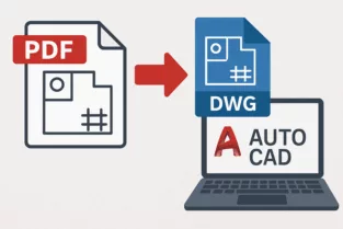
In the world of design, engineering, and construction, sharing drawings in PDF format is common practice. However, professionals often need to edit these drawings in AutoCAD, which requires converting them into DWG files. If you’ve ever wondered how to efficiently convert PDF Drawings to DWG File in AutoCAD, this guide will walk you through the process step by step. By the end, you’ll have a clear understanding of how to handle PDF conversions and make your workflow smoother.


Why Convert PDF Drawings to DWG File in AutoCAD?

PDFs are excellent for sharing and printing drawings because they maintain formatting across different devices. However, PDFs are not editable in their native form. On the other hand, DWG files—the native format for AutoCAD—allow full editing capabilities. Converting PDF to DWG files in AutoCAD ensures you can:

  • Edit lines, curves, and shapes directly.
  • Modify text, dimensions, and annotations.
  • Incorporate old project drawings into new designs.
  • Save time by avoiding manual redrawing.

Step-by-Step Guide to Converting PDF to DWG in AutoCAD

Here’s a simple, detailed process to help you convert files accurately.

Step 1: Open AutoCAD

Start by launching AutoCAD on your computer. Ensure you’re using a version that supports PDF import functionality (AutoCAD 2017 and later versions include this feature).

Step 2: Locate the PDF Import Tool

  • Go to the Insert tab on the AutoCAD ribbon.
  • Select the Import PDF option.

Step 3: Choose Your PDF File

A file selection window will appear. Browse and select the PDF drawing you want to convert. AutoCAD allows both single-page and multi-page PDFs to be imported.

Step 4: Adjust Import Settings

AutoCAD will display several import options:

  • Specify Insertion Point, Scale, and Rotation – Allows you to control where and how the PDF is placed.
  • Import PDF Data – Choose whether to import geometry, text, or raster images.
  • Layers – You can decide whether to import objects to one layer or retain original PDF layer settings.

Choose the settings according to your project needs.

Step 5: Complete the Import

Click OK to finalise the import. AutoCAD will convert the PDF elements into editable DWG objects, such as polylines, arcs, and text.

Step 6: Clean Up the Drawing

After conversion, some elements may need adjustments. For example:

  • Text might not align perfectly.
  • Hatch patterns may appear as separate lines.
  • Raster images remain as non-editable objects.

Use AutoCAD’s editing tools to refine the drawing for better accuracy.


Best Practices for Converting PDF to DWG in AutoCAD

To ensure smooth conversions, consider these tips:

  • Use High-Quality PDFs: Low-resolution or scanned PDFs may result in inaccurate DWG conversions.
  • Simplify Before Importing: If possible, reduce the number of layers or details in the original PDF.
  • Check for Scaling Issues: Always verify dimensions after importing to maintain accuracy.
  • Clean Unnecessary Objects: Delete extra lines, duplicate text, or unwanted raster images after conversion.

Benefits of Using AutoCAD’s Built-In PDF to DWG Conversion

  1. Time-Saving: No need for manual tracing of drawings.
  2. Accuracy: Vector data from PDFs is directly converted into editable geometry.
  3. Compatibility: Imported files can be integrated into new or ongoing projects.
  4. Cost-Effective: Eliminates the need for third-party conversion software.

Common Challenges and How to Overcome Them

  • Scanned PDFs: AutoCAD cannot directly convert raster images into editable geometry. In such cases, use OCR (Optical Character Recognition) software before importing.
  • Text Recognition Issues: Sometimes, text may import as polylines instead of editable text. Use AutoCAD’s TXTEXP or manually replace the text.
  • File Size: Large PDFs can slow down AutoCAD. Simplify or break down the file if necessary.

Conclusion

Converting PDF to DWG in AutoCAD is a powerful way to reuse existing drawings without wasting time on manual redrawing. By following the step-by-step guide above, you can import PDFs directly, edit them as needed, and integrate them into your projects with ease. Although you may need to refine the file after import, the process ultimately saves time, boosts productivity, and ensures higher accuracy in your design workflow.

If you often work with shared drawings, mastering PDF to DWG conversion in AutoCAD is an essential skill that enhances efficiency and collaboration across projects.

Can AutoCAD convert scanned PDF drawings to DWG?

AutoCAD’s import tool works best with vector-based PDFs, which is common for most professional drawings in Australia. For scanned or raster PDFs, we recommend using OCR software to convert the image data, or our team can assist with manual tracing for complex architectural and engineering documents. We find this approach ensures accuracy for Australian building codes and standards compliance.

Is the converted DWG file 100% accurate?

Not always, but our experience with Australian construction standards shows AutoCAD handles most conversions well. You may need to clean up lines, text, and hatches after import, especially if your original PDF contains complex hatching or non-standard fonts common in older Australian plans. We recommend reviewing layers and scale references to ensure compliance with local building codes before finalising your DWG file.

Which versions of AutoCAD support PDF to DWG conversion?

AutoCAD 2017 and later versions include a built-in PDF import tool that makes conversion straightforward. If you’re using older versions, we recommend third-party solutions like Adobe Acrobat or dedicated conversion software. Here at ASTCAD, we typically advise Australian firms to upgrade to current versions, as they offer better compatibility with local standards and improved performance for complex technical drawings.

Can I batch convert multiple PDFs to DWG files?

Yes, while AutoCAD doesn’t have native batch conversion features, we recommend using third-party conversion tools like Able2Extract or specialist PDF-to-DWG converters for processing multiple files efficiently. Many Australian engineering firms use these solutions to handle large document batches, which saves considerable time on projects. We can advise on reliable options during your consultation if you’re managing extensive drawing conversions for your practice.

Do I lose any data during conversion?

Raster images and some special annotations may not convert to editable objects. Always review the file after import to ensure accuracy


CS

Claire Sutton

Architectural CAD Specialist & Technical Writer · BArch (Hons), QUT · ASTCAD, Brisbane

Claire has 10 years of experience in Revit BIM modelling, architectural documentation, and CAD conversion projects across Southeast Queensland and NSW. She has delivered NCC-compliant documentation for residential, commercial, and industrial facilities.

More articles by Claire Sutton →
AI for 2D Drafting & Drawing

In the world of architectural, mechanical, and civil design, 2D drafting remains a foundational element of any successful project. But with increasing pressure to deliver high-quality drawings faster and with greater accuracy, professionals are now turning to AI for Automated 2D Drafting & Drawingto streamline workflows, minimise errors, and increase productivity.

AI for Automated 2D Drafting & Drawing

AI technologies are revolutionizing traditional CAD processes, automating repetitive tasks, and intelligently suggesting or even generating complete design elements. If you’re looking to integrate AI into your drafting process, this step-by-step guide will walk you through the essential stages.


Step 1: Understand the Capabilities of AI in 2D Drafting

Before diving into automation, it’s important to understand what AI can do in the context of 2D drafting and drawing:

  • Auto-generation of floor plans and layouts based on parameters.
  • Intelligent object recognition and annotation.
  • Real-time error detection and correction.
  • Layer management and standardisation.
  • Drafting suggestions based on learned design patterns.

AI tools don’t replace designers—they enhance their capabilities by taking over time-consuming tasks, allowing engineers and architects to focus on creativity and precision.


Step 2: Choose the Right AI-Powered Drafting Software

To get started with AI for 2D Drafting & Drawing, you need software that integrates AI-driven features. Some popular tools include:

  • AutoCAD with Autodesk AI enhancements
  • BricsCAD with AI-assisted BIM and drafting tools
  • ZWCAD with smart voice and drawing commands
  • ArCADia BIM for architecture-focused automation

Ensure the software supports your file formats, industry standards, and offers integration with existing tools in your workflow.


Step 3: Train or Upload Existing Drawing Data

AI becomes more effective when it has access to a rich dataset. Most platforms allow you to upload previous drawings or standard templates so the AI can:

  • Learn recurring patterns.
  • Understand layer usage.
  • Automate recurring annotations or dimensioning styles.

Feeding your system with historical data increases the relevance and accuracy of the automated suggestions.


Step 4: Set Automation Parameters

Depending on your project type, you can set rules or parameters for:

  • Dimensions and tolerances.
  • Layer styles and naming conventions.
  • Text annotations and callouts.
  • Symbol libraries and object standards.

This ensures AI-generated drawings adhere to your firm’s standards or specific project requirements.


Step 5: Automate Repetitive Drafting Tasks

Once your AI system is trained and set up, you can begin automating:

  • Title block insertion and sheet numbering.
  • Layer assignment and visibility control.
  • Auto-dimensioning of standard components.
  • Repetitive component placement (e.g., windows, beams, fixtures).

This saves hours on tasks that were once manually done, especially in large projects.


Step 6: Use AI-Based Error Detection

One of the most powerful applications of AI for 2D Drafting & Drawing is error detection. AI can:

  • Identify misaligned objects.
  • Detect missing dimensions or annotations.
  • Flag inconsistencies in layer usage.
  • Highlight overlaps or potential conflicts.

This real-time feedback dramatically reduces costly revisions and improves drawing quality.


Step 7: Collaborate and Review

Many AI-powered drafting platforms include cloud or team-based review features. Use these to:

  • Share AI-generated drafts for feedback.
  • Track design suggestions and corrections.
  • Collaborate with remote teams and make decisions faster.

AI can also assist during this stage by summarizing changes or tracking revision history.


Step 8: Export and Finalise Your Drawings

After review, AI tools allow you to finalise and export your work into:

  • DWG/DXF files for CAD platforms.
  • PDF for client sharing.
  • BIM formats for integration with 3D models.

Make sure to do a manual check of all automated tasks before final submission, especially for regulatory compliance or project approvals.


Benefits of Using AI for 2D Drafting & Drawing

  • Speed: Automates hours of manual work.
  • Accuracy: Reduces human error.
  • Consistency: Ensures all drawings follow standards.
  • Productivity: Teams can complete more work in less time.
  • Innovation: Allows designers to focus on high-level tasks.

AI is transforming the way we approach drafting by simplifying processes, improving accuracy, and helping professionals focus on design excellence. By following this step-by-step guide, you can start incorporating AI for 2D Drafting & Drawing in your workflow and stay ahead in an increasingly automated industry.

Can AI completely replace human drafters in 2D drawing tasks?

AI enhances and supports human capabilities but does not replace the critical thinking, creativity, and decision-making that human designers bring to the table.

What type of projects benefit the most from AI in 2D drafting?

Projects with repetitive tasks, high volumes of drawings, or standard design elements (like housing layouts, piping schematics, electrical plans) benefit greatly from AI-based automation.

Is it necessary to have programming knowledge to use AI drafting tools?

No, programming knowledge isn’t necessary to use our AI drafting tools at ASTCAD. Our platform is designed with Australian drafting professionals in mind, featuring intuitive interfaces that automate common 2D tasks like line work, dimensioning, and standard detail generation without any coding required. For advanced users who want deeper customization, we do offer scripting options and API access, but these are entirely optional extensions to the core functionality.

Are AI drafting tools expensive?

AI drafting tools are increasingly affordable in Australia. Many mainstream CAD packages now include AI features as standard, while specialist tools are available as cost-effective add-ons. We recommend evaluating the productivity gains and time savings against the investment, as most Australian firms see positive ROI within months through faster project completion and reduced manual drafting hours.

Is AI drafting only useful for large firms?

No. Small and mid-size Australian drafting firms can benefit significantly from AI automation, often more than larger organisations. By streamlining repetitive 2D drafting tasks, you’ll reduce staff workload, accelerate project turnaround, and compete effectively against bigger competitors without proportional cost increases. Our AI tools are designed to scale with your business needs.


JH

James Hartley

Senior Mechanical Engineer · BEng (Mechanical), UQ · Member, Engineers Australia · ASTCAD, Brisbane

James has 14 years of hands-on experience delivering CAD design, structural drafting, and engineering documentation across Australia’s mining, oil & gas, and manufacturing sectors. He specialises in SolidWorks, Autodesk Inventor, and AutoCAD for complex multi-discipline projects.

More articles by James Hartley →
Convert MCD to DWG

In the world of architecture, engineering, and design, compatibility between file formats is essential. If you’ve ever worked with Vectorworks, you might have encountered files with the .mcd extension. However, most professionals working in AutoCAD prefer .dwg format due to its widespread compatibility. This blog provides a comprehensive step-by-step guide on how to convert MCD to DWG efficiently.

What is an MCD File?

MCD stands for MiniCAD Drawing, a file format used by older versions of Vectorworks (previously MiniCAD). These files contain design data, drawings, and 2D/3D objects used in architecture and engineering drafting. However, the MCD format is now outdated and has been replaced by the .vwx format in newer Vectorworks versions.

Why Convert MCD to DWG?

AutoCAD and many other CAD software programs use the DWG (Drawing) format, making it a standard for sharing design files. Converting your MCD file to DWG ensures:

  • Greater software compatibility
  • Easier collaboration with teams using AutoCAD
  • Simplified project management and archival
  • Access to more editing and annotation tools

How to Convert MCD File to DWG File – Step-by-Step

Follow these detailed steps to convert an MCD file to DWG format successfully:


Step 1: Check the Source Software

To convert MCD files, you will need access to Vectorworks—preferably the version that supports MCD files. If your file is from an older version, you may need to install an older version of Vectorworks first to open the file.

  • If you have a .mcd file, try using Vectorworks 2008 or earlier.
  • Open the MCD file within Vectorworks to confirm the content loads correctly.

Step 2: Save or Export as VWX (Optional but Recommended)

If you’re using a very old Vectorworks version:

  • First, save the MCD file as a VWX file, the newer format supported by recent Vectorworks versions.
  • This will help avoid compatibility issues in the next step.

Step 3: Use Vectorworks to Export as DWG

Vectorworks has a built-in export feature to convert files to AutoCAD DWG format.

To export the file:

  1. Open the MCD (or VWX) file in Vectorworks.
  2. Click on File > Export > Export DXF/DWG.
  3. A dialogue box will appear—choose the correct AutoCAD version (e.g., 2013, 2018, or 2021).
  4. Choose the layers, classes, or sheets you want to export.
  5. Click OK to begin the conversion.
  6. Vectorworks will generate a .dwg file that you can now open in AutoCAD.

Step 4: Verify the DWG Output in AutoCAD

Once the file is exported:

  1. Open AutoCAD.
  2. Go to File > Open and select your converted DWG file.
  3. Review the file for accuracy—check dimensions, layers, text, and geometry to ensure everything is intact.
  4. Make any necessary adjustments or layer reassignments within AutoCAD.

Alternative Method: Use File Conversion Software

If you don’t have access to Vectorworks, you can try using third-party file conversion tools or services. Some tools that claim to support MCD to DWG conversion include:

  • AnyConv
  • Zamzar
  • CloudConvert (limited success)
  • Professional CAD conversion services

Note: These tools often have limitations and may not support complex geometry or layer formatting, so use them only if the file is simple or if you have no other option.


Tips for Successful Conversion

  • Backup your original MCD file before conversion.
  • Use the latest compatible version of Vectorworks for better export options.
  • Maintain consistent units (mm/inches) during the export process.
  • Check layer visibility and class settings before exporting to DWG.

Common Issues and Fixes

IssueSolution
File not opening in VectorworksTry using an older version of Vectorworks or contact the file provider.
Exported DWG missing elementsEnable all layers/classes before exporting.
Text or dimensions look offRecheck font compatibility and dimension scale settings.
AutoCAD reports file errorUse DWG TrueView to check and recover corrupted files.

Being able to convert MCD file to DWG file is crucial for professionals dealing with legacy Vectorworks designs and modern AutoCAD workflows. Whether you’re using built-in Vectorworks export features or third-party conversion tools, following this guide ensures accurate and efficient results. Always verify the converted file for formatting, accuracy, and completeness to avoid issues during project development.

What software do I need to convert an MCD file to DWG?

To convert an MCD file to DWG format, you’ll need Vectorworks software, preferably version 2008 or earlier. We recommend this version because it offers the most reliable MCD compatibility and export functionality for Australian drafting standards. Once you have the file open in Vectorworks, you can simply export it as a DWG file, which is compatible with AutoCAD and most other industry-standard design programs used across Australian engineering and construction firms.

Can AutoCAD open MCD files directly?

No, AutoCAD cannot open MCD files directly as it doesn’t support this format. We recommend converting your MCD file to DWG using Vectorworks or a specialised converter tool before opening it in AutoCAD. This is particularly important for Australian projects where DWG remains the industry standard for compliance with local design standards and building codes. Our team can assist with conversion if needed.

Is there any free way to convert MCD files to DWG?

There is no fully free method unless you already have access to Vectorworks. Some online tools claim support, but reliability is not guaranteed.

Will the DWG file retain layers and line weights from the MCD file?

Yes, the DWG file will retain layers and line weights from your MCD file when you configure the export settings correctly in Vectorworks. We recommend checking that your layer names comply with Australian standards and that line weights are set to match your organisation’s drafting conventions before exporting. Our team can assist with specific configuration questions to ensure your converted files meet local engineering requirements.

What if I don’t have Vectorworks installed?

If you don’t have Vectorworks installed, we recommend contacting a professional CAD conversion service like ASTCAD to handle the conversion for you. Our team can quickly convert your MCD files to DWG format, ensuring compatibility with AutoCAD and other standard Australian drafting software. This is particularly useful if you’re collaborating with contractors or consultants who require DWG files for construction documentation or compliance with local building standards.


CS

Claire Sutton

Architectural CAD Specialist & Technical Writer · BArch (Hons), QUT · ASTCAD, Brisbane

Claire has 10 years of experience in Revit BIM modelling, architectural documentation, and CAD conversion projects across Southeast Queensland and NSW. She has delivered NCC-compliant documentation for residential, commercial, and industrial facilities.

More articles by Claire Sutton →
Mechanical Design

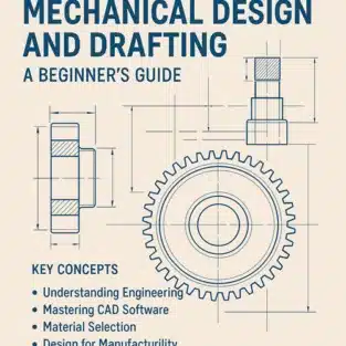
Mechanical design and drafting form the backbone of modern engineering. From the smallest machine components to large-scale industrial equipment, everything begins with a detailed design. If you’re new to the field, diving into mechanical design and drafting might seem overwhelming. But don’t worry—this beginner’s guide will simplify the process and help you build a strong foundation.

What is Mechanical Design and Drafting?

Mechanical design is the process of creating drawings and specifications for mechanical systems and components. It involves understanding how machines function, selecting suitable materials, and optimising the design for performance and cost.

Mechanical drafting, on the other hand, is the act of translating these design ideas into technical drawings using CAD (Computer-Aided Design) tools. These drawings include precise dimensions, tolerances, materials, and assembly instructions.

Together, mechanical design and drafting ensure that a product can be built accurately, efficiently, and safely.


Key Concepts for Beginners

1. Understanding Engineering Drawings

Engineering drawings are the universal language of engineers. They include multiple views (top, front, side), detailed dimensions, and annotations to communicate how a part or assembly should be built.

Familiarize yourself with:

  • Orthographic projection
  • Isometric views
  • Sectional views
  • Tolerances and GD&T (Geometric Dimensioning and Tolerancing)

2. Mastering CAD Software

CAD software is essential for drafting and designing. Popular tools include:

  • AutoCAD
  • SolidWorks
  • CATIA
  • Fusion 360
  • Siemens NX

Start with 2D drafting before transitioning into 3D modelling. Many software providers offer free student versions, which are perfect for beginners.

3. Material Selection

Understanding material properties is crucial in mechanical design. Factors like strength, weight, corrosion resistance, and cost influence material choices. Common materials include:

  • Steel
  • Aluminium
  • Brass
  • Plastics (ABS, Nylon, etc.)

4. Design for Manufacturability (DFM)

A good design isn’t just functional—it’s also easy and cost-effective to manufacture. DFM principles help avoid over-engineering and reduce production costs. Consider:

  • Minimising part complexity
  • Standardising components
  • Reducing the number of parts in an assembly

5. Working with Tolerances

Every manufactured part has some variation. Tolerances define the allowable limits. For instance, a shaft may be designed to be 20mm ± 0.02mm in diameter. Understanding tolerances is essential to ensure parts fit and function correctly.


Tips for Getting Started

  • Start Simple: Begin with basic projects like brackets, bushings, or gears to understand shapes and features.
  • Practice Regularly: Like any skill, drafting improves with practice. Try to replicate existing parts to sharpen your understanding.
  • Learn from Others: Study professional drawings, join online communities, and watch tutorials.
  • Understand Industry Standards: Familiarize yourself with ANSI, ISO, and other relevant drafting standards.

Common Mistakes to Avoid

  1. Skipping the Planning Phase: Always sketch and plan your design before jumping into CAD.
  2. Neglecting Tolerances: Ignoring tolerances can lead to assembly failures.
  3. Overcomplicating Designs: Keep your designs simple and functional.
  4. Not Backing Up Files: Always save and back up your design files to avoid data loss.
  5. Ignoring Manufacturing Constraints: Design with the end process (machining, 3D printing, etc.) in mind.

Tools and Resources

  • Books: “Technical Drawing with Engineering Graphics” by Frederick Giesecke, and “Machine Design” by Khurmi & Gupta.
  • Courses: Free CAD tutorials on platforms like Coursera, Udemy, and YouTube.
  • Communities: Reddit’s r/engineering, GrabCAD, and Autodesk forums.

Mechanical design and drafting are essential skills in today’s engineering and manufacturing industries. By starting with the basics and gradually building your knowledge and portfolio, you’ll be well on your way to a rewarding career in design. Whether you’re aiming to become a product designer, mechanical engineer, or CAD technician, this foundational knowledge is your first step to success.

What is the difference between 2D drafting and 3D modeling?

2D drafting creates flat technical drawings showing top, front, and side views, which is ideal for construction documentation and manufacturing specifications commonly used across Australian building codes. 3D modeling builds complete digital objects in three dimensions, letting you visualize designs better and run simulations before production. We recommend starting with 2D for traditional drawings, then progressing to 3D when you need to present designs to clients or test fit and function.

Is coding required for mechanical design?

No, coding isn’t required for mechanical design with ASTCAD. Our software uses intuitive graphical tools that Australian engineers and drafters rely on daily for creating precise technical drawings and 3D models. However, if you’re interested in automating repetitive tasks or running simulations, basic programming knowledge in Python can be beneficial. Most users successfully complete projects without any coding experience at all.

How long does it take to learn mechanical drafting?

With consistent practice, you can grasp basic 2D drafting in a few weeks, though mastering our software’s Australian-specific features like compliance with AS/NZS standards may take a little longer. 3D modeling and advanced mechanical concepts typically require a few months of dedicated learning. We recommend our structured tutorials and practical projects to accelerate your progress, and many of our Australian clients find they’re productive within their first month.

Can I learn mechanical drafting online?

Yes, absolutely! We offer online mechanical drafting courses and resources designed specifically for Australian standards and practices. Our beginner-friendly tutorials cover everything from AutoCAD basics to AS/NZS compliance requirements, so you can learn at your own pace from anywhere in Australia. Many of our clients have successfully transitioned to professional roles using our online training platform combined with practical exercises.

Do I need a degree to become a mechanical designer?

While a degree helps, many successful designers come from diploma or certification backgrounds. What matters most is your skill, portfolio, and understanding of design principles.


JH

James Hartley

Senior Mechanical Engineer · BEng (Mechanical), UQ · Member, Engineers Australia · ASTCAD, Brisbane

James has 14 years of hands-on experience delivering CAD design, structural drafting, and engineering documentation across Australia’s mining, oil & gas, and manufacturing sectors. He specialises in SolidWorks, Autodesk Inventor, and AutoCAD for complex multi-discipline projects.

More articles by James Hartley →
Sheet Metal Design

Sheet metal design is a vital skill in mechanical and industrial engineering, enabling the creation of durable and functional parts used in products ranging from electronics to automotive and aerospace systems. For CAD beginners, understanding how to approach sheet metal design for fabrication can make the difference between a concept that works in theory and one that performs reliably in the real world.

In this tutorial, we’ll walk you through the key steps of designing for sheet metal fabrication using CAD tools. We’ll also provide helpful tips to avoid common pitfalls and ensure your designs are both manufacturable and cost-effective.


What Is Sheet Metal Design?

Sheet metal design involves creating flat 2D or 3D models that can be fabricated into parts by processes like bending, cutting, punching, and welding. Unlike standard 3D modelling, sheet metal design requires you to account for factors like bend allowances, material behaviour, and tool constraints.

CAD software like SolidWorks, AutoCAD, and Fusion 360 often includes dedicated sheet metal modules, making it easier to unfold designs and prepare them for manufacturing.


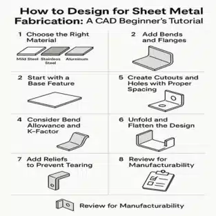
Step-by-Step Beginner’s Guide to Sheet Metal Design

1. Choose the Right Material

Before you start designing, understand the properties of your sheet metal material. Common materials include:

  • Mild steel – affordable and easy to form
  • Stainless steel – corrosion-resistant but harder to bend
  • Aluminium – lightweight and corrosion-resistant
  • Copper and brass – used in decorative and electrical applications

Each material has different thicknesses, minimum bend radii, and strength characteristics, all of which affect your design.


2. Start with a Base Feature

In CAD, a base flange/tab is typically the starting point. This flat profile acts as the foundation for your design.

  • Begin with a 2D sketch on the top plane.
  • Extrude it to the desired thickness of your sheet.
  • Use the Sheet Metal toolset to convert it into a sheet metal part (if not already using a dedicated sheet metal template).

3. Add Bends and Flanges

Using the CAD software’s bend or flange tools, add the necessary folds and edges to your design.

Key bend considerations:

  • Maintain a minimum bend radius (typically equal to the sheet thickness).
  • Avoid bending too close to holes or edges, as this may lead to cracking or deformation.
  • Use uniform bend directions wherever possible to simplify the manufacturing process.

4. Consider Bend Allowance and K-Factor

When metal bends, it stretches and compresses. This needs to be accounted for in your flat pattern layout using bend allowance and K-factor.

  • Bend Allowance: The arc length of the bend, which must be added to the flat length.
  • K-Factor: A ratio that defines how material stretches during bending (commonly between 0.3 to 0.5 for most materials).

Modern CAD software can calculate this automatically when you input the material and bend radius.


5. Create Cutouts and Holes with Proper Spacing

Holes, slots, and cutouts are common in sheet metal parts, but their placement is crucial.

  • Keep holes at least 2x the material thickness away from bends.
  • Ensure minimum hole diameter is not smaller than the thickness of the material to avoid deformation.
  • Use standard hole sizes wherever possible for tooling efficiency.

6. Unfold and Flatten the Design

Once your model is complete, use your CAD software to generate the flat pattern.

This allows you to:

  • Export DXF files for laser cutting or CNC punching.
  • Validate the manufacturability of your part.
  • Check for interference or overlap in bends or flanges.

7. Add Reliefs to Prevent Tearing

When bending corners or edges, bend reliefs help avoid tearing or warping.

  • Use rectangular or obround reliefs where necessary.
  • Most CAD tools offer preset relief options you can apply automatically.

8. Review for Manufacturability

Before finalising your design:

  • Review for minimum bend radii.
  • Ensure standard tooling can produce the part.
  • Minimise the number of bends and tooling operations where possible.

Sending your design to a fabricator for feedback can help optimise it further.


Best CAD Tools for Sheet Metal Design

  • SolidWorks Sheet Metal Module – Highly intuitive and widely used in industry.
  • AutoCAD Mechanical – Great for 2D layouts and DXF file exports.
  • Fusion 360 – Good for beginners and hobbyists, with built-in flat pattern support.
  • Onshape – Cloud-based and great for collaboration.

Conclusion

Mastering sheet metal design is a valuable skill for any aspiring CAD designer. By understanding the basics—material selection, bending rules, allowances, and proper CAD workflow—you can create parts that are not only functional but also easy and cost-effective to manufacture.

As you grow more confident with your CAD software, you’ll be able to create more complex designs, improve production efficiency, and reduce waste in your fabrication projects.

What is the minimum bend radius in sheet metal design?

The minimum bend radius typically equals the material thickness but may vary based on material type and your specific fabrication process. We recommend checking with your local Australian sheet metal fabricator or supplier, as minimum bend radii can differ between workshops depending on their equipment capabilities. Always consult the material manufacturer’s guidelines and your fabricator’s specifications before finalising your CAD design to avoid costly revisions.

Why is bend allowance important in sheet metal design?

Bend allowance is crucial because it accounts for the material stretch that occurs during the bending process, ensuring your flat patterns are accurate for fabrication. At ASTCAD, we’ve found that overlooking this causes costly errors when your sheet metal parts don’t fit together properly. Different materials and thicknesses require different allowances, which is why we recommend consulting Australian Standards or your fabricator’s specifications. Getting this right means your designs manufacture first time, saving time and money on your project.

How do I prevent tearing near bends?

To prevent tearing near bends, we recommend using bend reliefs, which are small notches cut into the material at the inside corner of bends. You should avoid placing holes or slots too close to bend lines, as this weakens the material in that area. Our experienced drafters typically maintain a minimum distance of at least two times the material thickness from any bend, and we always specify appropriate relief sizes in our CAD drawings to ensure your fabricator can produce quality parts without material failure.

Can I use regular 3D CAD tools for sheet metal design?

Yes, you can use regular 3D CAD tools for sheet metal design, but we recommend using software with dedicated sheet metal modules to streamline your workflow. These specialised tools automatically handle flattening calculations and bend allowances, which saves time and reduces errors when fabricating parts. For Australian manufacturers working to local standards like AS/NZS specifications, dedicated sheet metal features ensure your designs meet compliance requirements. We find that using proper sheet metal functionality helps prevent costly mistakes during production and speeds up communication with your fabrication partners.

What file format should I export for fabrication?

Most fabricators prefer DXF files for flat patterns and 2D cutting.


JH

James Hartley

Senior Mechanical Engineer · BEng (Mechanical), UQ · Member, Engineers Australia · ASTCAD, Brisbane

James has 14 years of hands-on experience delivering CAD design, structural drafting, and engineering documentation across Australia’s mining, oil & gas, and manufacturing sectors. He specialises in SolidWorks, Autodesk Inventor, and AutoCAD for complex multi-discipline projects.

More articles by James Hartley →
HVAC Service

Choosing the right HVAC service provider is essential for maintaining a comfortable and energy-efficient home or workplace. With so many companies in the market, finding a reliable and professional provider can be overwhelming. This step-by-step guide will walk you through everything you need to know to make an informed decision when selecting an HVAC service provider.

Step 1: Understand Your HVAC Needs

Before you start searching for an HVAC service provider, you need to understand what type of service you require. Are you looking for:

  • Routine maintenance?
  • Emergency repair?
  • Installation of a new HVAC system?
  • Energy efficiency consultation?

Understanding your specific needs will help you narrow down your choices and ensure the provider you select specialises in the service you require.

Step 2: Research Local HVAC Service Providers

Start your search by looking for HVAC service providers in your area. Use online platforms like Google, Yelp, or Angi (formerly Angie’s List) to find customer reviews and ratings. Ask friends, family, or neighbours for recommendations. Look for companies that:

  • Have consistently high ratings
  • Are well-established in your area
  • Offer the services you need

Check whether the company has a professional website with detailed information about their offerings.

Step 3: Verify Licensing and Certification

An essential step in choosing the right HVAC service provider is verifying their credentials. Make sure the provider has:

  • Valid state licenses
  • Insurance (liability and worker’s compensation)
  • Certifications like NATE (North American Technician Excellence)

These credentials ensure the technicians are qualified and that you are protected in case of accidents or poor workmanship.

Step 4: Check Experience and Expertise

Experience matters when it comes to HVAC systems. Look for companies that have been in business for several years and have experience with your type of system. Ask if they:

  • Have experience with residential, commercial, or industrial systems
  • Handle your brand or model of HVAC equipment
  • Keep their technicians trained on the latest technology and standards

Experienced professionals are more likely to identify issues quickly and provide long-term solutions.

Step 5: Compare Quotes and Services

Request quotes from at least 3 HVAC service providers. Make sure each quote includes:

  • Labour and material costs
  • Warranties on parts and labour
  • Timeframe for completion
  • Details of services offered

Be cautious of quotes that are significantly lower than others. It may indicate a lack of experience, hidden fees, or subpar materials.

Step 6: Evaluate Customer Service

Good customer service is a sign of a reputable HVAC provider. Pay attention to how they treat you during initial communications. Are they:

  • Responsive to calls or emails?
  • Willing to answer your questions?
  • Transparent about pricing and services?

A company that values its customers will be upfront, helpful, and polite.

Step 7: Check Warranties and Maintenance Plans

Quality HVAC services should come with warranties on parts and labour. Ask about:

  • Manufacturer warranties on equipment
  • Service guarantees
  • Maintenance plans or service agreements

A maintenance plan can save you money in the long run by providing regular system checkups and priority service during emergencies.

Step 8: Review Contracts Before Signing

Before agreeing to any HVAC service, read the contract carefully. Look for:

  • Scope of work
  • Payment terms
  • Warranties and guarantees
  • Cancellation policy

Make sure everything discussed is documented. Never rely on verbal agreements alone.

What should I look for in a good HVAC service provider?

Look for licensed, insured, and certified providers with a solid reputation, good reviews, and experience in the services you need.

Is it necessary to get multiple quotes?

Yes, absolutely. We recommend obtaining at least three quotes from different HVAC service providers to compare pricing, service scope, and warranty offerings. This helps you understand the market rate in your area and identify any hidden fees or unusual charges. When reviewing quotes, ensure they include detailed specifications that meet Australian building codes and standards relevant to your project. Our experience in drafting HVAC systems shows that transparent pricing and comprehensive documentation from the outset prevent costly misunderstandings later.

Should I choose the cheapest HVAC service provider?

Not always. While competitive pricing is important, the cheapest option may indicate inexperienced technicians or substandard workmanship. We recommend evaluating providers based on qualifications, experience with Australian building codes, and warranty offerings alongside cost. Look for engineers and drafters certified by professional bodies like Engineers Australia to ensure compliance with local standards and regulations. True value comes from reliable service, quality designs, and long-term reliability rather than upfront savings.

How often should I schedule HVAC maintenance?

We recommend scheduling HVAC maintenance twice yearly—ideally before summer for cooling systems and before winter for heating systems. For Australian climates, this ensures your systems handle extreme temperature variations effectively. Regular maintenance helps identify potential issues early, improving efficiency and extending equipment lifespan. Our drafting team can also help document your HVAC specifications and maintenance schedules for compliance and future reference.

What is a service agreement, and is it worth it?

A service agreement includes routine maintenance and priority service for emergencies. It’s worth it for long-term savings and peace of mind.


JH

James Hartley

Senior Mechanical Engineer · BEng (Mechanical), UQ · Member, Engineers Australia · ASTCAD, Brisbane

James has 14 years of hands-on experience delivering CAD design, structural drafting, and engineering documentation across Australia’s mining, oil & gas, and manufacturing sectors. He specialises in SolidWorks, Autodesk Inventor, and AutoCAD for complex multi-discipline projects.

More articles by James Hartley →
Mechanical Product

Bringing a mechanical design to life is one of the most powerful ways to communicate how it works. That’s where 3D mechanical product animation comes in. Whether you’re showcasing a gear system, piston movement, or product assembly, animation gives your static CAD models dynamic expression.

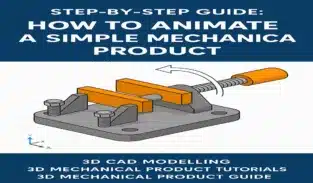
In this blog, we provide a step-by-step guide for beginners on how to animate a simple mechanical product using 3D CAD Modelling tools. Perfect for engineers, product designers, and students, this 3D Mechanical Product Guide covers the essentials of turning your model into a compelling visual story.

Why Animate Mechanical Products?

Before jumping into the steps, let’s understand the benefits of 3D mechanical product animation:

  • Demonstrates product function without physical prototypes
  • Improves communication between design teams and clients
  • Enhances presentations, sales pitches, and instructional materials
  • Reduces errors by visualising motion, fit, and assembly early

Animations are especially useful in industries like manufacturing, automotive, consumer electronics, and machinery.

Tools You’ll Need

To follow this 3D Mechanical Product Tutorial, you’ll need:

  • A 3D CAD software (e.g., Fusion 360, SolidWorks, Autodesk Inventor, Blender)
  • A simple mechanical product model (e.g., clamp, gear system, hinge)
  • Basic knowledge of 3D CAD Modelling

Step-by-Step Guide to Animating a Simple Mechanical Product

Step 1: Create or Import the 3D Model

Start with a clean and complete 3D CAD model of the product. If you’ve already modelled it yourself, ensure all components are separated (as parts) in an assembly environment.

Step 2: Assign Motion Joints or Constraints

In your CAD software, move to the assembly workspace. Define how each component should move:

  • Use revolute joints for rotating parts (like wheels or gears)
  • Use slider joints for parts that move linearly (like pistons)
  • Use rigid joints to lock parts together

These joints replicate real mechanical behaviour and are the foundation of realistic motion.

Step 3: Set Up the Animation Timeline

Open the animation timeline or motion study panel (the name depends on the software). Here, you can add keyframes—snapshots that define object position at a specific time.

  • Set your timeline to a comfortable length (10-20 seconds is good for a demo)
  • Define your first keyframe at time 0
  • Move to a later time (e.g., 5s or 10s) and move the component to a new position

The software will automatically animate the transition between the two positions.

Step 4: Add More Movements

Repeat the keyframe process to animate other parts. For example:

  • Rotate gears
  • Slide a piston
  • Open and close a hinge

Make sure the timing is smooth and mimics real-world mechanical motion.

Step 5: Fine-Tune the Animation

Use the timeline controls to adjust:

  • Speed: Slow down or speed up specific movements
  • Delay: Add a pause between movements for clarity
  • Sequence: Make parts move in the correct logical order

Use preview mode to test how your animation looks and feels.

Step 6: Add Camera Angles (Optional)

To make your animation more engaging, add camera transitions or rotate the view over time. Most CAD tools allow you to animate the camera for walkthroughs or zoom effects.

Step 7: Export the Animation

Once your animation is complete:

  • Export it as a video file (MP4, AVI) or animated GIF
  • Choose the resolution and frame rate
  • Save it for use in presentations, websites, or training material

Common Use Cases for Beginners

  • Showing how parts assemble and disassemble
  • Animating gear rotation or cam motion
  • Simulating a press or clamp mechanism
  • Creating tutorials or promotional demos

These are great starting points to apply your knowledge from this 3D Mechanical Product Guide.

Conclusion

Learning how to animate a mechanical product is a valuable skill that blends design, engineering, and storytelling. This step-by-step 3D Mechanical Product Tutorial has shown that with the right tools and guidance, even beginners can create powerful animations that demonstrate real-world function.

Mastering 3D CAD Modelling is just the beginning—animation takes your mechanical design to the next level. Start with something simple, keep experimenting, and soon you’ll be creating animations that make an impact.

Absolutely. These animations are perfect for explaining how your product works visually without technical jargon.

Do I need to know advanced CAD skills to create animations?

No, you don’t need advanced CAD skills to create animations with ASTCAD. If you have basic knowledge of 3D modelling and assembly work, our step-by-step guides will walk you through the animation process. We’ve designed our tutorials specifically for Australian drafting and engineering professionals who want to showcase mechanical products without needing specialist animation experience. Our team supports you at every stage, making it straightforward to produce professional results.

Which software is best for beginners in 3D mechanical product animation?

We recommend Fusion 360 for Australian beginners, especially if you’re working on smaller mechanical projects or need affordable cloud-based solutions. Its intuitive timeline interface makes learning animation straightforward, while SolidWorks suits those needing advanced motion analysis for complex assemblies. Both integrate well with Australian design standards and local engineering workflows, making either a solid choice depending on your project scope.

Can I animate moving parts even if they are imported from another CAD program?

Yes, as long as the imported files contain separated parts and can be joined with motion constraints.

How long does it take to create a simple mechanical animation?

For a basic product with 2–3 moving parts, our team typically requires 30 minutes to 2 hours depending on complexity and your software familiarity. At ASTCAD, we’ve found that Australian engineering standards and detailed technical specifications can add extra time, but this investment ensures compliance with AS/NZS requirements. The timeline also depends on whether you’re using industry-standard CAD software like AutoCAD or specialist animation tools. We recommend allowing buffer time for revisions to meet your project specifications perfectly.

Can I use these animations in marketing or training videos?

Absolutely. Our animations are perfect for explaining how your product works visually without technical jargon, making them ideal for marketing materials, training videos, and client presentations. At ASTCAD, we design these visualisations to meet Australian engineering standards and can customise them for your specific industry needs, whether you’re in manufacturing, construction, or product development. You’ll have full rights to use your animations across digital platforms and promotional channels.


JH

James Hartley

Senior Mechanical Engineer · BEng (Mechanical), UQ · Member, Engineers Australia · ASTCAD, Brisbane

James has 14 years of hands-on experience delivering CAD design, structural drafting, and engineering documentation across Australia’s mining, oil & gas, and manufacturing sectors. He specialises in SolidWorks, Autodesk Inventor, and AutoCAD for complex multi-discipline projects.

More articles by James Hartley →
Get a free quote — 1800 287 223