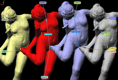
The Future – Desktop 3D Scanning and Manufacturing
Before we finish our series “Everything you always wanted to know about 3D scanning” we wanted to take a moment to talk about what we think is the immediate future in 3D scanning and manufacturing: the technology is going Desktop.
In the last few years, companies have been creating more products with smaller footprints, at much lower price points, making the technology a viable tool for schools and medium to small businesses. In addition to these new products, students and hobbyists have been creating (and sharing) do-it-yourself versions of 3D scanning and rapid manufacturing products. Soon we could see 3D scanners and printers in home offices!
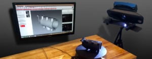
Coming in the near future – to a home workshop near you!
Commercial Desktop and Handheld Scanners:
There are a few digitizers and scanners out there that are sized and priced for the small business. The price points are not yet for your everyday consumer, but it is getting closer all of the time.
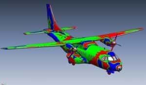
- One of our favourite desktop digitizer/scanners is the Microscribe. It is a miniature articulating arm that is easily portable, is compatible with most popular reverse engineering and metrology packages, and offers near metrology level accuracy in a small package. Obviously you are not going to digitize an aeroplane with this – but we consider it the first major desktop digitizer (an attachable scanner is also available).
- 3D metrology has also entered the realm of handheld and wireless. the microscope also now offer the MobiGage, the first handheld 3D metrology app. You don’t even need a computer, just a Microscribe and an iPhone or iPod Touch, to take measurements.
- Next Engine also offers a desktop 3D laser scanner. Its compact size, ease of use, customer support and price point are quickly making it a popular choice for small businesses and individuals.
Open Source, Consumer and Up-Coming Scanning Technologies:
While they don’t come close to offering the same kind of accuracy as currently available scanning systems, there is a burgeoning community of small businesses, hobbyists and students who are working to bring 3D scanners into the home. New products are rapidly developing.
- Qi Pan, a student at Cambridge University has created ProFORMA, which uses a webcam to collect data and create a colour 3D model.
- David Laser Scanner offers a kit to build your own basic scanning system using everyday objects like a webcam and handheld laser pointer.
- Perhaps the ultimate in DIY scanners, Friederich Kirschner used Legos, a webcam and some milk to create 3D models.
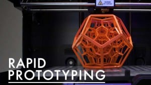
Desktop 3D Printers:
Like 3D scanners, 3D printers have already reached the small business market and are now just entering the individual consumer marketplace. Their build envelopes are limited but what could be cooler than printing your own action figures, robot parts, or 3D portraits?
Desktop 3D Scanning and Manufacturing
- The RepRap project is an open-source project aimed at creating self-replication rapid manufacturing machines. Based out of Bath University, the project shares its plans and the RepRap community can build as is or make their own improvements, which they can then share.
- At the other end of the Desktop 3D printer spectrum comes the V Flash from 3D Systems. Rather than making your 3D printer from scratch, you can buy this smaller version of traditional additive manufacturing technology. It is priced for small businesses and schools.
- In the same market space as the V Flash, Solido bills their SolidPro300 as the “world’s most cost-efficient and flexible 3D printer”. In the US the SolidPro300 is distributed by Enser.
- Between RepRap, the V Flash, and SolidPro300 comes to the Makerbot Cupcake CNC. Makerbot sells a kit for the Cupcake CNC but the customer puts it together. Like RepRap, they also host a community called Thingverse. Though their community revolves more around the 3D models than the machine itself. They are also working on a 3D scanning kit.
- HP has also recently announced that they are entering the market in an agreement with Stratysis who will produce mainstream 3D printers using Fused Deposition Modeling technology.
The above examples are just a small selection from a quickly developing marketplace, but they are a good indication of what home scanning technologies are just around the corner. Thanks for reading “Everything you always wanted to know about 3D scanning”, we hope it is has been an informative series!
Contact Australian Design & Cad Drafting Services for more information..
What is 3D scanning being used for in smart manufacturing?
In smart manufacturing, 3D scanning is being used for various purposes to improve efficiency, accuracy, and quality throughout the production process. Some of the key applications of 3D scanning in smart manufacturing include:
Quality Control: 3D scanning allows manufacturers to perform detailed inspections of components and products to ensure they meet quality standards. By capturing precise 3D measurements and comparing them to CAD models or reference specifications, manufacturers can identify defects, deviations, or inconsistencies early in the production process, minimizing scrap and rework.
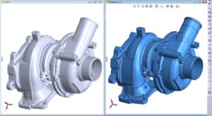
Reverse Engineering: 3D scanning enables manufacturers to quickly and accurately capture the geometry of existing parts or products for reverse engineering purposes. This is particularly useful when replicating legacy components, optimizing designs for aftermarket parts, or creating digital archives of physical objects. By digitizing real-world objects, manufacturers can streamline the design iteration process and accelerate product development cycles.
Tooling and Fixture Design: Manufacturers use 3D scanning to create digital models of tooling, fixtures, and molds used in the manufacturing process. By scanning existing tooling or physical prototypes, designers can quickly generate accurate 3D models that can be refined, optimized, and simulated digitally before fabrication. This helps minimize lead times, reduce costs, and improve the performance of manufacturing equipment.
Customization and Personalization: 3D scanning enables manufacturers to capture precise measurements of individual components or products, allowing for customized or personalized manufacturing solutions. Whether it’s creating bespoke medical implants, tailored consumer products, or customized automotive parts, 3D scanning facilitates the production of highly customized products that meet the unique needs and preferences of customers.
Digital Twins: By combining 3D scanning with other digital technologies such as IoT sensors and data analytics, manufacturers can create digital twins of physical assets, processes, and systems. Digital twins provide real-time insights into the performance, condition, and behavior of manufacturing equipment and facilities, enabling predictive maintenance, process optimization, and continuous improvement initiatives.
Supply Chain Integration: 3D scanning facilitates seamless integration between different stages of the manufacturing supply chain. Manufacturers can use 3D scanning to capture as-built conditions of incoming components or subassemblies, verify dimensional accuracy, and ensure compatibility with downstream processes. This helps improve supply chain visibility, traceability, and quality assurance.
What is 3D scanning in additive manufacturing?
In additive manufacturing (AM), also known as 3D printing, 3D scanning plays a significant role in several aspects of the process:
Digitization of Objects: 3D scanning allows physical objects to be converted into digital models. This is particularly useful for reverse engineering applications, where existing parts or components are scanned to create digital representations. These digital models can then be modified, optimized, or replicated using additive manufacturing techniques.
Design Iteration and Prototyping: 3D scanning enables designers and engineers to capture physical prototypes or mock-ups and incorporate them into the iterative design process. By scanning prototypes and incorporating them into digital design environments, designers can quickly iterate on designs, make modifications, and validate concepts before committing to final production.
Customization and Personalization: With 3D scanning, manufacturers can capture precise measurements of individual customers or objects, allowing for highly customized or personalized products to be produced using additive manufacturing techniques. This is particularly relevant in industries such as healthcare, where custom-fit medical implants and prosthetics can be produced based on patient-specific anatomical data.
Quality Assurance and Inspection: 3D scanning is used for quality assurance and inspection purposes in additive manufacturing. By scanning printed parts and comparing them to the original digital models or specifications, manufacturers can verify dimensional accuracy, surface finish, and overall quality. This helps identify defects, deviations, or inconsistencies early in the production process, reducing scrap and rework.
Process Monitoring and Control: In some additive manufacturing processes, 3D scanning is used for in-situ monitoring and control of the printing process. Real-time scanning and feedback systems can detect defects or anomalies as they occur and make adjustments to printing parameters to ensure the quality and integrity of the printed parts.
Digital Inventory and Archiving: 3D scanning facilitates the creation of digital inventories and archives of additive manufacturing parts and components. By scanning and cataloging printed objects, manufacturers can maintain digital records of their inventory, track usage and consumption, and quickly reproduce parts as needed without the need for physical storage of inventory.