
1800 287 223 · info@astcad.com.au
CAD Automation

In today’s fast-paced engineering and design landscape, efficiency is everything. Computer-Aided Design (CAD) tools have evolved rapidly, and with them comes a powerful game-changer: CAD Automation. Whether you’re an architect, mechanical engineer, or product designer, CAD automation can significantly reduce manual tasks, boost accuracy, and streamline your entire workflow.

In this beginner’s guide, we’ll help you understand what CAD automation is, its benefits, common applications, and how to get started even if you’re new to it.

What is CAD Automation?

CAD Automation refers to the use of scripts, macros, or software tools that automatically generate or modify CAD drawings and models. Instead of manually drawing every line, curve, or component, CAD automation enables repetitive or complex tasks to be performed with minimal human input.

Automation can include anything from automatically updating part numbers in a drawing to generating full assemblies based on predefined parameters. This not only saves time but also enhances precision.

Why Should You Use CAD Automation?

Here are some of the key advantages of integrating CAD automation into your design workflow:

  1. Increased Efficiency
    Automating repetitive tasks frees up valuable time. Engineers and designers can focus more on creativity and problem-solving.
  2. Reduced Human Error
    By removing manual steps, the risk of errors decreases. This results in better quality control and fewer costly revisions.
  3. Improved Consistency
    Automation ensures that the same standards and formatting are applied across all drawings, reducing discrepancies.
  4. Faster Project Turnaround
    With automated workflows, project timelines shrink. What used to take hours can now be done in minutes.
  5. Scalability
    As your project scope grows, automation scales with you. It handles complexity more effectively than manual processes.

Common Applications of CAD Automation

CAD automation is used across multiple industries. Here are some practical applications:

  • Automated Drawing Generation: Generate detailed 2D drawings from 3D models with a single click.
  • Parameter-Driven Design: Create models that update automatically when you change a few key variables (length, width, material).
  • BOM (Bill of Materials) Automation: Automatically update parts lists, descriptions, and quantities.
  • Batch File Processing: Apply changes or renderings across multiple files simultaneously.
  • Custom Plug-ins and Macros: Streamline specific workflows within CAD software like AutoCAD, SolidWorks, or Inventor.

How to Get Started with CAD Automation

Getting started may sound intimidating, but it’s easier than you think. Follow these beginner-friendly steps:

1. Understand Your Current Workflow

Begin by identifying tasks you do repeatedly. These are perfect candidates for automation. Examples include inserting standard components, exporting files, or updating title blocks.

2. Choose the Right CAD Software

Most modern CAD platforms like AutoCAD, SolidWorks, Fusion 360, and Revit offer automation features or support scripting languages like Python, LISP, or VBA.

3. Start Small with Built-in Tools

Explore built-in automation options first:

  • In AutoCAD, use Action Recorder to create macros.
  • In SolidWorks, try Design Tables and Macros.
  • In Fusion 360, leverage parametric design capabilities.

4. Learn Basic Scripting

Learning a basic scripting language like AutoLISP (for AutoCAD) or Python (for Fusion 360) will unlock powerful automation potential. Plenty of free resources are available online.

5. Use Plugins and APIs

Consider installing third-party plugins or working with your software’s API (Application Programming Interface) to build custom tools tailored to your workflow.

6. Test and Refine

Start with simple scripts and test them on smaller projects. Gradually build up as your confidence grows. Debug and optimise regularly.

7. Consult with CAD Automation Experts

If your project is large or highly specific, consulting a professional CAD automation service (like ASTCAD) can accelerate your setup and deliver tailored automation solutions.

Best Practices for CAD Automation

  • Keep your scripts organised and documented.
  • Regularly backup your original files before running automation.
  • Use version control for your macros or scripts.
  • Test new automation tools in a sandbox environment.
  • Keep learning and stay updated with the latest CAD trends.

Final Thoughts

CAD Automation is revolutionizing the way engineers and designers work. Whether you’re looking to speed up drafting, reduce errors, or scale your design process, automation offers a smart, efficient solution. By starting small and gradually building your knowledge, even beginners can take full advantage of this powerful technology.

Ready to automate your CAD workflow? Reach out to ASTCAD today and discover how our CAD Automation services can elevate your project efficiency and accuracy.

Is CAD automation only for advanced users?

Not at all. At ASTCAD, we’ve designed our automation tools to suit all skill levels, from beginners using our action recorders to experienced users writing custom scripts. Whether you’re working on residential plans, commercial drawings, or infrastructure projects compliant with Australian standards, you can start automating tasks immediately without any coding knowledge. As your confidence grows, you can explore more advanced features like parametric design and APIs to further streamline your workflow.

What software supports CAD automation?

At ASTCAD, we work with the most popular CAD platforms used by Australian drafters and engineers, including AutoCAD, Revit, and Fusion 360, all of which offer robust automation capabilities through APIs and scripting languages. Whether you’re designing architectural plans, engineering drawings, or construction documentation, we can help you implement automation tailored to Australian standards and workflows to significantly reduce repetitive tasks and boost productivity.

Can CAD automation integrate with other systems?

Yes, CAD automation integrates seamlessly with your existing systems including ERP, PLM, and project management platforms through APIs and custom connectors. We’ve helped Australian engineering firms link their CAD workflows with accounting software, inventory systems, and client databases to eliminate manual data entry and improve accuracy. Our solutions ensure your design data flows automatically between platforms, reducing errors and keeping all teams synchronized in real-time. Whether you’re managing large infrastructure projects or architectural drawings, we can configure integrations tailored to your specific Australian industry requirements and compliance needs.

Is it expensive to implement CAD automation?

At ASTCAD, we’ve found that CAD automation is more affordable than many Australian firms expect. Basic automation using built-in tools costs nothing, while custom solutions for your specific workflows depend on complexity and scale. We recommend starting with free features to see the impact, then investing in advanced automation as your team grows. Many of our clients recoup costs quickly through improved productivity and fewer design revisions, making it a smart investment for competitive Australian engineering practices.

How do I find the right CAD automation service provider?

Look for providers with proven experience in your industry and a strong track record of successful projects. We at ASTCAD specialize in Australian drafting and engineering standards, offering customized CAD automation solutions that streamline your workflow and reduce design time. Check client reviews, request case studies, and ensure the provider understands local compliance requirements and industry-specific needs relevant to your projects.

JH

James Hartley

Senior Mechanical Engineer · BEng (Mechanical), UQ · Member, Engineers Australia · ASTCAD, Brisbane

James has 14 years of hands-on experience delivering CAD design, structural drafting, and engineering documentation across Australia’s mining, oil & gas, and manufacturing sectors. He specialises in SolidWorks, Autodesk Inventor, and AutoCAD for complex multi-discipline projects.

More articles by James Hartley →
Structural Steel Shop Drawings

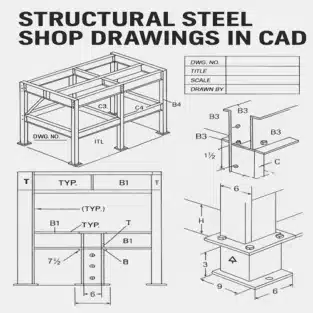
Creating accurate structural steel shop drawings is a critical step in any steel construction project. These drawings ensure that every steel component is fabricated and installed precisely according to the engineering intent. If you’re new to CAD or steel detailing, this guide will walk you through the process step by step.

AutoCAD Steel Structure Drawing: What Are Shop Drawings?

Structural steel shop drawings are detailed and scaled plans used by fabricators to manufacture steel components. Unlike general design drawings, these include precise dimensions, material specifications, welding details, hole locations, and assembly instructions.

They serve as the final blueprint before steel elements are cut, welded, and assembled, and are often required for approval by engineers, architects, and contractors.

Software You Can Use for Structural Steel Shop Drawings

Several CAD programs are commonly used, including:

  • AutoCAD
  • Tekla Structures
  • Advance Steel
  • Revit (with extensions)

Each offers different features. For this tutorial, we’ll focus on AutoCAD, a widely used platform that supports 2D drafting and can be adapted for steel detailing.

Step-by-Step Guide: Creating Structural Steel Shop Drawings in CAD

Step 1: Set Up the Drawing Environment

  • Open AutoCAD and set the drawing units to millimetres or inches (as per your project standards).
  • Create or import a title block that includes project name, drawing number, date, scale, and drafter initials.
  • Set up layers for different elements (e.g., beams, columns, annotations, centerlines).

Step 2: Import or Reference the Structural Model

  • If you have a 3D model from the design team, insert it as an XREF or import it as a DWG.
  • Use this as a base to extract or reference key dimensions and member locations.

Step 3: Identify Structural Steel Elements

  • Break down the project into individual parts: columns, beams, base plates, gusset plates, stiffeners, etc.
  • Refer to the structural design drawings to determine steel profiles (e.g., W-beams, HSS, angles).

Step 4: Draft Individual Components

  • Start with 2D views: top, side, and section views of each component.
  • Draw accurate profiles of steel sections using standard dimensions from the AISC or your regional steel handbook.
  • Add cutting lengths, hole diameters, and weld symbols.

Step 5: Add Annotations and Labels

  • Clearly label each part with:
    • Part number or mark
    • Material specification
    • Quantity required
    • Welding instructions
  • Use leader lines and callouts to avoid clutter.

Step 6: Add Assembly and Erection Drawings

  • Once individual parts are drafted, create assembly drawings showing how parts are connected.
  • Include:
    • Bolt sizes and patterns
    • Weld sizes and types
    • Connection plates and stiffeners
  • Provide erection sequences and reference the orientation of members.

Step 7: Apply Dimensions and Tolerances

  • Use dimension tools to indicate:
    • Overall lengths
    • Hole centers
    • Edge distances
    • Weld lengths
  • Always apply standard tolerances as per AISC or project specifications.

Step 8: Double-Check for Errors

  • Cross-check:
    • Member sizes with the structural drawings
    • Fabrication feasibility
    • Consistency in labelling and material specs
  • Use AutoCAD’s Audit and Layer Manager tools to clean up the drawing.

Step 9: Export and Submit for Review

  • Save your file in DWG and PDF format.
  • Submit to the structural engineer or quality control team for approval.
  • After review, incorporate any markups or revisions before final submission to the fabricator.

Tips for Beginners

  • Use templates: Create reusable templates for beams, columns, and plates.
  • Keep it clean: Use layers and line weights effectively to improve readability.
  • Stay organised: Number every drawing sheet and keep a drawing log.
  • Refer to standards: Always follow AISC, BS, or IS standards based on your project location.

Why Structural Steel Shop Drawings Are Essential

Without detailed and accurate structural steel shop drawings, fabrication errors, delays, and costly onsite modifications become inevitable. These drawings bridge the gap between engineering intent and real-world execution.

Conclusion

Creating your first structural steel shop drawings in CAD may feel overwhelming, but following a systematic approach ensures accuracy and efficiency. With practice and adherence to industry standards, you’ll be able to produce shop drawings that meet the demands of any steel fabrication project.

For professional assistance in generating high-quality shop drawings, reach out to ASTCAD—your trusted partner for structural CAD drafting services.

What’s the difference between structural drawings and shop drawings?

Structural drawings are created by engineers to convey the overall design intent and are typically stamped by a Professional Engineer. Shop drawings are prepared by fabricators and detailers like our team to show precisely how each component will be manufactured, assembled, and erected on site. In Australia, shop drawings must comply with AS/NZS 5131 standards and are critical for construction approval and fabrication accuracy.

Are 3D models required for structural steel shop drawings?

While not mandatory, 3D models help visualize complex connections and are increasingly used to coordinate with BIM workflows. In Australia, many projects now require 3D coordination to comply with design standards and facilitate shop fabrication. We recommend creating at least a basic 3D model to catch clashes early and improve communication with fabricators and contractors on-site.

How accurate should shop drawings be?

Extremely accurate—down to the millimeter. Any discrepancy can cause misfits during assembly.

Who approves structural steel shop drawings?

In Australia, the structural engineer of record typically approves shop drawings, often in consultation with the project architect and relevant certifiers. We recommend submitting your drawings through your engineer’s review process, as they’ll verify compliance with the design documentation, Australian Standards (AS 4100 for steel structures), and any state-based building codes. Most fabricators won’t commence work until formal approval is stamped and signed off. We can help you prepare drawings that streamline this approval process.

Can I create structural steel shop drawings without AutoCAD?

Yes, software like Tekla Structures and Advance Steel are more advanced and tailored for steel detailing, but AutoCAD remains a widely accessible tool for 2D shop drawings.


JH

James Hartley

Senior Mechanical Engineer · BEng (Mechanical), UQ · Member, Engineers Australia · ASTCAD, Brisbane

James has 14 years of hands-on experience delivering CAD design, structural drafting, and engineering documentation across Australia’s mining, oil & gas, and manufacturing sectors. He specialises in SolidWorks, Autodesk Inventor, and AutoCAD for complex multi-discipline projects.

More articles by James Hartley →
Structural Floor Plan

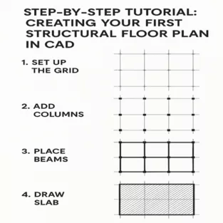
Creating a structural floor plan in CAD might sound like rocket science at first, but trust me—it’s totally doable with the right steps. If you’re diving into structural design and drafting services for the first time, this guide is your go-to resource. Let’s break it down and build your skills, one step at a time!

What is a Structural Floor Plan?

Definition and Purpose

A structural floor plan shows the bones of a building. It focuses on how the building holds itself up—beams, columns, slabs, load-bearing walls, and foundations.

Differences from Architectural Plans

While architectural plans focus on spaces, aesthetics, and user experience, structural plans deal with physics. No pretty tiles or lighting layouts here—just strength and stability.

Understanding the Basics Before You Start

Load-Bearing Elements

You need to know what parts of your design carry the most weight—columns, beams, and structural walls.

Beam and Column Layout

These are the framework of your building—placing them wrong could lead to structural failures.

Slabs and Reinforcements

Slabs are the horizontal components (like floors and ceilings), and they need reinforcement to prevent bending and breaking.

Step 1 – Setting Up Your Workspace

Units and Scales

Start by setting your units (metric or imperial) and scale according to the local standards.

Grid Settings and Templates

Grids help in aligning elements properly. Use templates for consistent results—especially handy when working with large projects.

Step 2 – Import or Draw the Base Layout

Using Architectural Plans as a Reference

Usually, structural floor plans are built over existing architectural plans. Import them to guide your drawing.

Drawing Walls and Structural Elements

Begin sketching the walls that will bear loads. Use line or polyline tools for precise placement.

Step 3 – Placing Columns and Beams

Identifying Column Positions

Columns typically align with corners or intersections of load-bearing walls. Place them symmetrically when possible.

Aligning Beams with Columns

Beams connect the columns and support the slab. Make sure the spacing and alignment are clean and logical.

Step 4 – Designing Slabs

Types of Slabs

  • One-way slabs
  • Two-way slabs
  • Flat slabs

Detailing Slab Reinforcement

Use hatch or line patterns to show rebar layout, including spacing and thickness.

Step 5 – Adding Dimensions and Annotations

Dimensioning Best Practices

Don’t clutter your plan. Use consistent units and spacing. Group related dimensions together.

Labelling Structural Elements

Clearly label each element—beams (B1, B2), columns (C1, C2), and so on. This makes referencing easy during construction.

Step 6 – Checking and Validating Your Plan

Cross-Checking Alignment

Make sure everything lines up—columns, beams, walls. Misalignments can cause on-site issues.

Clash Detection and Load Path Review

Check for elements overlapping improperly and review how loads are transferred through the structure.

Step 7 – Exporting and Printing

File Formats

Export in DWG for CAD, PDF for sharing, and DXF for CNC work.

Plotting and Sharing with Teams

Use proper title blocks and scales before printing. Coordinate with architects and MEP teams.

Tips for Accuracy and Efficiency

Layer Management

Use different layers for beams, columns, slabs, etc., with colour coding. It’ll save you from a ton of confusion later.

Using Blocks and Templates

Reuse components like column blocks or dimension styles. It’s a huge time-saver.

Tips for Accuracy and Efficiency

Layer Management

Use different layers for beams, columns, slabs, etc., with colour coding. It’ll save you from a ton of confusion later.

Using Blocks and Templates

Reuse components like column blocks or dimension styles. It’s a huge time-saver.

Benefits of Using Structural Design and Drafting Services

Time-Saving

These services streamline your workflow by providing ready-to-use floor plans.

Expert Guidance and Precision

They know all the codes, tricks, and traps. When in doubt, it’s smart to outsource.

Common Mistakes to Avoid

Skipping Structural Details

Leaving out reinforcements or slab types is a recipe for disaster. Always be thorough.

Not Coordinating with Other Disciplines

Your structural plan should sync with architectural, plumbing, and electrical plans. Miscommunication here can be costly.

Conclusion

And there you have it—a complete step-by-step tutorial on creating your first structural floor plan in CAD. Whether you’re a beginner or brushing up your skills, these fundamentals will get you started on the right foot. Don’t rush the process, and remember: accuracy today saves time (and money) tomorrow.

What software is best for structural floor planning in CAD?

We recommend AutoCAD for beginners learning structural floor planning basics, though many Australian practices transition to Revit or Tekla for more complex building information modelling. Our team finds Revit particularly valuable for coordinating with engineers and architects on Australian building code compliance, while Tekla excels for detailed steel fabrication drawings. The choice depends on your project complexity and whether you need integrated structural analysis tools aligned with Australian standards.

Do I need architectural plans before making a structural plan?

Yes, architectural plans guide the layout of structural elements like columns and beams.

How long does it take to create a basic structural floor plan?

If you’re new, it might take a few hours. With practice or using Structural Design and Drafting Services, it’s much faster.

Can I design slabs without reinforcement details?

Technically yes, but it’s not recommended. Reinforcement is critical for slab performance and safety.

Why use Structural Design and Drafting Services?

They bring in expert knowledge, ensure compliance with standards, and deliver accurate, ready-to-use plans.


JH

James Hartley

Senior Mechanical Engineer · BEng (Mechanical), UQ · Member, Engineers Australia · ASTCAD, Brisbane

James has 14 years of hands-on experience delivering CAD design, structural drafting, and engineering documentation across Australia’s mining, oil & gas, and manufacturing sectors. He specialises in SolidWorks, Autodesk Inventor, and AutoCAD for complex multi-discipline projects.

More articles by James Hartley →
3D Modelling

If you’re new to 3D modelling and looking for a structured way to sharpen your skills, a 30-day challenge can be the perfect solution. Practising daily not only improves your proficiency but also builds discipline and creativity. Whether you’re a hobbyist, student, or aspiring professional, this 30-day 3D modelling challenge is designed to guide beginners through fun and practical exercises that lay a strong foundation.

Why a 30-Day 3D Modelling Challenge?

The key to mastering any skill is consistency. With 3D modelling, the more time you spend experimenting with tools, shapes, and designs, the more confident you become. This challenge gives you a clear path to follow so you can avoid feeling overwhelmed or stuck. By the end of 30 days, you’ll have a mini portfolio of your progress and a deeper understanding of modelling techniques.

Tools You’ll Need

Before you start, pick a 3D modelling software that suits your level and goals. Popular beginner-friendly programs include:

  • Blender (Free, powerful, great community support)
  • TinkerCAD (Web-based, simple UI, ideal for absolute beginners)
  • Fusion 360 (Great for product design and engineering)
  • SketchUp (Ideal for architectural and interior modelling)

Choose one and stick with it for the full challenge to build muscle memory.

30-Day 3D Modelling Challenge Breakdown

Here’s your step-by-step guide. Each task increases slightly in complexity and introduces new skills:

Week 1: Fundamentals and Basic Shapes

  • Day 1: Explore the interface of your software
  • Day 2: Create basic 3D shapes (cube, sphere, cylinder)
  • Day 3: Practice scaling, rotating, and moving objects
  • Day 4: Combine shapes to make a simple object (e.g., a cup)
  • Day 5: Learn about mesh editing or modifiers
  • Day 6: Create a chair using primitives
  • Day 7: Reflect and organise your files

Week 2: Intermediate Objects and Techniques

  • Day 8: Model a table or desk
  • Day 9: Learn how to use extrusion tools
  • Day 10: Model a lamp or bottle
  • Day 11: Practice beveling and smoothing
  • Day 12: Add simple textures or colours
  • Day 13: Model a simple house
  • Day 14: Render your favourite model so far

Week 3: Complex Objects and Environment Design

  • Day 15: Model a book or stack of books
  • Day 16: Create a basic room layout
  • Day 17: Add furniture to your room
  • Day 18: Learn to use arrays or mirror modifiers
  • Day 19: Model a plant or decorative item
  • Day 20: Use lighting for better visualisation
  • Day 21: Showcase your full room in a rendered scene

Week 4: Creativity and Portfolio Building

  • Day 22: Choose your favourite object and recreate it with improvements
  • Day 23: Start modelling a custom character or mascot
  • Day 24: Add more detail and texture to your model
  • Day 25: Model a vehicle or mechanical object
  • Day 26: Animate a simple scene (e.g., rotating fan)
  • Day 27: Fix errors or redo models from earlier days
  • Day 28: Prepare your best works for a portfolio
  • Day 29: Create a collage or presentation of your models
  • Day 30: Share your work online or with friends

Tips to Stay Motivated

  • Set a timer for 30–60 minutes each day
  • Join online communities like Reddit’s r/3Dmodeling or Blender Artists
  • Don’t aim for perfection—focus on progress
  • Keep a digital folder of each day’s work

Conclusion

The journey to becoming proficient in 3D modelling doesn’t have to be daunting. With a structured 30-day challenge, you can make tangible progress and develop a strong foundation. Whether your goal is to create game assets, product designs, or architectural models, daily practice will set you up for success.

Keep modelling, stay curious, and don’t be afraid to experiment—your next design might be your best yet!

How long should I practice 3D modeling daily as a beginner?

Aim for at least 30–60 minutes each day. Consistent short sessions are more effective than occasional long ones.

What is the best software for learning 3D modeling?

Blender is one of the most popular free programs. It’s powerful and supported by a vast online community. TinkerCAD is better for absolute beginners, especially younger users.

Do I need a powerful computer for 3D modeling?

Not necessarily. Basic 3D modeling tasks can be performed on most mid-range computers. However, for rendering or animation, a better graphics card helps.

Can I learn 3D modeling without any prior design experience?

Absolutely! Our 30-day challenge is specifically designed for complete beginners with no prior design experience. Many CAD tools, including those we recommend at ASTCAD, offer beginner-friendly interfaces that let you start with simple sketches and gradually progress to complex 3D models. We’ve guided thousands of Australian drafting and engineering students through this exact journey, so you’re in good hands starting your CAD learning today.

How can I tell if I’m improving in 3D modeling?

The best way to track your progress is to compare your early models with your recent work, looking for improvements in design smoothness, proportions, and detail complexity. You’ll also notice faster tool proficiency and greater confidence when tackling complex geometry. At ASTCAD, we recommend keeping a portfolio folder of your weekly projects so you can visually document your development. Many of our Australian engineering clients find that reviewing compliance with AS/NZS standards in your models is another great indicator of growing expertise and professional readiness.


JH

James Hartley

Senior Mechanical Engineer · BEng (Mechanical), UQ · Member, Engineers Australia · ASTCAD, Brisbane

James has 14 years of hands-on experience delivering CAD design, structural drafting, and engineering documentation across Australia’s mining, oil & gas, and manufacturing sectors. He specialises in SolidWorks, Autodesk Inventor, and AutoCAD for complex multi-discipline projects.

More articles by James Hartley →
2D CAD Drawings

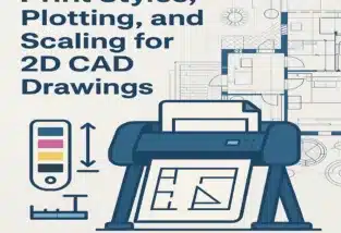
Setting up to print CAD drawings correctly starts with plot styles. Creating precise and professional-quality 2D CAD drawings requires proper setup of print styles, plotting configurations, and scaling adjustments. Whether you’re an architect, engineer, or designer, understanding these aspects ensures that your final printed drawings maintain clarity and accuracy. In this guide, we will cover the essential steps for setting up print styles, configuring plotting settings, and applying appropriate scaling for your 2D CAD drawings.

Understanding Print Styles in 2D CAD Drawings

Print styles define how different elements in a CAD drawing appear when printed. These styles control properties such as line weight, colour, and transparency, ensuring consistency and readability.

Types of Print Styles

  1. Named Print Styles (STB – Style Table Files)
    • Allows customisation of object properties.
    • Different objects can have unique styles.
    • Useful for complex projects requiring specific appearance settings.
  2. Color-Dependent Print Styles (CTB – Color Table Files)
    • Assigns properties based on object colours.
    • Each colour is mapped to a specific line weight or plot setting.
    • Suitable for simpler workflows where colour coding is standard.

How to Set Up Print Styles in AutoCAD

  1. Open Page Setup Manager (Type PAGESETUP in the command line).
  2. Select an existing layout or create a new one.
  3. Click on Plot Style Table (STB or CTB) and choose a predefined style or create a custom one.
  4. Adjust the line weight, screening, and transparency settings.
  5. Save and apply the print style to your drawing.

Configuring Plotting for 2D CAD Drawings

Plotting refers to the process of sending the 2D CAD drawing to a printer or creating a digital output like a PDF.

Steps to Configure Plotting in AutoCAD

  1. Open the Plot Dialogue Box
    • Type PLOT in the command line or press Ctrl + P.
  2. Select a Printer or Plotter
    • Choose a physical printer or DWG to PDF for digital outputs.
  3. Set Paper Size and Orientation
    • Pick the correct paper size (A3, A4, etc.).
    • Choose portrait or landscape mode.
  4. Specify Plot Area
    • Options:
      • Display (Plots everything visible on screen).
      • Extents (Plots everything in the drawing).
      • Window (Select a specific area).
  5. Adjust Plot Scale
    • Match the scale with the drawing units (e.g., 1:100, 1:50, etc.).
    • Ensure “Fit to Paper” is unchecked for precise scaling.
  6. Choose Plot Style Table (CTB/STB)
    • Select an appropriate print style to control line weights and colours.
  7. Preview and Print
    • Click Preview to check before final plotting.
    • Hit OK to generate the output.

Scaling in 2D CAD Drawings

Scaling ensures that drawings are printed at the correct size and proportion. Incorrect scaling can lead to misinterpretation of dimensions and layout errors.

Types of Scaling in 2D CAD Drawings

  1. Model Space Scaling
    • The drawing is created at a 1:1 scale.
    • Dimensions and text should be adjusted using annotation scaling.
  2. Paper Space Scaling (Layouts)
    • Viewports allow setting different scales for different views.
    • Common scales: 1:1, 1:50, 1:100, etc.

How to Set Up Scaling in AutoCAD

  1. Switch to Layout Tab
  2. Create a New Viewport (Type MVIEW and specify the area).
  3. Select the Viewport and Adjust Scale
    • Click on the viewport boundary.
    • Set the desired scale in the properties panel (e.g., 1:100).
  4. Lock the Viewport Scale
    • Prevents accidental zooming or changes.
  5. Check and Finalise
    • Ensure all annotations, dimensions, and title blocks align with the scale.

Conclusion

Setting up print styles, configuring plotting settings, and applying proper scaling are essential for producing professional 2D CAD drawings. By following the steps outlined above, you can ensure that your drawings are clear, accurate, and well-formatted for printing or digital sharing. Properly configured 2D CAD drawings not only improve workflow efficiency but also enhance communication with clients and stakeholders.

Would you like assistance with custom templates or troubleshooting specific plotting issues? Let us know!


JH

James Hartley

Senior Mechanical Engineer · BEng (Mechanical), UQ · Member, Engineers Australia · ASTCAD, Brisbane

James has 14 years of hands-on experience delivering CAD design, structural drafting, and engineering documentation across Australia’s mining, oil & gas, and manufacturing sectors. He specialises in SolidWorks, Autodesk Inventor, and AutoCAD for complex multi-discipline projects.

More articles by James Hartley →
2D CAD Drafting

In the modern world of engineering, architecture, and design, 2D CAD Drafting plays a crucial role in creating accurate and detailed technical drawings. Whether you’re a student, a beginner, or a professional transitioning to CAD, understanding the basics is essential. This guide will help you get started with 2D CAD Drafting, covering essential tools, best practices, and common FAQs to make your journey smoother.

What is 2D CAD Drafting?

2D CAD Drafting refers to the creation of two-dimensional technical drawings using 2D CAD drafting (CAD) software. These drawings include floor plans, schematics, mechanical parts, and electrical layouts. Unlike hand-drawn sketches, 2D CAD Drafting provides precision, scalability, and ease of modification.

Essential Tools for 2D CAD Drafting

To get started with 2D CAD Drafting, you need the following tools:

1. CAD Software

Popular 2D CAD Drafting software includes:

  • AutoCAD – The industry standard for engineering and architectural drafting.
  • DraftSight – A cost-effective alternative for professionals and students.
  • BricsCAD – A user-friendly software compatible with DWG files.
  • LibreCAD – A free and open-source tool for basic drafting needs.

2. Hardware Requirements

A good computer setup enhances efficiency in 2D CAD Drafting. Recommended specifications include:

  • A multi-core processor (Intel i5/i7 or AMD Ryzen 5/7)
  • At least 8GB RAM (16GB preferred for complex projects)
  • A dedicated graphics card (NVIDIA or AMD recommended)
  • A high-resolution monitor for detailed viewing

3. Input Devices

  • Mouse with a scroll wheel – Essential for zooming and panning.
  • Graphic tablet (optional) – Useful for freehand sketching and annotations.

Step-by-Step Guide to Getting Started

Step 1: Install and Set Up the Software

Download and install your preferred 2D CAD Drafting software. Ensure your system meets the required specifications. Customise toolbars, templates, and shortcuts to streamline your workflow.

Step 2: Learn Basic Commands

Familiarize yourself with essential 2D CAD Drafting commands:

  • LINE (L) – Draws straight lines.
  • CIRCLE (C) – Creates circles.
  • RECTANGLE (REC) – Draws rectangles.
  • OFFSET (O) – Copies objects at a specified distance.
  • TRIM (TR) – Removes excess parts of objects.
  • EXTEND (EX) – Lengthens objects to meet other lines.

Step 3: Create Your First Drawing

  • Open a new drawing file.
  • Set up the drawing units (metric or imperial).
  • Use layers to organise elements (e.g., walls, dimensions, annotations).
  • Start with simple shapes and gradually progress to complex designs.

Step 4: Add Dimensions and Annotations

Accurate dimensions are crucial in 2D CAD Drafting. Use:

  • Linear dimensions for straight measurements.
  • Radial and diametric dimensions for circles and arcs.
  • Text annotations to add notes and descriptions.

Step 5: Save and Export Your Work

Save your work in different formats:

  • DWG/DXF – Standard file formats for CAD drawings.
  • PDF – For sharing and printing.
  • PNG/JPEG – For presentations.

Best Practices for Beginners

  • Use Layers: Organise different components for easy editing.
  • Set Object Snaps (OSNAP): Helps in precise placement.
  • Use Keyboard Shortcuts: Increases speed and efficiency.
  • Save Regularly: Prevents data loss in case of system failure.
  • Keep Learning: Explore tutorials, forums, and online courses.

2D CAD Drafting is an essential skill for professionals in various industries. By learning the basics, practising essential commands, and following best practices, beginners can quickly become proficient. Whether you are designing floor plans, mechanical parts, or schematics, mastering 2D CAD Drafting will improve your accuracy and efficiency in technical drawing creation. Keep exploring and refining your skills to stay ahead in the field!

Are you ready to start your journey with 2D CAD Drafting? Let us know your thoughts and experiences in the comments!

What is the best software for beginners in 2D CAD Drafting?

For Australian beginners in 2D CAD drafting, we recommend AutoCAD for comprehensive features and professional-standard outputs, or LibreCAD if you’re looking for a free, user-friendly alternative. Both software options work well with Australian standards and building codes. We find that AutoCAD’s extensive tools help you transition into more complex projects, while LibreCAD offers excellent value for learning fundamental drafting skills without financial commitment.

Can I learn 2D CAD Drafting without prior design experience?

Yes! Many online courses and tutorials make learning 2D CAD Drafting accessible even for beginners with no prior experience.

How long does it take to master 2D CAD Drafting?

Basic proficiency in 2D CAD drafting typically takes a few weeks of consistent practice, especially if you’re following Australian building standards and conventions. However, mastering advanced techniques and becoming highly skilled can take several months to a year, depending on your dedication and the complexity of projects you work on. We recommend starting with fundamental tools and gradually progressing to more sophisticated features used in Australian construction and engineering workflows.

What industries use 2D CAD Drafting?

Industries such as architecture, mechanical engineering, electrical design, and civil engineering rely on 2D CAD Drafting for technical drawings.

Can I convert hand-drawn sketches to 2D CAD Drafting?

Yes, absolutely! At ASTCAD, we can convert your hand-drawn sketches into professional 2D CAD drawings that comply with Australian Standards. Simply scan your sketch and send it to our team, and we’ll digitise it using industry-standard software, ensuring accuracy and compliance with AS 1100 drafting conventions. This approach is ideal for clients who prefer working from conceptual drawings before formal documentation begins.


JH

James Hartley

Senior Mechanical Engineer · BEng (Mechanical), UQ · Member, Engineers Australia · ASTCAD, Brisbane

James has 14 years of hands-on experience delivering CAD design, structural drafting, and engineering documentation across Australia’s mining, oil & gas, and manufacturing sectors. He specialises in SolidWorks, Autodesk Inventor, and AutoCAD for complex multi-discipline projects.

More articles by James Hartley →
CAD Drafting Services

In today’s fast-paced industrial world, CAD Drafting Services play a crucial role in streamlining mechanical design and drafting projects. With the evolution of technology, traditional drafting methods have been replaced by Mechanical CAD Drafting (CAD), offering precision, efficiency, and flexibility. Whether you are designing complex machinery or small mechanical components, leveraging CAD Drafting Services can significantly enhance your project’s outcome.

1. What is CAD Drafting?

CAD (Mechanical CAD Drafting) drafting involves the use of specialised software to create precise mechanical drawings and designs. It eliminates human errors associated with manual drafting and improves the overall accuracy and efficiency of Mechanical Design and Drafting Projects.

2. Advantages of CAD Drafting Services

1. Improved Accuracy and Precision

One of the primary benefits of using CAD Drafting Services is the unmatched accuracy it offers. Unlike hand-drawn sketches, CAD software allows engineers to create detailed and exact mechanical designs with minimal errors.

2. Enhanced Productivity and Efficiency

By automating repetitive tasks, CAD software saves time and effort. Engineers can quickly make modifications, update designs, and optimise drawings without starting from scratch. This results in a significant boost in productivity for Mechanical Design and Drafting Projects.

3. Better Visualisation and 3D Modelling

CAD drafting enables engineers to visualise designs in both 2D and 3D. This helps in understanding how different mechanical components fit together, identifying potential issues before production, and making necessary adjustments.

4. Cost Savings

Using CAD Drafting Services reduces material wastage and minimises costly design errors. Additionally, improved efficiency leads to lower labour costs, making CAD an economically viable solution for mechanical projects.

5. Faster Design Modifications

Mechanical projects often require modifications and adjustments. With CAD, changes can be implemented quickly without disrupting the entire design, allowing for a smoother workflow.

6. Standardisation and Compliance

CAD software ensures that all designs adhere to industry standards and regulations. This is essential in mechanical engineering, where compliance with safety and quality norms is crucial.

7. Easy Collaboration and File Sharing

In mechanical projects, collaboration among multiple teams is essential. CAD software allows seamless file sharing, making it easier for teams to work together, review designs, and implement necessary changes efficiently.

3. Applications of CAD Drafting in Mechanical Projects

1. Machine Component Design

CAD drafting is used extensively in designing mechanical parts, ensuring precise measurements and specifications for efficient manufacturing.

2. Product Development and Prototyping

With CAD, engineers can develop prototypes digitally before moving to production, reducing time and costs in product development.

3. Manufacturing Process Optimisation

By using CAD drafting, manufacturers can optimise production workflows, improve efficiency, and reduce errors during fabrication and assembly.

4. HVAC and Piping Systems

CAD drafting is widely used in designing heating, ventilation, and air conditioning (HVAC) systems, as well as complex piping layouts in industrial setups.

4. Choosing the Right CAD Drafting Service Provider

1. Experience and Expertise

Look for a service provider with extensive experience in Mechanical Design and Drafting Projects to ensure high-quality results.

2. Software Proficiency

Ensure the provider uses industry-standard CAD software like AutoCAD, SolidWorks, or CATIA for reliable and efficient drafting.

3. Customisation and Flexibility

A good CAD drafting service should offer customisation options to meet the specific needs of your mechanical project.

4. Cost-Effectiveness

Compare pricing and service offerings to choose a provider that offers the best value for your investment.

Conclusion

The adoption of CAD Drafting Services in Mechanical Design and Drafting Projects is a game-changer in the engineering industry. With benefits such as improved accuracy, cost savings, enhanced productivity, and better collaboration, CAD drafting is indispensable for mechanical projects. Whether you’re designing small machine parts or large industrial systems, CAD ensures efficiency, precision, and compliance with industry standards.

What industries benefit from CAD drafting services?

Industries such as automotive, aerospace, manufacturing, HVAC, and construction benefit significantly from our CAD drafting services. In Australia, we support mining and resources sectors, infrastructure projects, and renewable energy developments where precision drafting is critical. Our expertise helps businesses meet Australian Standards, reduce design errors, and accelerate project timelines across all these sectors.

What software is commonly used for CAD drafting in mechanical projects?

Popular CAD software for mechanical projects includes AutoCAD, SolidWorks, CATIA, PTC Creo, and Inventor. At ASTCAD, we specialise in these industry-standard tools to deliver precision drafting that meets Australian engineering standards and compliance requirements. Our team stays current with the latest software versions to ensure your mechanical designs are optimised for Australian manufacturing and construction specifications.

How does CAD improve mechanical design efficiency?

CAD dramatically improves mechanical design efficiency by automating repetitive drafting tasks and enabling our engineers to generate accurate technical drawings in a fraction of the time traditional methods require. Our CAD systems allow for quick modifications and real-time collaboration, reducing costly errors before manufacturing begins. Enhanced 3D visualization helps Australian manufacturers understand complex components clearly, streamlining the entire design-to-production process and ultimately saving time and money on your projects.

Can CAD drafting be outsourced?

Yes, many companies outsource CAD Drafting Services to specialized firms to save time, reduce costs, and access expert design capabilities.

How does CAD help in prototyping?

CAD enables digital prototyping, allowing our engineers to test and refine designs before actual manufacturing, reducing costs and development time. We use advanced simulation tools to identify potential issues early, which is particularly valuable for Australian manufacturers working within tight project timelines. Our CAD prototyping services help you avoid costly physical iterations and accelerate your path to production, ensuring your mechanical projects meet both quality standards and budget requirements.


JH

James Hartley

Senior Mechanical Engineer · BEng (Mechanical), UQ · Member, Engineers Australia · ASTCAD, Brisbane

James has 14 years of hands-on experience delivering CAD design, structural drafting, and engineering documentation across Australia’s mining, oil & gas, and manufacturing sectors. He specialises in SolidWorks, Autodesk Inventor, and AutoCAD for complex multi-discipline projects.

More articles by James Hartley →
CAD Drafting

In today’s fast-paced world, modern infrastructure development relies heavily on infrastructure CAD and advanced technologies. From designing skyscrapers to building roads, technology plays a crucial role in ensuring accuracy, efficiency, and sustainability. One of the most essential technologies in this domain is CAD Drafting. It has revolutionized how engineers, architects, and designers create detailed plans and execute large-scale projects.

What is Infrastructure CAD Drafting?

CAD (Computer-Aided Design) Drafting is the process of creating precise technical drawings and blueprints using specialised software. Traditionally, drafting was done manually on paper, but with the advent of CAD technology, it has become digital, making designs more accurate and easier to modify.

Importance of CAD Drafting in Infrastructure Development

Enhancing Accuracy and Precision

Infrastructure projects require extreme precision to ensure safety and functionality. CAD Drafting eliminates human errors and allows for precise measurements, which is critical in construction and engineering.

Improving Efficiency and Productivity

Using CAD Drafting Services, engineers and designers can work faster, create complex designs easily, and make quick modifications, significantly improving project timelines.

Cost-Effectiveness in Large-Scale Projects

Manual drafting is time-consuming and prone to errors, leading to costly rework. CAD Drafting helps in minimising such risks by ensuring accuracy from the beginning, ultimately saving money.

Key Applications of CAD Drafting in Infrastructure

Civil Engineering Projects

CAD Drafting plays a vital role in road construction, bridge design, and urban planning. Engineers use CAD software to create precise blueprints, ensuring structural integrity and efficient land use.

Architectural Design

Modern residential and commercial buildings rely on CAD Drafting for designing interiors, exteriors, and structural layouts. Additionally, smart city planning involves detailed CAD models for optimising space and resources.

Structural Engineering

From reinforced concrete structures to earthquake-resistant buildings, CAD helps engineers visualise the impact of different forces on structures before actual construction.

Mechanical and Electrical Systems

CAD Drafting is essential for designing HVAC systems, piping layouts, and electrical circuit diagrams. It ensures efficient space utilisation and seamless integration with infrastructure.

How CAD Drafting Services Benefit Infrastructure Projects

Accuracy and Consistency

CAD Drafting ensures high accuracy by reducing human errors and providing a standardised approach for designing multiple projects.

Faster Revisions and Modifications

Designs often undergo changes, and CAD allows easy modifications without redrawing entire blueprints, saving time and effort.

3D Visualisation and Simulation

With 3D CAD Modelling, engineers can create virtual walkthroughs to detect design flaws before construction begins, avoiding costly rework.

Choosing the Right CAD Drafting Company

When selecting a CAD Drafting Company, consider:

  • Experience in the industry
  • Expertise in handling complex infrastructure projects
  • Use of the latest CAD software and technologies
  • Client reviews and project portfolio

Future Trends in CAD Drafting for Infrastructure

AI and Automation in Drafting

Artificial Intelligence is enhancing CAD software to automate repetitive tasks, reducing drafting time and improving efficiency.

BIM Integration with CAD

Building Information Modelling (BIM) is being integrated with CAD Drafting to create intelligent models that optimise infrastructure projects for sustainability and efficiency.

Conclusion

CAD Drafting is an indispensable tool in modern infrastructure development. Whether it’s designing a new road system, constructing a skyscraper, or planning a city layout, CAD Drafting Services streamline the process with precision and efficiency. As technology advances, CAD Drafting will continue to evolve, making infrastructure projects more innovative and sustainable.

What is CAD Drafting, and why is it important?

CAD Drafting is the process of creating precise technical drawings using specialized computer software, and it’s crucial for modern infrastructure projects across Australia. We use CAD to produce detailed plans that meet Australian Standards and building codes, significantly reducing design errors and construction delays. Our drafting services enhance accuracy, improve communication between teams, and deliver substantial cost savings by identifying potential issues before construction begins. Whether you’re planning residential developments, commercial projects, or civil infrastructure, CAD drafting ensures your project is built right the first time.

How does CAD Drafting improve construction projects?

CAD Drafting allows for precise measurements, easy modifications, and 3D visualization, ensuring smooth project execution and reducing errors.

What industries benefit the most from CAD Drafting?

Industries such as civil engineering, architecture, mechanical and electrical engineering, and urban planning heavily rely on CAD Drafting for their projects.

How do CAD Drafting Services reduce project costs?

By eliminating errors, improving efficiency, and allowing real-time modifications, CAD Drafting reduces material wastage and costly rework, thus saving money.

What are the latest trends in CAD Drafting?

Emerging trends include AI-powered automation, BIM integration, cloud-based collaboration, and 3D visualization for enhanced project planning.


JH

James Hartley

Senior Mechanical Engineer · BEng (Mechanical), UQ · Member, Engineers Australia · ASTCAD, Brisbane

James has 14 years of hands-on experience delivering CAD design, structural drafting, and engineering documentation across Australia’s mining, oil & gas, and manufacturing sectors. He specialises in SolidWorks, Autodesk Inventor, and AutoCAD for complex multi-discipline projects.

More articles by James Hartley →
Transportation and Logistics Industry Drafting

Transportation and logistics drafting underpins this entire sector. The transportation and logistics industry heavily relies on accurate drafting for efficient infrastructure planning, vehicle routing, and facility management. Whether you’re designing roadways, railways, or warehouses, precision is critical. In this guide, we’ll explore essential transportation industry drafting tips and logistics industry drafting tips to help beginners understand the fundamentals of industry-specific drafting.

Understanding Drafting in Transportation and Logistics

What is Drafting?

Drafting involves creating technical drawings and schematics that serve as blueprints for transportation and logistics infrastructure. These drafts guide engineers, planners, and builders in executing projects efficiently.

Why is Drafting Crucial in the Industry?

Without proper drafting, transportation networks and logistics facilities can suffer from inefficiencies, safety risks, and costly errors. Well-planned drafts ensure smooth traffic flow, optimal storage utilisation, and regulatory compliance.

Essential Drafting Tools and Software

Popular CAD Software for Drafting

  • AutoCAD – Widely used for 2D and 3D drafting
  • Revit – Ideal for infrastructure design
  • SolidWorks – Useful for mechanical transport components
  • SketchUp – Great for warehouse and logistics layouts

Manual vs. Digital Drafting Tools

While manual drafting is still relevant for initial sketches, CAD software has revolutionized the industry with precision, speed, and automation.

Fundamental Drafting Standards and Regulations

Drafting in transportation and logistics must comply with industry standards, such as:

  • ISO 128 – Technical drawing standard
  • ASME Y14.5 – Geometric dimensioning and tolerancing
  • FHWA and AASHTO Guidelines – U.S. road and highway drafting regulations

Key Drafting Techniques for Transportation Projects

Creating Accurate Schematics for Transportation Infrastructure

  • Use layers to separate roadways, railways, and utilities
  • Incorporate real-world measurements and GIS data

Roadway and Railway Drafting Essentials

  • Follow safety regulations for road width and curvature
  • Consider traffic flow and pedestrian pathways

Drafting for Logistics Infrastructure

Warehouse and Distribution Center Layouts

  • Optimise storage space with efficient rack arrangements
  • Ensure smooth movement of goods with clear pathways

Load and Route Planning Schematics

  • Create diagrams for cargo loading efficiency
  • Plan truck routes to minimise travel time and fuel consumption

Common Challenges in Transportation Industry Drafting

  • Spatial Constraints – Limited space requires innovative layout solutions
  • Safety Considerations – Designs must prioritise safety for vehicles and pedestrians

Best Practices for Effective Drafting in Logistics

  • Use precise measurements to avoid costly errors
  • Collaborate with engineers and planners to ensure feasibility
  • Maintain clear documentation for future modifications

3D Drafting in Modern Transportation Planning

How 3D Modelling Enhances Drafting

3D modelling allows drafters to visualise infrastructure projects more effectively, reducing design flaws before construction begins.

Benefits of Digital Twins in Logistics

Digital twins simulate real-world conditions to optimise warehouse and supply chain management.

Automation and AI in Drafting

  • AI-powered software speeds up drafting processes
  • Automated error detection minimises human mistakes
  • Generative design tools provide innovative layout suggestions

Case Studies: Real-World Applications of Transportation Drafting

  • Highway expansion projects – Improved road networks with efficient drafting
  • Smart warehouses – Optimised layouts using advanced drafting techniques

Tips for Beginners in Transportation Industry Drafting

  1. Start with simple layouts before tackling complex projects
  2. Learn industry-specific regulations and standards
  3. Practice using CAD software regularly
  4. Seek feedback from experienced drafters
  5. Stay updated with technological advancements in drafting

Future Trends in Transportation and Logistics Drafting

  • Sustainable drafting practices – Eco-friendly material planning
  • Integration of IoT – Smart infrastructure with real-time monitoring

Conclusion

Drafting plays a vital role in the transportation and logistics industry, ensuring the efficiency and safety of infrastructure and supply chains. Beginners should focus on mastering CAD software, understanding industry standards, and continuously improving their drafting skills. With technological advancements, AI, and automation, the future of drafting looks promising for transportation and logistics.

What skills are needed for transportation industry drafting?

To excel in transportation industry drafting, you’ll need proficiency in CAD software like AutoCAD, a solid understanding of Australian transport regulations and standards, and meticulous attention to detail. We recommend familiarising yourself with AS/NZS standards that govern vehicle design and logistics infrastructure in Australia. Strong spatial reasoning, communication skills, and the ability to interpret technical specifications are equally important, as our drafters work closely with engineers and project managers to deliver compliant, precise designs.

Which software is best for logistics drafting?

AutoCAD, Revit, and SketchUp are among the best software options for drafting in logistics.

How can beginners improve their drafting skills?

Practice regularly, learn from experienced drafters, and stay updated with industry trends.

What are common drafting mistakes to avoid?

Ignoring measurements, overlooking safety regulations, and failing to document changes properly.

How is AI changing the drafting process in logistics?

AI automates repetitive tasks, improves accuracy, and provides predictive design solutions.


JH

James Hartley

Senior Mechanical Engineer · BEng (Mechanical), UQ · Member, Engineers Australia · ASTCAD, Brisbane

James has 14 years of hands-on experience delivering CAD design, structural drafting, and engineering documentation across Australia’s mining, oil & gas, and manufacturing sectors. He specialises in SolidWorks, Autodesk Inventor, and AutoCAD for complex multi-discipline projects.

More articles by James Hartley →
Telecommunication Drafting

Telecommunication drafting and design play a crucial role in the development of efficient and reliable communication networks. Telecom drafting — the everyday name for this work — covers everything from fibre routes to tower details. Whether you are designing fibre optic layouts, cellular tower schematics, or network diagrams, understanding the fundamentals of telecommunication drafting is essential. This guide provides telecommunication drafting tips, telecommunication drafting ideas, and telecommunication drafting training to help beginners navigate this field effectively.

Understanding Telecommunication Drafting

Telecommunication drafting involves creating detailed technical drawings that illustrate the layout, structure, and connections of communication systems. These drafts serve as blueprints for engineers, technicians, and construction teams to implement telecommunication networks.

Importance of Telecommunication Drafting

  • Ensures precise planning and installation of communication systems.
  • Helps prevent costly errors in network design.
  • Facilitates collaboration between engineers, architects, and construction teams.
  • Enhances scalability and future network expansion.

Essential Telecommunication Drafting Tools

To create effective telecommunication designs, professionals use various tools and software, including:

  • AutoCAD – A widely used CAD software for creating precise technical drawings.
  • Visio – Ideal for designing network diagrams and flowcharts.
  • MicroStation – Commonly used in large-scale infrastructure projects.
  • GIS Software – Helps in mapping and analysing geographic data for network planning.

Telecommunication Drafting Tips for Beginners

  1. Learn Standard Drafting Symbols
    • Understanding industry-standard symbols and notations is essential for creating accurate drafts.
  2. Follow Telecommunications Industry Standards
    • Adhere to standards set by organisations such as the IEEE (Institute of Electrical and Electronics Engineers) and BICSI (Building Industry Consulting Service International).
  3. Use Layering Techniques in CAD Software
    • Organising different elements on separate layers improves clarity and allows for easy modifications.
  4. Include Detailed Annotations
    • Properly label components such as cables, connectors, and signal paths to enhance readability.
  5. Optimise Space and Layout
    • Ensure efficient use of space to avoid congestion in network designs.
  6. Regularly Update Drafts
    • As telecommunication technologies evolve, keeping drafts updated is essential for maintaining accuracy.

Telecommunication Drafting Ideas for Effective Designs

  • Modular Design Approach
    • Divide large networks into modular sections to improve organisation and scalability.
  • Colour Coding for Clarity
    • Use different colours to differentiate various network components, such as fibre optics, coaxial cables, and power lines.
  • Implement 3D Modelling
    • Utilise 3D modelling to visualise complex network structures and detect potential design issues.
  • Integration with GIS Mapping
    • Combine telecommunication drafts with GIS data to optimise network placement and efficiency.

Telecommunication Drafting Training: How to Get Started?

If you’re new to telecommunication drafting, consider the following training methods:

1. Online Courses

Platforms like Udemy, Coursera, and LinkedIn Learning offer courses on CAD software, network drafting, and telecommunication design principles.

2. Certification Programs

Obtaining certifications from organisations such as BICSI or IEEE can enhance your skills and job prospects.

3. Hands-on Practice

Practice drafting real-world projects to improve your accuracy and efficiency.

4. Mentorship and Networking

Join professional groups and forums to learn from experienced telecommunication drafters.

Conclusion

Telecommunication drafting is a vital skill for designing efficient communication networks. By following the right telecommunication drafting tips, exploring innovative telecommunication drafting ideas, and undergoing proper telecommunication drafting training, beginners can build a strong foundation in this field. Whether you are aspiring to work in network planning, infrastructure design, or telecommunications engineering, mastering drafting techniques will enhance your career opportunities and contribute to the industry’s growth.

What is the difference between telecommunication drafting and electrical drafting?

Telecommunication drafting focuses on designing communication networks such as phone lines, data cables, and signal infrastructure, while electrical drafting deals with power distribution systems and circuit designs. At ASTCAD, we specialise in telecommunication drafting that complies with Australian Standards, ensuring your network infrastructure meets NBN requirements and local compliance codes. Both disciplines require precision, but our team understands the unique demands of Australia’s telecommunications landscape.

What are the most commonly used telecommunication drafting standards?

Standards set by IEEE, BICSI, and ANSI/TIA (Telecommunications Industry Association) are widely followed.

How long does it take to become proficient in telecommunication drafting?

With consistent practice and training, beginners can achieve proficiency in 6-12 months.

Can I learn telecommunication drafting without a technical background?

Yes, with proper training, online courses, and hands-on practice, anyone can learn telecommunication drafting.


JH

James Hartley

Senior Mechanical Engineer · BEng (Mechanical), UQ · Member, Engineers Australia · ASTCAD, Brisbane

James has 14 years of hands-on experience delivering CAD design, structural drafting, and engineering documentation across Australia’s mining, oil & gas, and manufacturing sectors. He specialises in SolidWorks, Autodesk Inventor, and AutoCAD for complex multi-discipline projects.

More articles by James Hartley →
Get a free quote — 1800 287 223