Australian Design and Drafting Services provides quality engineering design and drafting services for all different industries. We supply affordable quick turnaround solution for all your engineering drafting as well as engineering design needs offering Mechanical Engineering, Architectural Design, Civil and Structural Engineering solutions to its clients for more than a decade. We provide Engineering Drafting supplies across Australia’s major cities including Brisbane, Gold Coast, Sydney, Melbourne and Perth. Australian Design & Drafting is one of the major Architectural CAD and Engineering Companies offering high-end Engineering Design Services. We provide extensive Engineering Design Services across all domains. Our team of Architects and Design Engineers strive to deliver high quality and optimum design solutions keeping in mind Australian Design Standards and Codes Our Expert Engineers & Drafters are versatile enough to use any software that your process might require. We have successfully managed Design & Drafting projects involving software such as AutoCAD, ArchiCAD, Revit Architecture, Architectural Desktop, Microstation, and 3D Studio Max. We provide services in:
FABRICATION SHOP DRAWINGS are used a lot in the steel manufacturing industry. Construction drawings are the fabricator’s, manufacturer’s, contractor’s, or supplier’s drawings of the information in the construction papers. They are often made with the help of detailers hired by the owner to provide detailing services.
These drawings include sections and views with dimensions, welding information, and fabrication standards. It also includes details to make the fabrication and erection processes easier for the teams. This will be exactly how these plans say it should be. Acquiring architectural approvals and making a project profitable depends on how accurate the shop drawings are from the FABRICATION SHOP DRAWINGS Company.
Importance of Fabrication Shop Drawing Service
The contractor and the fabricator are vested in having accurate fabrication shop drawings. Hence, they can make well-informed decisions and avoid costly mistakes that could hurt the building and the people working on it. Having access to good fabrication drawings can be helpful in many ways.
Accuracy
Shop Drawings For Steel Fabrication made of steel show the building’s most important and complicated parts in detail. Detailed shop drawings can determine what you need to know to build and install parts. Doing this will help the fabricator build the buildings according to the criteria set.
Fabrication Standards
All professionals in AEC know that the FABRICATION SHOP DRAWINGS Service go through strict standard tests and quality control inspections. If the QA check is skipped and work continues, construction will take longer and use more materials. The fabrication shop drawing has to be on par with the rest of the industry and ensure that the product gets to the customer on time.
Splitting into two groups
Two kinds of detailed drawings help to build a part: shop drawings and erection drawings. Erection drawings show how a building is put together on the job site, while shop drawings show how steel parts are made.
Foundation
The framing plan has detailed blueprints to help determine how many beams and columns will build the building’s steel frame. This information can help you figure out where to drill, at what angle to cut, and a lot more.
Methods for Safe Drawings and Continuous Work
If there aren’t enough materials, the building might have to stop. Because of this, it is important to have accurate fabrication drawings so supplies can be ordered at the right time. Accurate shop drawings that meet industry standards can keep workers safer and make a building project more likely to last in the long run.
Importance of fabrication shop drawings
Conclusion
Fabricators in today’s fast-paced construction industry often have trouble meeting deadlines. It is due to bad schedule planning and long lead times for materials. However, these problems can be fixed with software that improves the shop design. Contractors, suppliers, and fabricators benefit from Shop Drawings For Steel Fabrication. They help ensure the plans are correct, show where workers might make mistakes, cut down on expensive rework, and spark new ideas.
What are shop fabrication drawings?
Shop fabrication drawings are detailed drawings that provide instructions for fabricators on how to manufacture and assemble components of a product or structure. These drawings are typically created by engineers, architects, or designers and serve as a blueprint for the fabrication process. Shop fabrication drawings include precise measurements, material specifications, assembly instructions, welding details, and other relevant information necessary for the fabrication of each component. They may also include annotations, dimensions, and symbols to ensure accuracy during the fabrication process. These drawings are essential for ensuring that the final product meets the design specifications and quality standards. They are used by fabricators in workshops or manufacturing facilities to guide them through the construction process, ensuring that all components are fabricated correctly and fit together properly when assembled.
How many types of drawings are there in fabrication?
In fabrication, there are several types of drawings used to communicate design specifications and details. Some common types include: Assembly Drawings: These show how different parts fit together to create a larger component or structure. Detail Drawings: These provide specific information about individual parts, including dimensions, materials, and manufacturing processes. Fabrication Drawings: These provide instructions for fabricating components, including welding symbols, surface finishes, and tolerances. Shop Drawings: These are detailed drawings created specifically for fabrication shops, showing the exact dimensions, materials, and assembly instructions for constructing a component or structure. Isometric Drawings: These represent three-dimensional objects in a two-dimensional space, providing a clear understanding of the spatial arrangement of components. Orthographic Drawings: These show multiple views of an object from different directions, typically including top, front, and side views. Exploded Drawings: These illustrate how parts of an assembly fit together by showing them separated slightly from each other. Welding Drawings: These focus specifically on welding details, including weld types, sizes, and locations.
James has 14 years of hands-on experience delivering CAD design, structural drafting, and engineering documentation across Australia’s mining, oil & gas, and manufacturing sectors. He specialises in SolidWorks, Autodesk Inventor, and AutoCAD for complex multi-discipline projects.
As we know, Shop Drawings Serviceis among the most important parts of the construction business. It is because it shows the details such as sizes, materials, assembly, etc.
Architects, fabricators, and others need to know certain details for the building process to be accurate. No matter how well the plans and models are made, prefabricated parts are hard to change once they get to the job site. This is why shop drawings must be accurate. Shop Drawings Service must be double-checked at every step of the process. It is to avoid delays and expensive rework on the job site. AstCAD is one of the best companies in the world at making shop drawings and other BIM/CAD services. We quickly and accurately make full shop drawings using cutting-edge software by following well-known rules.
AstCAD Services for Shop Drawing
CAD & BIM services help make shop drawings because they can take data from various sources. Our expert team will shop drawings through automatic and human collision detection to quickly find any conflicts that may be unclear from floor plans. Using a single BIM solution to coordinate shop designs from many fabricators is also a good way to avoid pricey conflicts.
AstCAD’s Structural Steel Shop Drawing Servicescan help many people in the construction industry. It includes architects, general contractors, subcontractors, fabricators, and manufacturers. We have taken on and finished projects of all sizes and complexity for clients across Australia.
As we’ve worked on many residential, commercial, industrial, institutional, and government infrastructure projects, we can handle all your shop drawing services needs with skill.
Best Shop Drawings Service for industries
Shop drawings are detailed technical drawings created for various industries, including construction, manufacturing, and engineering. These drawings provide specific details and instructions for the fabrication, installation, and construction of various components and structures. Here’s an overview of shop drawings services and their significance in different industries:
Construction Industry: In construction, shop drawings are essential for various elements such as structural steel, precast concrete, HVAC (heating, ventilation, and air conditioning) systems, plumbing, electrical systems, and more. These drawings provide precise information to contractors, fabricators, and installers, ensuring that components are produced and installed correctly according to design specifications. Shop drawings help prevent conflicts and errors during the construction process.
Manufacturing Industry: In manufacturing, shop drawings are used to communicate detailed specifications for the production of components, machinery, and products. These drawings include dimensions, materials, tolerances, assembly instructions, and other technical details. They ensure that the manufactured products meet the intended design and quality standards.
Engineering Industry: In engineering, shop drawings are vital for various disciplines such as mechanical, civil, electrical, and more. These drawings provide detailed information about machine parts, civil structures, electrical layouts, and other engineering components. Engineers use shop drawings to verify the feasibility and accuracy of designs and to guide the fabrication and installation processes.
Benefits of Shop Drawings Services:
Accuracy: Shop drawings provide accurate and detailed information, reducing the risk of errors during fabrication and construction.
Clarity: They offer a clear representation of design intent and help different stakeholders understand complex structures or components.
Efficiency: Using shop drawings can streamline the manufacturing and construction processes, leading to time and cost savings.
Communication: Shop drawings facilitate effective communication between designers, engineers, fabricators, and contractors.
Quality Control: They enable quality control by ensuring that components are produced and installed according to design specifications.
Process of Creating Shop Drawings:
Interpretation of design documents and specifications.
Creation of detailed drawings with dimensions, materials, tolerances, and assembly instructions.
Coordination with other disciplines to ensure compatibility and avoid clashes.
Review and approval process involving designers, engineers, and clients.
Distribution of approved shop drawings to relevant parties for fabrication and installation.
Shop drawings servicescan be outsourced to specialised firms or produced in-house by companies with the required expertise in drafting and design software. These services play a crucial role in ensuring the successful execution of projects across various industries.
Wrapping Up
AstCAD follows a strict and very simple process to ensure that all its shop drawing services meet our high standards. Our number one goal is to give each client the best service possible. At every step of our Structural Steel Shop Drawing Serviceprocess, there are checks for quality to ensure that our customers always get the best service possible.
What is included in shop drawing?
Shop drawings are detailed drawings prepared by contractors, subcontractors, manufacturers, or fabricators to illustrate the specific installation and assembly of components for a construction project. These drawings provide detailed information about how various elements of the project will be fabricated, assembled, and installed.
Here are some common elements typically included in shop drawings:
Detailed Dimensions: Exact measurements and dimensions of components, including length, width, height, and any other relevant dimensions. Material Specifications: Information about the materials to be used, including type, grade, size, and finish. Assembly Details: Instructions on how components will be assembled, including any specific techniques or methods to be used. Structural Details: Details about how components will be connected or anchored to the building structure, including fasteners, welds, or adhesives. Clearances and Tolerances: Information about clearances required for installation and any tolerances that must be maintained. Identification and Marking: Labels, tags, or other identification markings to ensure components are installed in the correct location and orientation. Quality Control Requirements: Specifications for quality control measures, including inspections and testing procedures. Coordination with Other Trades: Information to ensure that components will fit and function correctly with other building systems, such as HVAC, electrical, plumbing, etc. Manufacturer Details: Information about the manufacturer or supplier of components, including contact information and any relevant certifications. Revisions and Updates: Any revisions or updates to the original design drawings, including change orders or field modifications.
Who can create shop drawings?
Shop drawings are typically created by drafters, architects, engineers, or specialized professionals such as millwork or metalwork fabricators. These drawings provide detailed specifications and instructions for the fabrication and installation of various components or products, such as cabinets, steel structures, or mechanical systems. The specific individuals responsible for creating shop drawings depend on the complexity and nature of the project.
James has 14 years of hands-on experience delivering CAD design, structural drafting, and engineering documentation across Australia’s mining, oil & gas, and manufacturing sectors. He specialises in SolidWorks, Autodesk Inventor, and AutoCAD for complex multi-discipline projects.
Structural Shop Drawings are precise details of how you will make equipment/buildings and how the final result will be. So, “prefabrication drawings” are also called “fabrication drawings.” They ensure that all parts are made together and in line with all relevant industry rules.
After structural steel shop drawings are final, the next step in the prefabrication process is to make shop drawings. The process starts with these drawings, which are more detailed and accurate than design and construction drawings.
Why are Shop Drawings Important?
Since the main focus of Steel Shop Drawings Services is on the product or installation, data on other goods and installations are not included unless they are part of the product. The main reason Structural Shop Drawings are so helpful is that they focus more on how to make something than on what the original design was supposed to do. Documenting the project’s requirements is important if you want to be sure you’re meeting customer expectations. Depending on whether they show the beginning, middle, or end of a project, drawings can be called Elevation, Section, or Detail.
In an elevation sketch, the view is usually that of a person standing before the drawing starts.
The sectional view shows the most important parts of the building. These show how things will be and how much space between them.
Detail views are at a much bigger size than Sections. They are to draw attention to the small steps to make a certain part.
Structural Shop Drawings Service
Suppose you’re using AstCAD or a similar program. In that case, it’s important to know that you’ll have access to many helpful tools and suggestions that will make it easy to make your Shop drawings. You can change and improve drawings more precisely and quickly with commands. You may find keyboard shortcuts as useful as the menu options when making drawings in Shop.
Wrapping Up
Structural steel shop drawings made from plans by the registered professional of record should include drawing numbers, revision numbers, and clause references. The design loads or amounts given by the designer expert must be shown in clear detail on the shop drawings. To keep things from being misunderstood, the codes used to make the shop drawings must be clear. Shop drawings ensure that all the information is correct since engineers might be unable to handle some of the more complicated parts. Our Structural Shop Drawings Services are top-notch in the industry.
What is structural shop drawings?
Structural shop drawings are detailed drawings created by structural engineers or drafters to illustrate the design and specifications of structural components of a building or other structure. These drawings provide a visual representation of how various structural elements such as beams, columns, trusses, and connections are to be fabricated, assembled, and installed. Structural shop drawings typically include information such as dimensions, materials, fabrication methods, welding details, bolt sizes and locations, and other pertinent details necessary for the fabrication and construction process. They serve as a crucial communication tool between the design team, fabricators, and construction contractors to ensure that the structure is built according to the intended design and meets all safety and regulatory requirements.
Who prepares structural steel shop drawings?
Structural steel shop drawings are typically prepared by specialized drafters or detailing firms, often working closely with structural engineers. These professionals are highly skilled in using computer-aided design (CAD) software and are knowledgeable about structural steel construction techniques, industry standards, and building codes. While structural engineers provide the overall design and specifications for the structural steel components, drafters or detailing firms take that information and create the detailed shop drawings. This process involves translating the engineer’s designs into precise drawings that provide instructions for fabricators and construction teams on how to manufacture, assemble, and install the structural steel elements. Sometimes, larger construction firms or steel fabrication companies may have in-house drafting teams that handle the preparation of shop drawings. In other cases, these firms may outsource the drafting work to specialized detailing firms that focus specifically on producing accurate and comprehensive structural steel shop drawings.
James has 14 years of hands-on experience delivering CAD design, structural drafting, and engineering documentation across Australia’s mining, oil & gas, and manufacturing sectors. He specialises in SolidWorks, Autodesk Inventor, and AutoCAD for complex multi-discipline projects.
CAD or CAD drafting is a technique of designing complex 2D or 3D models of parts, machines, and buildings using computer-based software before enacting the actual design. Drafting a rough but abstract draft before the real work helps the designer test the product design.
How to use CAD design & drafting services in the design process?
The production support system includes components for product design and associated CAD/CAM systems. The classic design process comprises six steps: recognising design needs, problem formulation, synthesis, analysis and optimisation, evaluation, and presentation.
The best tools to use for CAD design-specific tools and techniques are CAD Designers, including Siemens NX, AutoCAD, CATIA, Solid works, Inventor, etc. You may build the world of your dreams with all these tools and cutting-edge technology.
What are the steps involved in the CAD designing and drafting service?
The significant stages of Developing CAD designing and drafting standards are
Meta Stage.
Development Stage.
Execution Stage.
The role of cad designing and drafting services in industrial product designing
It is the current trend in the field of design in contemporary times. Many significant firms outsource their CAD design and CAD design engineer rather than invest in internal infrastructure. The sole reason is that it offers a range of benefits to organisations.
A few major benefits are:
Minimal expenditure on additional equipment and labour during product design.
The reliability and professionalism of these services are way better and faster than any else.
It saves a lot of time the company will invest in brainstorming, planning, and plotting the design.
Minimise the risk of the failure of the design.
Protects the privacy of the product designs.
Saves money, and labour goes behind designing
Involvement of dedicated designers who know their work well and know how to get the result right with minimum resources and time.
In usual practice, when companies draft the design by themselves, it demands a good amount of money for a single project which sometimes churns their economy.
But you can expect many perks when you deal with Australian Designing and Drafting Services. We will save a good amount of money on CAD drafting services and CAD designing.
It is a great deal for companies trying to establish their feet in the market and for well-established companies.
These services guarantee exceptional results to any in-house workforce accessible in businesses, and they frequently do their work in a fraction of the time.
Our staff knows tier work and delivery only what the client has asked for with their designs.
Drafting & Cad Design Services Role in Industrial
Drafting and CAD (CAD Drafting) services play a crucial role in the industrial sector, providing a range of benefits that improve efficiency, accuracy, and productivity. These services involve creating detailed technical drawings and digital models of products, parts, and components used in various industries. Here’s a closer look at their role in the industrial domain:
Product Design and Development: CAD software allows industrial designers and engineers to create precise 2D and 3D models of products and components. It helps in visualising ideas, iterating designs, and conducting simulations before moving to the physical prototyping stage. This streamlines the product development process and minimises the need for physical prototypes, reducing costs and time-to-market.
Engineering Analysis and Simulation: CAD software often integrates with engineering simulation tools. Engineers can analyse and simulate the behaviour of products under various conditions, such as stress, heat, fluid flow, and electromagnetic forces. This enables them to identify potential design flaws and optimise the performance and reliability of industrial products.
Manufacturing and Prototyping: CAD drawings are used by manufacturers to create moulds, tooling, and other manufacturing processes. These detailed drawings ensure precise production, reducing the chances of errors and waste. Additionally, CAD models can be directly used in additive manufacturing (3D printing) processes, expediting prototyping and small-scale production.
Assembly and Installation Instructions: CAD software facilitates the creation of assembly instructions and technical documentation. It allows designers to illustrate step-by-step instructions, making it easier for assembly line workers to put together complex industrial systems, saving time and reducing errors.
Design Collaboration and Communication: CAD software enables real-time collaboration among team members, allowing engineers, designers, and other stakeholders to work together on the same project remotely. This streamlines communication, fosters better teamwork, and helps resolve design issues quickly.
Maintenance and Lifecycle Management: CAD models often serve as a digital twin of the physical product. During the product’s lifecycle, these models can be updated to reflect changes, improvements, and repairs. This ensures accurate documentation and aids in effective maintenance and asset management.
Regulatory Compliance and Standards: In various industries, adherence to specific standards and regulations is crucial. CAD software helps ensure that designs meet regulatory requirements by enabling designers to validate designs against industry standards before manufacturing.
Cost Reduction and Resource Optimisation: CAD services reduce the need for physical prototyping and manual drafting, saving time and resources. By identifying design issues early in the process, costly errors can be avoided, leading to cost reduction in the long run.
Retrofitting and Upgrades: For existing industrial systems or equipment that require upgrades or modifications, CAD models aid in planning and implementing retrofitting processes more efficiently and accurately.
Overall, drafting and CAD design services have revolutionized the industrial sector by facilitating faster product development, improved accuracy, reduced costs, and enhanced collaboration among different teams involved in the design and manufacturing process. It has become an integral part of modern industrial practices across various sectors, from automotive and aerospace to electronics and construction.
Summary Last but not least, the benefits involved with outsourcing Drafting services Melbourne & Perth for CAD design and drafting services have the lowest chance of risk. When you decide to outsource your design work with us, be assured that you will only get the best possible result in minimal time. We also guarantee the confidentiality of your design.
What are CAD drafting services?
CAD drafting services encompass a range of activities involving CAD Drafting (CAD) software to create, modify, or optimize technical drawings and designs. Here’s a breakdown: Creation of Technical Drawings: CAD drafting services involve creating detailed drawings of various objects, structures, or components. This can include architectural floor plans, elevation drawings, mechanical part drawings, electrical schematics, and more. These drawings are typically created based on specifications, sketches, or concepts provided by clients or engineers. Conversion of Drawings: Sometimes, existing drawings or blueprints need to be converted into digital CAD files for easier storage, editing, and sharing. CAD drafting services can involve converting hand-drawn sketches, legacy blueprints, or 2D drawings into accurate digital formats. Modification and Revision: CAD software allows for easy editing and revision of drawings. CAD drafting services often involve making changes to existing CAD drawings based on client feedback, design alterations, or project requirements. This ensures that drawings stay up-to-date throughout the design process. 3D Modeling: In addition to 2D drawings, CAD drafting services may also involve creating three-dimensional models of objects, buildings, or products. 3D modeling provides a more comprehensive understanding of the design and can be used for visualization, analysis, and simulation purposes. Rendering and Visualization: CAD drafting services may include rendering and visualization to create realistic images or animations of CAD models. This helps stakeholders visualize the final product, simulate lighting conditions, and present design concepts to clients or investors. Design Optimization: CAD drafting services can also involve analyzing CAD designs for efficiency, performance, and manufacturability. Design optimization aims to identify potential improvements and optimizations to enhance the overall quality and functionality of the design.
What is CAD design service?
CAD design services involve the use of CAD Drafting (CAD) software to create, modify, and optimize digital designs for various purposes. These services are offered by professionals or firms with expertise in CAD software and design principles. Here’s what CAD design services typically entail: Conceptual Design: CAD design services often begin with conceptualization, where ideas, sketches, or concepts are translated into digital form using CAD software. This stage involves brainstorming, sketching, and creating initial design drafts to explore different possibilities and concepts. Detailed Design: Once a concept is finalized, CAD designers work on creating detailed designs that include specific dimensions, materials, and features. This may involve creating 2D drawings, 3D models, or both, depending on the requirements of the project. Prototyping and Testing: CAD design services may also involve creating prototypes or virtual models to test the design’s feasibility, functionality, and performance. Virtual simulations and analysis tools integrated into CAD software allow designers to evaluate the design’s behavior under different conditions. Design Optimization: CAD designers optimize designs to improve efficiency, functionality, and manufacturability. This may involve refining shapes, optimizing structures, reducing material usage, or enhancing performance based on analysis and feedback. Collaboration and Communication: CAD design services facilitate collaboration and communication between designers, engineers, clients, and stakeholders. CAD software allows for easy sharing, reviewing, and commenting on design iterations, ensuring that everyone involved in the project is on the same page. Documentation: CAD design services include creating comprehensive documentation such as drawings, specifications, and technical reports. These documents serve as a reference for manufacturing, construction, or implementation of the design. Customization and Personalization: CAD design services can cater to specific needs and requirements, offering customized solutions tailored to the client’s preferences, industry standards, and project constraints.
James has 14 years of hands-on experience delivering CAD design, structural drafting, and engineering documentation across Australia’s mining, oil & gas, and manufacturing sectors. He specialises in SolidWorks, Autodesk Inventor, and AutoCAD for complex multi-discipline projects.
Shop Drawings for Steel Fabrication – The construction industry is a vast concept to study. It is the root of creations across Australia, without which we can hardly imagine a home. When we talk about the construction industry, we cannot neglect the importance of steel. It is a versatile component of construction projects due to its robust and durable nature.
But have you ever wondered about how the minute detailing on steel structures originated in the first place? The loud and clear answer is structural steel detailing. It is a branch of architectural drawings and designs that allow the fabrication of steel components on structures.
Steel shop drawings are another vital component of structural steel detailing. They form the base of steel structures by connecting the fabricators, contractors, suppliers, architects, and manufacturers. Hence, let us dig deeper into how steel shop drawings impact the steel fabrication industry.
How do shop drawings for steel fabrication help?
Steel shop drawings provide deep insights into how various steel components fit into steel structures. They cover all the sections and views of various steel parts of a construction project.
Steel shop drawings are usually created by the fabricators, contractors, manufacturers, etc., to depict their version of the steel construction project. They create them considering the dimensions of various steel components and the fabrication standards to make the fabrication of steel easy and convenient for everyone involved in the project.
It also depicts how welding and bolting need to be done with every minute detail leading to the final erection of the structure. Hence, shop drawings for steel fabrication are smart ways to increase the profitability of steel construction projects.
Steel shop drawings are about construction and erection details on steel components, such as ladders, stairs, frames, truss, beams, columns, etc. Hence, you can say that these figures and drawings are a strong preparation for a strong and long-lasting structure.
What are the features of steel shop drawings?
Steel shop drawings come with features to build a steel construction project from scratch and take it to the heights of the sky. These are
They differ from architectural drawings as the focus is entirely on the steel components.
They inform the people involved in the project about the steel components, design, and fabrication methods.
They provide step-by-step instructions for the steel fabrication involved in construction projects.
Shop Drawings For Steel Fabrication
So, now that you know about the importance of shop drawings for steel fabrication, you can hire fabrication shop drawings experts for your construction projects. Australian design and drafting service is the perfect place to find shop drawing experts.
It is a CAD engineering company that solves all your architectural and structural steel detailing requirements under one roof. Hence, you can step ahead into the grand world of steel structures through shop drawings for steel fabrication with Australian design and drafting services.
Conclusion
Steel is a vital material used in construction projects due to its versatility. Steel shop drawings help fabricate them with utmost ease and efficiency. They not only add quality and value to the steel structures but also help enhance the cost-effectiveness and profitability of the projects.
What are steel shop drawings?
Steel shop drawings are detailed drawings created by steel fabricators or detailers to guide the fabrication and erection of structural steel components for construction projects. These drawings provide precise information about the size, shape, dimensions, materials, and connections of each steel element, such as beams, columns, braces, trusses, and connections.
Steel shop drawings typically include:
Plans: These show the layout of steel elements within the structure, including dimensions, elevations, and sections. Elevations: These drawings depict the vertical views of individual steel members, showing their height, width, and length. Sections: Cross-sectional views of specific parts of the structure, detailing how different members are connected and how they interact with other building components. Details: Close-up drawings that provide specific information about connections, welds, bolts, and other fabrication details. Material Specifications: Information about the type, grade, and size of steel to be used for each component. Bills of Materials: Lists detailing the quantities of each steel member required for the project.
Who prepares structural steel shop drawings?
Structural steel shop drawings are typically prepared by structural steel detailers. These professionals work closely with structural engineers and architects to translate the design drawings and specifications into detailed shop drawings that provide instructions for the fabrication and erection of structural steel components. The shop drawings include information such as dimensions, materials, connections, and other necessary details for the fabrication and installation process.
James has 14 years of hands-on experience delivering CAD design, structural drafting, and engineering documentation across Australia’s mining, oil & gas, and manufacturing sectors. He specialises in SolidWorks, Autodesk Inventor, and AutoCAD for complex multi-discipline projects.
Construction projects are the keys to the creation of a modern world. Structural steel detailing sits at the heart of that planning. They need immense planning and architectural design to create the most efficient and robust structures.
What is structural steel detailing?
Structural steel detailing is a part of drawing and model development. The contractors and fabricators must hold it in high regard while working with residential and commercial construction projects. Now that you might wonder what structural steel detailing stands for and why it is essential, here is all you need to know about it.
Structural steel detailing is the method of creating drawings and designs for steel components of structural projects. The steel components include steel columns, steel joists, trusses, handrails, metal decking, stairs, etc.
Structural steel detailing of these components ensures the strength and integrity of structures. On failing to undergo structural steel detailing, the construction projects might prove inefficient and pose numerous threats to life and property.
Hence, engineers, steel fabricators, contractors, and architects use structural steel detailing to make reliable and durable steel components to erect structures.
What are the types of structural steel detailing?
Two types of structural steel detailing are involved in the construction industry. The drawings used in the process are divided into erection and shop drawings.
Erection drawings: erection drawings are essential components of structural steel detailing. They involve the dimensional and geographical planning and positioning of the steel components of structures. It helps install the steel components and the external works required on them.
Shop drawings: shop drawings deal with further detailing of the steel components. It involves illustrating columns, joints, and steel beams, considering the components’ material specifications, size, and dimensions. Structural detailing steel shop drawings help in the assembly of the steel components.
What is the importance of structural steel detailing?
Structural steel detailing is significant in the construction industry. Numerous reasons support the statement. It provides a well-designed plan for construction involving steel components. It not only helps contractors and engineers erect a versatile structure but also prevents accidents that could arise due to miscalculations in the size and dimensions of the components. It also links the engineers, contractors, fabricators, and architects involved at different project stages to keep them on the same page.
How does the computer-aided design make structural steel detailing efficient?
Computer-aided design helps automate the designing and drawing of various steel components. It provides facilities for both 2D and 3D drawings with a top-notch presentation. Moreover, the measurements and calculations are precise and accurate due to the least human error. Hence, ultimately it reduces manual effort and time used in construction projects.
In fact, we use premium software like TEKLA, Solidworks and inventor to make these designs. It helps us attain perfection and deliver quality work to our customers.
Structural steel detailing for Industries
Structural steel detailing is a crucial process in the construction and manufacturing industries, involving the creation of detailed drawings and documents that guide the fabrication and erection of steel structures. These structures can include buildings, bridges, industrial plants, warehouses, and more. The goal of structural steel detailing is to provide accurate and comprehensive information to ensure the successful construction of the project. Here’s an overview of the process and its key components:
Initial Information Gathering: The detailing process begins with the collection of essential project information, such as architectural and engineering drawings, design specifications, and project scope. This information serves as the foundation for the detailing work.
Detailing Software and Tools: Structural steel detailing is typically carried out using specialised computer-aided design (CAD) software such as AutoCAD, Tekla Structures, or Advance Steel. These tools allow detailers to create accurate 2D and 3D representations of the steel structures.
Creating Drawings: Detailers create a variety of drawings, including:
Erection Drawings: These provide guidance for the assembly and installation of steel components on the construction site. They include details on the placement of each steel piece, connection methods, and other critical information.
Shop Drawings: These drawings are used by steel fabricators to manufacture the individual steel components. They include dimensions, material specifications, welding details, and more.
Connection Details: Detailers illustrate how different steel components are connected, specifying the type of connections, welding details, bolts, and other fasteners.
Material Specifications: Detailers specify the types of materials to be used, including the grade of steel, coatings, and other relevant information. This ensures that the final structure meets design and safety requirements.
Dimensioning and Tolerances: Accurate dimensioning is crucial to ensure that the fabricated components fit together properly. Detailers apply industry-standard tolerances to accommodate variations in the manufacturing process.
Clash Detection: 3D modelling software allows detailers to identify potential clashes or interferences between steel components, as well as with other building systems (e.g., mechanical, electrical, plumbing). This helps prevent construction issues.
Bill of Materials (BOM): A detailed BOM lists all the steel components required for the project, including quantities, sizes, and specifications. This information is used for procurement and fabrication.
Quality Control: Detailed drawings undergo thorough reviews to ensure accuracy and compliance with design specifications and industry standards.
Collaboration: Detailers work closely with architects, engineers, contractors, and fabricators to address any design or construction challenges and to make necessary adjustments.
Final Deliverables: The final deliverables include a comprehensive set of drawings, documents, and data files, which are used by fabricators, erectors, and construction teams to build the steel structure accurately and safely.
In the context of industries, such as manufacturing plants, oil and gas facilities, and industrial warehouses, structural steel detailing becomes even more critical due to the complex and heavy-duty nature of the structures involved. Proper detailing ensures that the industrial facility is safe, durable, and efficient in its operations.
Conclusion
Steel is a versatile element used in the construction of vast structures and buildings, both commercial and residential. However, structural detailing is essential to make the best use of steel components to erect structures. Structural steel detailing comes to your rescue here. It can be used for creating both erection and shop drawings. Moreover, CAD adds life to structural steel drawings with utmost accuracy and precision. Hence, structural steel detailing is the key to unlocking construction projects now.
James has 14 years of hands-on experience delivering CAD design, structural drafting, and engineering documentation across Australia’s mining, oil & gas, and manufacturing sectors. He specialises in SolidWorks, Autodesk Inventor, and AutoCAD for complex multi-discipline projects.
The computer-aided engineering (CAE) method mainly uses computers to analyse, design, and manufacture a product, project, and process. CAE relates to elements of CADD in industry. CAE often work as a recognised umbrella discipline that involves a lot of computer-aided technologies that are not limited to CAD, computer-aided industrial design (CAID), CNC, CAD/CAM, PDM and CIM, plus the Internet and other technologies that collaborate on various projects. Talking about CAE it often focuses on mechanical design and product development automation.
Its most familiar elements of CAE where simulation and solid modelling, analysis, optimisation and testing of mechanical structures. It adds a system that uses digital prototypes. FEA is a kind of process that is often associated with Computer-Aided engineering.
Design application
CAE sits alongside related disciplines — finite element analysis (FEA), computational fluid dynamics (CFD), multi-body dynamics, and design-validation simulation — within the broader product development workflow. While CAE focuses on simulating and analysing product behaviour, the supporting engineering design process feeds CAE with the geometric models it analyses. Below is a simplified example walking through a lifting hook design from concept to CAE-validated output.
The lifting hook is one best example, and the following information is an introduction to CADD in the engineering design process.
STEP – 1
Step 1 helps to identify the problem along with adding design constraints. It comes with a constraint and a condition adding a specific shape, size, or requirement. It defines a design that satisfies to achieve a successful design. The problem statement describes the requirements and constraints for a forged-steel lift hook that support a 3000-pound load.
STEP – 2
Step 2 offers a sketch of the initial design based on the solution to the problem. The sketch comes with hand-drawn that use CADD as a sketching tool. CADD systems require the creation of a digital sketch as an element of the CADD process. The hand-drawn sketches come with a common practice that especially comes during early design.
STEP – 3
Step 3 generates an initial three-dimensional solid model from the hand-drawn sketch — the geometry that CAE will analyse. Using finite element analysis (FEA) software, engineers then study how the model behaves under load. FEA applies the finite element method (FEM) to solve mathematical equations related to engineering design problems, including structural and thermal issues.
STEP – 4
Step 4 offers structural stress analysis applied to that lifting hook to simulate a real-world lift.
STEP – 5
Step 5 optimise the design to reduce material with improving shape while maintaining a sufficient working strength. Users can perform design optimisation, adding manual calculations and tests and repeated FEA simulations. It offers an optimised lift hook with CAD solid model.
STEP – 6
Step 6 can re-analyse the model that confirms a solution to the design problem.
STEP – 7
The last step 7 is to use the CAD solid model to prepare two-dimensional (2-D) detail drawings and a digital model format supported by computer-aided manufacturing (CAM) software. The manufacturer mainly uses the supplied data to create the forging equipment necessary to produce the lifting hook.
Professional approched
A wide variety of jobs are currently available for qualified CADD professionals. Note that the kinds of tasks they may allow is always traditional. In addition to this, they create drawings that are responsible for working in some of the following areas, including:
To prepare freehand sketches on the shop floor and convert the sketch with finished CADD drawing.
To include Digital image creation and editing.
To provide text documents, including proposals, reports, and studies.
To incorporate CADD images and drawings into text documents.
To conduct research for job proposals, purchasing specifications and feasibility studies.
To evaluate and test new software with ease.
To train the staff members by using new software or procedures.
To collect vendor product information for new projects.
To speak on the phone and deal personally with clients, vendors, contractors, and engineers.
To check design and drawings by creating accuracy.
To research computer equipment and prepare bid specifications for purchase.
Computer Aided Engineering
We often hire employees who possess good tech skills to become good employees. The best jobs that we can find here are those students who developed an excellent understanding of the project planning process and can easily handle any situation.
The process is based on the person’s ability to communicate. It helps to apply solid math skills through trigonometry with exhibiting good problem-solving skills. We know how to use resources and conduct research by getting all data. We can serve general qualifications foundation by adding more specific skills to our study. It includes good working knowledge of drawing layout and construction techniques. Based on applicable standards, it adds a good grasp of CADD software mainly used for creating models and drawings.
In addition, we support you in customising the CADD software that better suits your needs. What is most essential for the prospective drafter to remember. Content applies to the lot of details of an object, situation and procedure. If we are given enough time, then we can find all of the pieces of information required to complete a task.
Here the process refers to a method of doing something. It involves several steps that come with learning a helpful process and making it easier to complete all tasks. We can find all of the content you require and understand an exemplary problem-solving method. It comes with project planning and is used in any situation. We can use the process to make the task easier and determine what content would be beneficial.
There are many more reasons that we strongly recommend you focus on your efforts. We learn and establish good problem-solving habits. Using the skills to locate the content, all we need for any project is to make all aspects of your life productive, efficient, and relaxing. We at ASTCAD company are ready to offer excellent CAD Design and Drafting services. Contact Us to give wings to your project.
What is difference between CAD and CAE?
CAD (Computer-Aided Design) and CAE (Computer-Aided Engineering) are both integral parts of the product development process, but they serve different purposes.
CAD (Computer-Aided Design): – CAD software is primarily used for creating 2D or 3D digital models of products or parts. – CAD tools are focused on facilitating the design and drafting process, allowing engineers and designers to visualize and develop concepts. – CAD software enables precise geometric modeling, drafting, and annotation of designs. – It’s commonly used in industries like architecture, automotive, aerospace, and consumer goods for creating product designs, architectural plans, and engineering drawings.
CAE (Computer-Aided Engineering): – CAE software is used to simulate and analyze how products will perform under different conditions. – CAE tools allow engineers to perform virtual testing, optimization, and validation of designs before physical prototypes are built. – CAE encompasses various types of analyses including structural analysis, thermal analysis, fluid dynamics (CFD), and electromagnetic simulation. – It helps in understanding product behavior, identifying potential issues, and optimizing designs to meet performance criteria and regulatory standards. – CAE is commonly used in industries such as automotive, aerospace, energy, and manufacturing for design validation and optimization.
What does a CAE engineer do?
A CAE (Computer-Aided Engineering) engineer utilizes computer software and simulations to analyze, simulate, and optimize engineering designs and processes. Their responsibilities often include:
Simulation and Analysis: They use specialized software to simulate how products or systems will perform under different conditions. This could involve stress analysis, fluid dynamics, thermal analysis, or electromagnetics depending on the field. Design Optimization: They work to optimize designs to meet specified criteria such as performance, efficiency, safety, or cost-effectiveness. This involves running simulations with different parameters to find the best design solution. Product Development Support: CAE engineers often collaborate closely with design engineers to provide insights and feedback during the product development process. They may suggest design modifications based on simulation results to improve performance or reduce potential issues. Validation and Verification: They validate and verify designs through simulation, ensuring that they meet industry standards, regulations, and customer requirements before physical prototypes are built. Troubleshooting and Problem Solving: CAE engineers may investigate and troubleshoot issues that arise during product development or in existing products/systems, using simulation tools to diagnose problems and propose solutions. Research and Development: They contribute to ongoing research and development efforts within their organization, exploring new simulation techniques, software tools, or methodologies to improve the engineering design process.
James has 14 years of hands-on experience delivering CAD design, structural drafting, and engineering documentation across Australia’s mining, oil & gas, and manufacturing sectors. He specialises in SolidWorks, Autodesk Inventor, and AutoCAD for complex multi-discipline projects.
A prototype is a functional part model of design; it is used as the basis for continuing the production of the final part or assembly. The terms prototype and model are often used interchangeably. Prototypes are used to determine if a new design works as intended. A prototype is commonly used as part of the product design process to enable engineers and designers to explore design alternatives, determine unknown characteristics in the design, finalize part tolerances, confirm customer interest in the design, verify design performance, coordinate with marketing and sales, and test theories before starting full production of a new product. A variety of processes can be used to create a prototype. The processes range from creating a digital model to developing a solid physical model of a part directly from a 3-D CAD model data and to fabricating a model using standard manufacturing processes. A company generally contracts with another company that specialises in developing prototypes quickly and accurately. Some companies have their own prototype development departments. A prototype is generally different from the final production part because special processes and materials are used to quickly create a part that can be used to simulate the actual part.
The development phase of the design process is when a fully functioning prototype model is made that operates at the desired quality level. A physical prototype can be machined, moulded, or created using rapid prototyping processes. Parts are assembled into the desired product and then tested to determine if the design meets specifi c product requirements such as weight and performance. The design might have to return to the concept phase for reevaluation if some aspects of the design do not perform as intended or manufacturing process appears to be too costly. After the functioning prototype has been built and tested, drawings are created for continuing to full production of the product.
Digital prototyping
A digital prototype is a computer-generated model or original design that has not been released for production. The most common and useful digital prototype is a 3-D solid model. A solid model digital prototype functions much like a physical prototype, is often just as or even more accurate, and can be subjected to real-world analysis and simulation. Digital prototyping is the method of using CAD to help solve engineering design problems and provide digital models for project requirements. Successful digital prototyping offers several ben-efi ts to the engineering design process. It provides companies with a deeper understanding of product function, enables the simulation of product performance as part of a complete system, offers interactive and automatic design optimisation based on requirements, and assists other areas of product development and coordination.
Digital prototyping can support all members of a product development team and help communication. Designers, engineers, and manufacturers use digital prototyping to explore ideas and optimise and validate designs quickly. Salespeople and marketers use digital prototyping to demonstrate and describe products. Depending on product requirements and company practices, digital prototyping can reduce or eliminate the need for physical prototypes, which are often expensive and time-consuming to create and test. The figure shows an example of digital prototyping to model, analyse, simulate, and visualise products in a virtual environment.
Rapid prototyping
Rapid prototyping is a manufacturing process by which a solid physical model of a part is made directly from 3-D CAD model data without any special tooling. An RP model is a physical 3-D model that can be created far more quickly than by using standard manufacturing processes. Examples of RP are stereolithography (SLA) and fused deposition modelling (FDM), or 3-D printing.
Three-dimensional CAD software such as AutoCAD, Autodesk Inventor, NX, Pro/Engineer, and SolidWorks allows you to export an RP fi le from a solid model in the form of a .stl file. A computer using postprocessing software slices the 3-D CAD data into .005-.013 in. thick cross-sectional planes. Each slice or layer is composed of closely spaced lines resembling a honeycomb. The slice is shaped like the cross-section of the part. The cross-sections are sent from the computer to the rapid prototyping machine, which builds the part one layer at a time. The SLA and FDM processes are similar, using a machine with a vat that contains a photosensitive liquid epoxy plastic and a flat platform or starting base resting just below the surface of the liquid as shown in Figure. A laser-controlled with bi-directional motors is positioned above the vat and perpendicular to the surface of the polymer. The first layer is bonded to the platform by the heat of a thin laser beam that traces the lines of the layer onto the surface of the liquid polymer. When the first layer is completed, the platform has lowered the thickness of one layer. Additional layers are bonded on top of the first in the same manner, according to the shape of their respective cross-sections. This process is repeated until the prototype part is complete.
Another type of rapid prototyping called solid object 3-D printing uses an approach similar to inkjet printing. During the build process, a print head with a model and support print tip create the model by dispensing a thermoplastic material in layers. The printer can be networked to any CAD workstation and operates with the push of a few buttons as shown in Figure.
Rapid prototyping has revolutionized product design and manufacture. The development of physical models can be accomplished in significantly less time when compared to traditional machining processes. Changes to a part can be made on the 3-D CAD model and then sent to the RP equipment for quick reproduction. Engineers can use these models for design verification, sales presentations, investment casting, tooling, and other manufacturing functions. In addition, medical imaging, CAD, and RP have made it possible to quickly develop medical models such as replacement teeth and for medical research.
Rapid injection moulding prototyping
Rapid injection moulding is an automated process of designing and manufacturing moulds based on customer-supplied 3-D CAD part models. Because of this automation, lead time for the initial parts is cut to one-third of conventional methods. Cost-saving varies with the number of parts being produced, but rapid injection moulding can also have a substantial cost advantage in runs of up to thousands of parts. Rapid injection moulding produces quality moulds using advanced aluminium alloys and precise, high-speed CNC machining. Parts can be moulded in almost any engineering-grade resin. The figure shows the 3-D CAD part model, the injection moulded part in the mould, and the resulting rapid injection moulded part.
Subtractive rapid prototyping
CNC machining of parts has been around for decades, but the use has typically not been applied to short lead-time prototype development. Subtractive rapid prototyping uses proprietary software running on large-scale computers to translate a 3-D CAD design into instructions for high-speed CNC milling equipment. The result is the manufacturing of small quantities of functional parts very fast, typically within one to three business days. A variety of materials, including plastics and metal, can be used with sub-tractive rapid prototyping. The figure shows the 3-D CAD part model, the CNC machining process, and the machined part.
Conventional machining prototyping
Some companies have a machine shop combined with the research-and-development (R&D) department. The purpose of the machine shop is to create prototypes for engineering designs. Drafters generally work with engineers and highly skilled machinists to create design drawings that are provided to the machine shop for the prototype machining. This practice generally takes longer than the previously described practices, but the resulting parts can be used to assemble a working prototype of the product for testing.
ASTCAD provide excellent service for CAD Design and Drafting. Contact Us for more info
What are the prototyping techniques in engineering?
Prototyping is a crucial phase in engineering where initial designs or concepts are transformed into physical models or working versions of a product. There are several prototyping techniques used in engineering, each with its own advantages and applications. Here are some common ones: 3D Printing/Additive Manufacturing: This technique builds objects layer by layer from digital models. It’s highly versatile and allows for complex geometries. CNC Machining: Computer Numerical Control (CNC) machines use pre-programmed sequences to cut, drill, and shape materials with high precision. It’s suitable for producing functional prototypes from various materials like metal, plastic, or wood. Injection Molding: Ideal for producing large quantities of prototypes, injection molding involves injecting molten material into a mold cavity. It’s commonly used for plastics. Vacuum Casting: This technique involves making a silicone mold from a master model and then pouring a resin into the mold. It’s great for producing small batches of prototypes with properties similar to injection-molded parts. Sheet Metal Prototyping: Sheet metal can be cut, bent, and formed to create prototypes of metal parts or enclosures. Laser Cutting: Laser cutting uses a high-powered laser to cut through materials like acrylic, wood, or metal sheets. It’s useful for creating flat prototypes or intricate designs. Foam Modeling: Foam blocks are carved or milled to create rough prototypes of products or parts. Electronics Prototyping: Breadboarding and soldering components onto perfboards or custom PCBs are common techniques for prototyping electronic circuits. Rapid Prototyping Techniques: These encompass various fast and low-cost methods like foam core modeling, cardboard modeling, or even LEGO prototyping for quick visualization and concept testing. Soft Prototyping: Involves using flexible materials like fabrics or elastomers to create prototypes, commonly used in wearable technology or soft robotics.
What is prototype model in engineering?
In engineering, a prototype model is a preliminary version or representation of a product, system, or component that is created to test and validate design concepts, functionality, and performance before full-scale production. Prototyping is an essential step in the product development process as it allows engineers and designers to identify and address potential issues early on, saving time and resources in the long run. A prototype model can take various forms depending on the nature of the project and the specific requirements. It could be a physical model made from materials such as plastic, metal, or composites, or it could be a virtual model created using computer-aided design (CAD) software or simulation tools.
The primary purposes of creating prototype models in engineering include: Concept Validation: Prototypes help validate design concepts and ideas to ensure they meet the intended requirements and objectives. Functionality Testing: Engineers use prototypes to test the functionality and performance of a product or system under real-world conditions. This helps identify any flaws or limitations that need to be addressed. Iterative Design: Prototyping allows for an iterative design process where changes and improvements can be made based on feedback from testing and evaluation. User Feedback: Prototypes can be used to gather feedback from potential users or stakeholders, providing valuable insights for refining the design and enhancing user experience. Cost Reduction: By identifying and addressing issues early in the development process, prototypes help minimize the risk of costly errors and redesigns during later stages of production.
James has 14 years of hands-on experience delivering CAD design, structural drafting, and engineering documentation across Australia’s mining, oil & gas, and manufacturing sectors. He specialises in SolidWorks, Autodesk Inventor, and AutoCAD for complex multi-discipline projects.
Engineering drawing is a common language that describes the process of creating drawings for engineering and architectural application. The engineering drawings work the best and accept standards and format.
It offers an efficient way to communicate and use specific data with adding design intent. The Engineering drawings do not require work and interpret of others’ drawings. It comes with decorative drawings along with using artistic paintings. Using a successful engineering drawing, the user can describe a specific item that the drawing viewer understands without misinterpretation.
One can talk about the term engineering drawing, known for its Drafting, mechanical drawing, mechanical Drafting, engineering drafting, technical Drafting and technical drawing. The Drafting comes with a different graphic language that uses lines, symbols, and other notes to describe objects for an industry like manufacturing or construction. There are technical disciplines that use Drafting, covering civil, architecture, electrical engineering, electronics, piping, manufacturing, and structural engineering.
The term mechanical drafting comes with alternate meanings. The manufacturing industry comes with mechanical Drafting, where the name is derived from mechanisms. The construction industry uses mechanical Drafting in terms of drafting heating, ventilating, and air-conditioning (HVAC) systems. It comes with a mechanical portion of an architectural project.
Whereas if we talk about manual Drafting, it’s a term that describes traditional drafting practice, including pencil or ink onto a medium. It covers paper or polyester film, which supports drafting instruments and equipment. Computer-aided Drafting (CAD) has taken the place of manual Drafting, where the CAD uses computers for drafting. CAD also refers to computer-aided design when computers are used to design.
Engineering drawing
Engineering drawings add various concepts that cover instructions, engineering requirements, and proposals. It comes with multiple people and includes different individuals involved with a project. An engineering drawing comes with a complete set of engineering designs that offer data needed to manufacture an item or product. It includes machine parts, consumer products and many more structures.
The drawing study covers medical instruments that completely describe all geometric features’ location and size. Later, it identifies the characteristics of the part. It mainly uses the material along with manufacturing precision. Also, the medical instrument company uses the drawing to share the document design, which intends to be a part of manufacturing. Let’s say how difficult it can be to understand the engineering drawing.
Actually, the engineering drawing comes with an architectural drawing that is mainly used for home re-modelling projects. The drawing uses one sheet in a set of communication with architectural style, size, and location with building features and taking care of the construction methods and materials.
The drawing offers sheets that communicate architectural style, the size and location of building features, and construction methods. The drawings are set to obtain to pay for construction, make permits and legally begin construction. It offers accurate cost estimates that bring impossible and impractical construction without engineering drawings.
Computers In Design and Drafting
The computers offer revolutionised business along with adding industry process. It covers design and drafting practices with ease. Computer-aided design and drafting (CADD) is a process that uses a computer with CADD software for design and drafting applications. Also, the software is a program that enables a computer to perform specific functions and accomplish a task. Talking CAD is the acronym for computer-aided design, referred to as computer-aided Drafting.
Computer-aided design and computer-aided Drafting offer specific aspects of the CADD process. It mainly uses CADD for the design and drafting process to get accurate and faster CAD design. Several industries mostly use engineering and architecture to get a better outcome. Most engineering industries and educational institutions use manual drafting practices that evolved to CADD.
Whereas CADD allows drafters and designers to produce accurate drawings with neat and matched industry standards. CADD makes architectural drawings with artistic flair lettering and line styles, including a matched appearance with the finest handwork available. In addition to this, CADD drawings come consistently from one person or company to the next. It supports enhancing the ability of designers and drafters, adding creativity to it. It uses new tools such as solid modelling, animation, and virtual reality.
We are an excellent ASTCAD Service company that provides the best CAD Design and Drafting. Contact Us to get more information.
What is basic engineering drawing?
Basic engineering drawing refers to the fundamental principles and techniques used to create clear, accurate, and standardized drawings that convey technical information effectively. These drawings serve as a visual representation of objects, components, or structures, and they are essential for communication, documentation, and manufacturing processes in engineering disciplines such as mechanical, civil, electrical, and architectural engineering. Here are some key aspects of basic engineering drawing: Orthographic Projection: This is the primary method used to represent objects in engineering drawings. It involves creating multiple 2D views of an object from different perspectives (front, top, side, etc.) to fully describe its shape and features. Dimensioning: Dimensions are added to engineering drawings to specify the size and location of features accurately. This includes linear dimensions (length, width, height), angular dimensions (angles), and geometric dimensions (tolerances, concentricity, symmetry, etc.). Drawing Standards: Basic engineering drawings adhere to standardized conventions and symbols to ensure consistency and clarity. Common standards include ASME Y14.5 for dimensioning and tolerancing, ISO 128 for technical drawings, and specific industry standards as needed. Line Types and Weights: Different types of lines (e.g., continuous, dashed, hidden) and line weights are used to differentiate between different elements of the drawing, such as object lines, dimension lines, and centerlines. Title Block: Each engineering drawing typically includes a title block containing essential information such as the drawing title, scale, revision history, author, and date. Symbols and Notations: Symbols and abbreviations are used to represent specific features, materials, processes, and annotations on engineering drawings. These symbols help convey information concisely and universally. Scale: Drawings may be drawn to scale to represent objects accurately relative to their actual size. Common scales include full scale (1:1), half scale (1:2), and so on.
What are engineering drawings used for?
Engineering drawings serve as the universal language of engineers, architects, and designers. They are used for several purposes: Communication: Engineering drawings communicate the design intent and specifications to various stakeholders involved in the manufacturing or construction process. This includes engineers, fabricators, machinists, contractors, and inspectors. Visualization: They provide a visual representation of the final product, enabling stakeholders to understand how the object or structure will look and function. Documentation: Engineering drawings document the design, dimensions, materials, tolerances, and other critical information necessary for manufacturing or construction. They serve as a reference throughout the lifecycle of the product or project. Quality Control: Manufacturers use engineering drawings to ensure that the final product meets the required standards and specifications. They serve as a basis for quality control checks and inspections. Legal and Regulatory Compliance: In regulated industries such as aerospace, automotive, and construction, engineering drawings are essential for complying with legal and regulatory requirements. They demonstrate that the product or structure meets safety, environmental, and other regulatory standards. Modification and Maintenance: Engineering drawings are used for maintenance, repair, and modification purposes. They provide guidance on how to disassemble, repair, or modify a product or structure without compromising its integrity. Cost Estimation: By providing detailed information about the design and materials, engineering drawings help in estimating the cost of manufacturing or construction accurately.
James has 14 years of hands-on experience delivering CAD design, structural drafting, and engineering documentation across Australia’s mining, oil & gas, and manufacturing sectors. He specialises in SolidWorks, Autodesk Inventor, and AutoCAD for complex multi-discipline projects.
Engineering design and drawing offer a broad subject that includes many theories and practices. It has different forms of drawing at the lunch table as a basic sketch of a new product idea drawn on a napkin.
Additionally, the drawing comes in the form of a complex series of models for a new automotive design. It uses hundreds of formal drawings that require the construction of a skyscraper. One could learn the purpose and requirements and create meaningful engineering drawings by using this textbook to study engineering drawing and design. The engineering design applications offer an early explanation along with systematic problem-solving techniques.
What is the engineering design application
We use specific engineering projects or general design along with drafting concepts. The engineering design application mainly uses post guides through a basic example of an engineering design process. It begins with an idea and a basic sketch that ends with manufacturing an actual product.
From an Idea to a Product
The engineering projects and design ideas establish or occur along with an informal setting. For instance, a hand-tool manufacturing company engineer uses a typically adjustable wrench to complete a common home-repair task.
They used the wrench, where the engineers discovered that it was difficult to access a confined location and remove a nut on a piece of equipment. The engineer additionally imagined how the company could manufacture, design, and market a new wrench. We use features that help in making the tool usable in cramped locations. The other day, the engineer and a colleague used the drafting department. The engineer mainly sketches the idea for the new wrench on a napkin by communicating the design to the drafter.
The sketch mostly shows the idea of taking the existing tool design that creates a whole new handle adding an ogee or S-shaped curve design. Additionally, the sketch communicates the concept that takes a current tool with creating a fresh hold of an S-shaped curve design.
Later the same day, the drafter would offer the three-dimensional (3-D) solid model files using existing wrench design based on the computer-aided design and drafting (CADD) system.
The user mainly uses drafter copies that revise the existing design based on the engineer’s sketch. The drafter represents the engineer’s new model, who is pleased with the results and requests of a rapid prototype. Rapid prototyping (RP) is a process that creates a physical and functional model from a computer-generated 3-D model. It uses an RP machine, known as a 3-D printer. The RP machines are available that build prototypes from various materials like paper and liquid polymer. The hand-tool company do not have an RP machine. Therefore, the drafter sends files of the design to a company specialising in RP. The engineer and drafter receive a prototype two days later.
The figure shows the prototype of the new wrench design. The design team tests the prototype in an application similar to what the engineer experienced at home. The prototype worked as expected.
By the next afternoon, the drafter completes the set of working drawings shown in Figure and sends the drawings to the manufacturing department to manufacture and assemble the new product. The manufacturing department needs lead time to design and make the forging dies required to reproduce the parts. Lead time is the time interval between the initiation and the completion of a production process. Forging is the process of shaping malleable metals by hammering or pressing between dies that duplicate the desired shape. The hand-tool company is small, so the drafter is also responsible for creating catalogue art and copy for marketing the product.
Assembly Drawings and Parts List & Detail drawing of the new wrench body part
Detail drawing of the new wrench JAW part.
Detail drawing of the new wrench GEAR part.
Detail drawing of the new wrench PIN part.
Less than two months after the engineer had the initial idea, the first production run of new wrenches is ready to sell. The figure shows the finished product.
What is the engineering design application
We have the best design team that tests the prototype in an application. It works similar to what the engineer experienced at home. The prototype worked as expected. The drafter supports along with completing the set of working drawings by the next day and sends the drawings to the manufacturing department. It helps to manufacture and assemble the new product. The manufacturing department needs lead time to design and make the forging dies required to reproduce the parts. The Lead time is the time interval between the initiation and the completion of a production process. It helps in the process of shaping malleable metals that presses between dies and duplicate the desired shape. Additionally, the hand-tool company is relatively small. It helps to draft for creating catalogue art and add copy for the product marketing.
Engineering design applications offer numerous benefits that significantly contribute to the efficiency, accuracy, and innovation in the engineering field. Some of the key benefits include:
Efficiency and Productivity: Engineering design applications streamline the design process, reducing the time and effort required to create complex models. They enable engineers to work faster and more efficiently, leading to increased productivity and shorter project timelines.
Cost Savings: By using design applications, engineers can identify potential issues early in the design phase, minimising costly errors and rework. This proactive approach helps save money throughout the entire project lifecycle.
Improved Design Quality: Engineering design applications allow for more precise and detailed modelling, leading to higher-quality designs. They offer advanced simulation and analysis tools that help engineers optimise their designs and ensure they meet performance requirements and safety standards.
Collaboration and Communication: Design applications often facilitate collaboration among multidisciplinary teams, as multiple engineers can work simultaneously on the same project. It improves communication between team members and stakeholders, enhancing project coordination and reducing misunderstandings.
Innovation and Creativity: These applications foster creativity and innovation by providing engineers with tools to explore various design options and alternatives quickly. They can experiment with different concepts and assess their feasibility before selecting the best approach.
Visualisation and Virtual Prototyping: Design applications offer 3D modelling and visualisation capabilities, allowing engineers to create realistic virtual prototypes. This enables stakeholders to visualise the final product before physical manufacturing, making it easier to make informed decisions.
Sustainability and Environmental Impact: With the ability to simulate and analyse designs, engineers can evaluate the environmental impact of their projects. They can optimise designs to be more sustainable and eco-friendly, aligning with the growing emphasis on environmental responsibility.
Rapid Prototyping and Manufacturing: Many design applications integrate with 3D printing and computer-aided manufacturing (CAM) technologies. This integration facilitates the seamless transition from design to physical prototype or production, accelerating the manufacturing process.
Regulatory Compliance: Design applications often include features that help engineers adhere to industry regulations and standards. They assist in documenting and validating designs to meet legal and safety requirements.
Continuous Improvement: Engineering design applications often receive updates and improvements, incorporating user feedback and advancements in technology. This ensures that engineers have access to the latest tools and features to continuously enhance their design processes.
ASTCAD provide excellent service for CAD Design and Drafting. Contact Us for more info
Is engineering design a good career?
Engineering design can be a highly rewarding career for those who enjoy problem-solving, creativity, and innovation. Here are some reasons why it can be a good career choice: Creativity and Innovation: Engineering design involves creating solutions to real-world problems, which requires creative thinking and innovation. It allows engineers to apply their technical knowledge in unique ways to develop new products, systems, or processes. Variety of Industries: Engineers can work in a wide range of industries, including aerospace, automotive, electronics, healthcare, and renewable energy, among others. This diversity offers opportunities for specialization and career growth. High Demand: As technology continues to advance, there is a growing demand for engineers with expertise in design and development. Companies are constantly seeking skilled professionals who can design innovative solutions to stay competitive in the market. Impactful Work: Engineering design can have a significant impact on society by improving quality of life, advancing technology, and addressing global challenges such as sustainability and healthcare. Challenging and Rewarding: Designing complex systems or products often involves overcoming technical challenges and working in multidisciplinary teams. Successfully bringing a design from concept to reality can be immensely rewarding.
What are the steps of engineering design process?
The engineering design process typically involves several iterative steps aimed at developing a solution to a problem. While different sources may break down the process into slightly different steps, here’s a commonly accepted framework:
Identify the Problem: Define the problem or need that the design will address. This step involves gathering information, analyzing requirements, and understanding constraints. Research and Brainstorming: Conduct research to gather relevant data and information. Brainstorm potential solutions and explore various concepts and ideas. Conceptual Design: Develop initial concepts or sketches based on the research and brainstorming phase. Evaluate different design alternatives and select the most promising ones for further development. Detailed Design: Refine the selected concepts into detailed designs. This step involves creating technical drawings, specifications, and models to fully describe the proposed solution. Analysis and Evaluation: Perform analysis and simulations to assess the performance, feasibility, and reliability of the design. This may involve testing prototypes, conducting simulations, or using mathematical models to evaluate different aspects of the design. Prototype Development: Build prototypes or mock-ups of the design to test its functionality and performance in real-world conditions. Prototyping helps identify any issues or improvements needed before finalizing the design. Testing and Validation: Conduct testing to verify that the design meets the specified requirements and performs as intended. This may involve various types of testing, such as functional testing, stress testing, and usability testing. Iterate and Refine: Based on the test results and feedback, refine the design as necessary. Iterate through the design process, making improvements and adjustments until the desired outcome is achieved. Documentation and Reporting: Document the design process, including all decisions, iterations, test results, and revisions. Prepare reports, technical documentation, and presentations to communicate the design solution to stakeholders. Implementation and Production: Once the design is finalized and approved, prepare for implementation or production. This may involve coordinating with manufacturers, suppliers, and other stakeholders to bring the design to fruition. Maintenance and Support: After the design is implemented or deployed, provide ongoing maintenance and support as needed. Monitor the performance of the design and address any issues that arise during operation.
James has 14 years of hands-on experience delivering CAD design, structural drafting, and engineering documentation across Australia’s mining, oil & gas, and manufacturing sectors. He specialises in SolidWorks, Autodesk Inventor, and AutoCAD for complex multi-discipline projects.


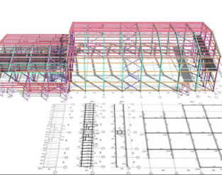


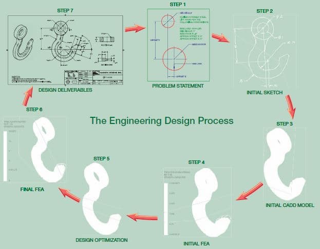

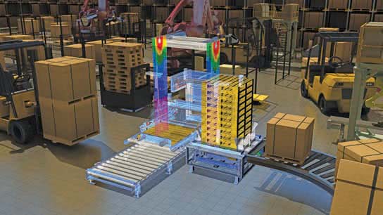
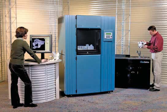
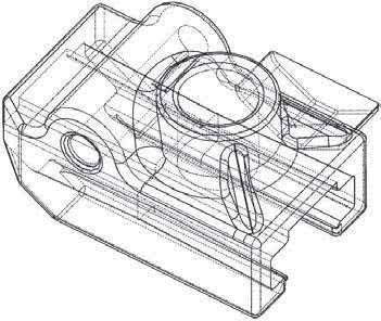
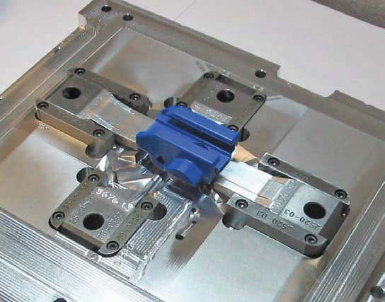
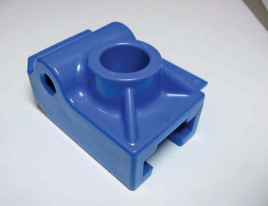
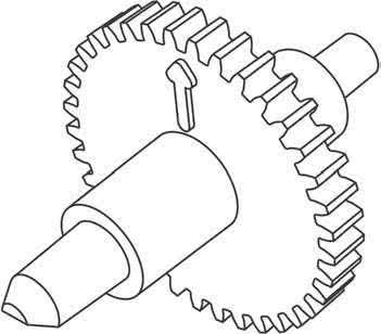
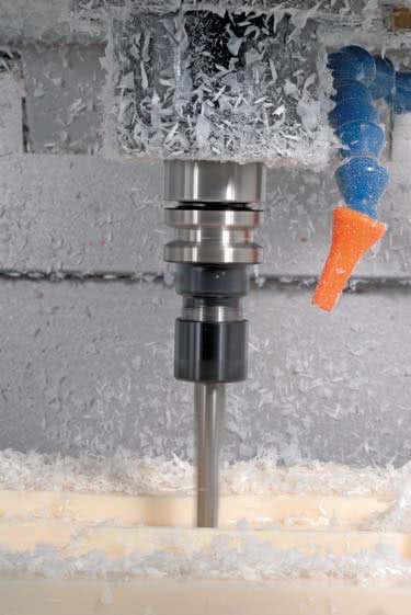
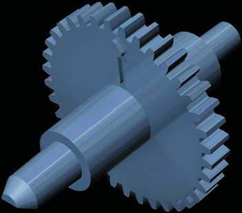

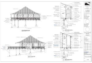

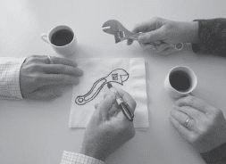
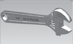
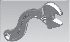
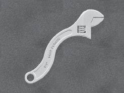 The figure shows the prototype of the new wrench design. The design team tests the prototype in an application similar to what the engineer experienced at home. The prototype worked as expected.
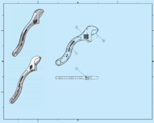 By the next afternoon, the drafter completes the set of working drawings shown in Figure and sends the drawings to the manufacturing department to manufacture and assemble the new product. The manufacturing department needs lead time to design and make the forging dies required to reproduce the parts. Lead time is the time interval between the initiation and the completion of a production process. Forging is the process of shaping malleable metals by hammering or pressing between dies that duplicate the desired shape. The hand-tool company is small, so the drafter is also responsible for creating catalogue art and copy for marketing the product.
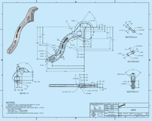 Assembly Drawings and Parts List & Detail drawing of the new wrench body part
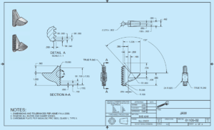 Detail drawing of the new wrench JAW part.
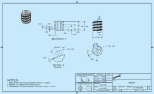 Detail drawing of the new wrench GEAR part.
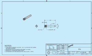 Detail drawing of the new wrench PIN part.
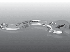 Less than two months after the engineer had the initial idea, the first production run of new wrenches is ready to sell. The figure shows the finished product.