
Individuals with talent, wisdom, vision, and innovative ideas have influenced the history of engineering drawing. Major changes in agriculture, manufacturing, mining, and transport also greatly influenced the evolution of engineering drawing and had an overpowering effect on socioeconomic and cultural conditions between the eighteenth and nineteenth centuries. Recently and more rapidly, computers have become a driving force in the way people create engineering drawings.
Early Drawing Practices

prehistoric humans created images on cave walls and rocks as a form of communication for hunting and gathering societies, to provide ritual or spiritual meaning, and for decoration.
Prehistoric drawings and paintings, known as pictograms, and carvings, known as petroglyphs, show a variety of animals and human shapes. Pictograms and petroglyphs are not engineering drawings, but they do represent early graphic forms of communication. For thousands of years, designers of ancient structures and machines used sketches, drawings, and documents to represent inventions and architecture and help design and distribute information to workers. However, activities such as farming, craft making, and toolmaking, and construction generally followed established standards of the time without the use of formal drawings as a guide. Production was more like a form of art than engineering, and each item was unique.
Early engineering drawings representing machines and buildings appear in the fourteenth and fifteenth centuries. These drawings were generally in the form of pictorial sketches with written descriptions that helped workers understand the intent of the drawings for fabrication or building. Early engineering drawings served as a reference for craft workers to construct a building or manufacture a product. Craft workers viewed the drawings and written descriptions and made interpretations based on their own experience and knowledge of current standard practices. Specific dimensions were not necessary, because each building or machine was different. Early engineering drawings were also an art form used during presentations to the persons who requested the designs.
Engineering Drawing Pioneers
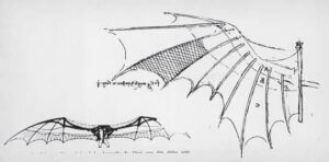
Most early creators of engineering drawings were artists and inventors. Some of the best-known early engineering drawings are the work of Italian Leonardo da Vinci. Leonardo is well known for his art, such as The Last Supper in 1498 and the Mona Lisa in 1507. He was also an inventor who designed machines such as the glider shown in Figure and military equipment such as the giant crossbow. Leonardo’s drawings were those of an artist and were not in the form of engineering drawings. Leonardo’s drawings were pictorial and generally without dimensions. No multiview drawings of Leonardo’s designs are known to exist. Multiview drawings are 2-D drawings of objects organized in views.
Skilled tradespeople worked from the pictorial sketches and representations to construct models of many of Leonardo’s designs. Each machine or device was unique, and parts were not interchangeable. Leonardo was also an early mapmaker. In 1502, Leonardo created a map containing the town plan of Imola, Italy. Authorities commissioned Leonardo as the chief military engineer and architect because of this mapmaking. Arguably, this early work was more artistic than the beginning of engineering drawing, but this work holds a special place in history.
Approximately the same time as Leonardo da Vinci created his drawings, awareness developed that drawings require greater accuracy and dimensions. An early author of architecture and engineering was an Italian man, Leon Battista Alberti. Leon’s writing covered a wide range of subjects, from architecture to town planning and from engineering to the philosophy of beauty. In 1435 and 1436, Leon also wrote two works that explored the need to incorporate more geometry in drawings. Leon also proposed drawings with multiple views rather than the commonly used pictorial drawings.
The importance of using multiview two-dimension drawings was also influenced by the development of descriptive geometry in the work of French philosopher and mathematician René Descartes (1596-1650) and the work of Frenchman Gaspard Monge (1746-1818). René was the inventor of the Cartesian coordinate system, and he founded analytic geometry, the link between algebra and geometry. The Cartesian coordinate system uses numerical coordinates to locate points in space according to distances measured in the same unit of length from three intersecting axes. The Cartesian coordinate system is the basis for establishing points when using CADD today.

Gaspard Monge created a large-scale plan of a town using his own methods of observation and instruments that he designed. As a result, authorities commissioned Gaspard as a drafter and pupil in the practical school of the military institution. Given a project to design a proposed fortress, Gaspard used his geometrical method to create the design quickly. Continuing his research, Gaspard arrived at a graphic method of the application of geometry to construction, now called descriptive geometry. Descriptive geometry is the system of graphic geometry that uses plane projections to describe and analyze their properties for engineering drafting applications.
The Influence of Interchangeability
The Industrial Revolution was a period from the eighteenth to nineteenth centuries when major changes took place in agriculture, manufacturing, mining, and transport. The need for interchangeability in manufactured products became important during the Industrial Revolution. Interchangeability refers to parts manufactured identically within given tolerances. interchangeable parts are produced to specifications that make sure they are so nearly identical that they fit into any product for which they are designed. One part can replace another of the same part without custom fitting. Interchangeability allows easy assembly of new products and easier repair of exist- ing products while minimizing the time and skill required for assembly and repair.
HISTORY OF ENGINEERING DRAWING
The application of interchangeability started with the firearms industry. Before the eighteenth century, gunsmiths made guns one at a time, and each gun was unique. If one component of a firearm needed to be replaced, the entire weapon was sent back to the gunsmith for custom repairs or the firearm was discarded. The idea of replacing these methods with a system of interchangeable manufacture gradually developed during the eighteenth century. Interchangeability was not realized except in special examples until the development of the micrometre in the late 1800s; even then, interchangeability was not easy to achieve. Without the concept of interchangeability, accurate drawings were not necessary. After these advances, engineering drawing began to evolve more rapidly in the nineteenth century.
Drafting Practices and Equipment
Early engineering drawings were often works of art and commonly made with ink. Drafters initially drew using a pencil, T-square, triangles, scales, irregular (French) curves, and drawing instruments such as compasses and dividers. Drafting textbooks as late as the fourth edition of this textbook spent pages describing how to sharpen, hold, and properly use pencils to draw quality uniform lines. Drafters often traced original pencil drawings onto cloth using pen and ink. Drafters always paid skilled attention to lettering quality on drawings. Engineering drafters would use a specific lettering style referred to as vertical uppercase Gothic. Architectural drafters used a more artistic style of lettering that defined their drawings as uniquely related to their discipline. Over the years, various templates and other devices were introduced that allowed drafters to produce consistent quality lettering, although most professional drafters preferred to make quality freehand lettering.
Many architectural drafters used a device called a parallel bar, is a long horizontal drafting edge attached to each side of the table that moves up and down on the table. The parallel bar allows the drafter to draw horizontal lines, and triangles are used on the bar to draw angled lines. During the decades after World War II, drafting equipment suppliers introduced a variety of materials to improve the productivity of the drafting process.
Drawing Reproduction
About the same time as interchangeability became important and engineering drawings were evolving, preserving, and duplicating original drawings became important. There was a need to reproduce drawings easily for distribution to manufacturers or builders, so the blueprint process developed. A blueprint is a contact chemical-printing process of a drawing or other image copied on paper with white lines on a blue background. As drawing reproduction evolved, a diazo process that created blue line copies with a white background replaced the blueprint process. Until recently, all drawing reproductions were commonly referred to as blueprints. Today, offices use printers, plotters, and engineering copiers that use xerography to reproduce CADD drawings. The generic term print has replaced the term blueprint.
Computer-Aided Design and Drafting
During the 1980s and 1990s, CADD rapidly became a technology to take seriously. Companies began considering the power of CADD as computer systems and CADD software developed capabilities and features that made them useful in producing professional drawings. Drafters who had used manual drafting for their entire careers had to face the challenge of converting their artistic skill into drawings created using a computer. This was a difficult challenge for many drafters. Soon schools began teaching drafting technology using CADD. This gave the traditional manual drafters an opportunity to learn the new technology and for new trainees to develop CADD knowledge and skills at the entry-level.
Australian Design & Drafting Services provide excellent service for CAD Design and Drafting. Contact Us for more info.
What are engineering drawings used for?
Engineering drawings serve as the universal language of engineers, architects, and designers. They are used for several purposes:
Communication: Engineering drawings communicate the design intent and specifications to various stakeholders involved in the manufacturing or construction process. This includes engineers, fabricators, machinists, contractors, and inspectors.
Visualization: They provide a visual representation of the final product, enabling stakeholders to understand how the object or structure will look and function.
Documentation: Engineering drawings document the design, dimensions, materials, tolerances, and other critical information necessary for manufacturing or construction. They serve as a reference throughout the lifecycle of the product or project.
Quality Control: Manufacturers use engineering drawings to ensure that the final product meets the required standards and specifications. They serve as a basis for quality control checks and inspections.
Legal and Regulatory Compliance: In regulated industries such as aerospace, automotive, and construction, engineering drawings are essential for complying with legal and regulatory requirements. They demonstrate that the product or structure meets safety, environmental, and other regulatory standards.
Modification and Maintenance: Engineering drawings are used for maintenance, repair, and modification purposes. They provide guidance on how to disassemble, repair, or modify a product or structure without compromising its integrity.
Cost Estimation: By providing detailed information about the design and materials, engineering drawings help in estimating the cost of manufacturing or construction accurately.
What is basic engineering drawing?
Basic engineering drawing refers to the fundamental principles and techniques used to create clear, accurate, and standardized drawings that convey technical information effectively. These drawings serve as a visual representation of objects, components, or structures, and they are essential for communication, documentation, and manufacturing processes in engineering disciplines such as mechanical, civil, electrical, and architectural engineering.
Here are some key aspects of basic engineering drawing:
Orthographic Projection: This is the primary method used to represent objects in engineering drawings. It involves creating multiple 2D views of an object from different perspectives (front, top, side, etc.) to fully describe its shape and features.
Dimensioning: Dimensions are added to engineering drawings to specify the size and location of features accurately. This includes linear dimensions (length, width, height), angular dimensions (angles), and geometric dimensions (tolerances, concentricity, symmetry, etc.).
Drawing Standards: Basic engineering drawings adhere to standardized conventions and symbols to ensure consistency and clarity. Common standards include ASME Y14.5 for dimensioning and tolerancing, ISO 128 for technical drawings, and specific industry standards as needed.
Line Types and Weights: Different types of lines (e.g., continuous, dashed, hidden) and line weights are used to differentiate between different elements of the drawing, such as object lines, dimension lines, and centerlines.
Title Block: Each engineering drawing typically includes a title block containing essential information such as the drawing title, scale, revision history, author, and date.
Symbols and Notations: Symbols and abbreviations are used to represent specific features, materials, processes, and annotations on engineering drawings. These symbols help convey information concisely and universally.
Scale: Drawings may be drawn to scale to represent objects accurately relative to their actual size. Common scales include full scale (1:1), half scale (1:2), and so on.