3D Part Modeling

In recent years, 3D printing has revolutionized various industries, and architecture and construction are no exception. This technological advancement offers numerous benefits that enhance creativity, efficiency, and sustainability in the design and building processes. Specifically, 3D part modeling, a technique used in 3D printing, has enabled architects and constructors to bring more complex, precise, and customized designs to life. In this blog, we will explore the impact of 3D printing on architecture and construction, focusing on how 3D part modeling is transforming the industry.

What is 3D Printing in Architecture and Construction?

3D printing, or additive manufacturing, involves creating three-dimensional objects layer by layer from a digital design. In architecture and construction, 3D printing has proven to be a game-changer, allowing architects to design structures with a level of detail and precision previously unattainable using traditional methods. From 3D part modeling for individual components to printing entire buildings, 3D printing offers new opportunities for customization and cost-efficiency.

3D printing in construction can produce complex shapes, intricate details, and even materials that are more sustainable or optimized for specific environmental conditions. This flexibility helps architects and designers push the boundaries of traditional design, while also minimizing waste and improving construction timelines.

The Role of 3D Part Modeling in Architecture

3D part modeling is a crucial element in the 3D printing process. It involves the creation of a digital 3D model of the parts or components that will be printed. In architecture, this means that every element of a building, from structural supports to decorative features, can be modeled and produced with precision. Some key advantages of 3D part modeling in architecture include:

  1. Customization and Precision With 3D part modeling, architects can create highly customized components tailored to the specific needs of a project. Whether it’s a complex, organic shape for a facade or a detailed structural element, 3D printing can produce components that fit perfectly within a design. Traditional construction methods often require costly adjustments during the building phase, but 3D part modeling eliminates much of this uncertainty.
  2. Efficient Prototyping One of the most significant advantages of 3D printing and part modeling is the ability to rapidly prototype designs. Architects can create detailed models of their concepts within a matter of hours or days, rather than weeks. This speed allows for quicker decision-making, reduces the time spent on revisions, and gives clients a better understanding of how the final project will look.
  3. Design Complexity With traditional construction methods, creating complex or intricate designs is often costly and time-consuming. However, 3D part modeling makes it possible to manufacture highly intricate shapes that would be impossible or prohibitively expensive using conventional construction techniques. Curved walls, geometrically complex facades, and organic architectural forms are no longer out of reach.

How 3D Printing Enhances Construction Efficiency

The construction industry is known for its inefficiencies, from delays and budget overruns to material waste. However, 3D printing is bringing significant improvements to this sector, particularly by optimizing the construction process in several key ways:

  1. Faster Construction Times 3D printing enables faster construction times by allowing for the rapid production of building parts. In some cases, entire structures can be printed in just a few days or weeks, compared to months of traditional construction. This can significantly reduce labor costs and project timelines. In addition, 3D printing can function autonomously, requiring less direct supervision and allowing construction workers to focus on other critical aspects of the project.
  2. Reduced Material Waste Traditional construction methods often involve significant material waste. For example, large quantities of excess concrete are usually poured and discarded when building foundations or walls. However, with 3D printing, material is used more efficiently, as only the required amount is printed, layer by layer. This reduction in waste not only benefits the environment but also leads to cost savings for the project.
  3. Cost-Effective Solutions While 3D printers and the initial setup may require significant investment, the long-term cost savings can be substantial. By reducing material waste, improving construction timelines, and cutting down on labor costs, 3D printing can make construction projects more affordable. Moreover, the ability to use alternative materials, such as recycled plastic or sustainable concrete, further reduces costs and environmental impact.
  4. On-Site 3D Printing An emerging trend is on-site 3D printing, where large-scale printers are brought to the construction site to print structures directly. This eliminates the need for transporting heavy building materials, which can save time and reduce logistical challenges. Moreover, on-site printing reduces the dependency on traditional construction methods, which can be influenced by weather, supply chain issues, or labor shortages.

3D Printing and Sustainable Construction

Sustainability is a major concern in modern architecture and construction, and 3D printing is contributing significantly to greener practices. Through 3D part modeling and printing, architects and builders can incorporate sustainable materials, such as recycled plastic, and optimize structures to reduce energy consumption. By using only the necessary amount of material for each component, 3D printing also significantly reduces waste, making it an eco-friendly alternative to conventional construction methods.

Furthermore, 3D printing allows for the creation of energy-efficient designs, such as buildings that are optimized for natural light or passive cooling, without the constraints of traditional building techniques. For example, intricate facades and insulating walls can be 3D printed to meet specific environmental needs, improving the energy performance of buildings.

Challenges and Future Outlook

Despite the many benefits, there are still challenges that need to be addressed for 3D printing to reach its full potential in architecture and construction. One of the main obstacles is the current limitations in material strength and variety, which may make 3D printing unsuitable for certain large-scale or high-strength structural elements. Additionally, the upfront cost of 3D printers can be prohibitive for some firms, although this cost is expected to decrease as the technology becomes more widespread.

As technology advances and more research is conducted, the possibilities for 3D printing in architecture and construction will continue to expand. The development of new materials and the improvement of 3D printing techniques will enable even more efficient, sustainable, and creative building solutions.

Conclusion

3D printing is undeniably reshaping the architecture and construction industries. Through 3D part modeling, architects and builders are able to create highly customized, precise, and complex designs with reduced waste and faster turnaround times. The ability to prototype quickly, coupled with on-site printing and sustainable materials, is making construction projects more efficient and cost-effective. As the technology continues to evolve, it is likely that 3D printing will play an even more significant role in the future of construction, providing innovative solutions to the challenges faced by the industry today.

AutoCAD Conversion

AutoCAD conversion is essential for companies across various industries, providing a seamless way to transition between file types, improve accuracy, and enhance collaboration on complex projects. In this blog, we’ll cover the key aspects of AutoCAD conversion, its importance, common conversion types, and tips for optimizing the process.

Why AutoCAD Conversion Matters

AutoCAD conversion is the process of transforming design data into compatible formats, ensuring that all stakeholders—engineers, architects, and designers—can access and use the information effectively. Converting files into AutoCAD-compatible formats is essential in maintaining the accuracy and integrity of design data. Whether it’s legacy data or newer file formats, AutoCAD conversion enables organizations to work with historical records, share files with collaborators, and meet project requirements seamlessly.

Common Types of AutoCAD Conversions

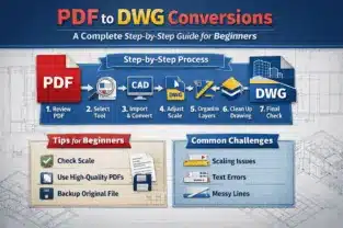
  1. PDF to AutoCAD
    Converting PDFs to AutoCAD is among the most common needs in architecture and engineering. While PDFs provide a snapshot of design documents, converting them into DWG or DXF files allows for editing and modification in AutoCAD. This is especially useful for updating designs, creating as-built drawings, or making revisions.
  2. Image to AutoCAD
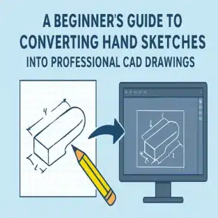
    This process involves converting images (JPEG, PNG, TIFF) into vector-based AutoCAD files. Image conversion is valuable when working with scanned blueprints or hand-drawn sketches that need digital precision. Using tools such as raster-to-vector conversion software can make this process faster and more accurate.
  3. 2D to 3D Conversion
    Many industries are moving toward 3D modeling to create highly detailed and accurate designs. Converting 2D AutoCAD drawings into 3D models provides a more comprehensive view of projects, improving analysis, visualization, and accuracy in construction, manufacturing, and design.
  4. Revit to AutoCAD
    Revit is commonly used for BIM (Building Information Modeling) projects, but there may be situations where a Revit file needs to be converted to AutoCAD for use by team members who work within an AutoCAD environment. This conversion allows for easier cross-platform collaboration.
  5. Point Cloud to AutoCAD
    In industries where laser scanning and 3D measurements are essential, point cloud data can be converted into AutoCAD formats. This is particularly beneficial for renovation projects or when precise site measurements are required.

Key Benefits of AutoCAD Conversion

  1. Enhanced Collaboration
    AutoCAD conversion ensures that data can be shared in a compatible format, enabling teams to collaborate effectively. Cross-disciplinary projects often involve stakeholders using different software platforms; converting files into AutoCAD-compatible formats ensures all team members have access to accurate information.
  2. Data Preservation
    Converting legacy data into AutoCAD formats allows businesses to maintain and preserve historical information, ensuring it’s available and usable in future projects. This is especially important for industries with regulatory requirements for archiving project data.
  3. Improved Accuracy and Consistency
    Manual re-drawing of designs from incompatible formats can lead to errors and inconsistencies. AutoCAD conversion minimizes this risk, ensuring that designs are transferred accurately and efficiently without any loss of detail.
  4. Cost and Time Efficiency
    Automating conversion processes reduces the need for manual rework and accelerates project timelines. Instead of redrawing or creating designs from scratch, conversions allow for immediate use and further development, resulting in significant time and cost savings.

Tips for Successful AutoCAD Conversion

  1. Use Specialized Conversion Tools
    Numerous software tools are available to facilitate AutoCAD conversions. Using dedicated conversion software ensures higher accuracy and reduces the likelihood of errors. Tools such as AutoCAD itself, as well as third-party solutions, can efficiently handle various conversion formats, improving productivity and reliability.
  2. Check for File Compatibility
    Not all file types are directly compatible with AutoCAD. Before converting, verify the compatibility between the source and target file formats to ensure a smooth conversion. This may involve pre-processing or cleaning up files to ensure they translate accurately.
  3. Optimize and Clean Up Files Post-Conversion
    Once a file has been converted, it’s crucial to review and clean it up in AutoCAD. Conversion processes may introduce artifacts or misalignments; therefore, verifying dimensions, line work, and object integrity will ensure the converted file is usable and meets project standards.
  4. Work with an Experienced Conversion Partner
    If your company regularly handles large volumes of conversions or complex projects, consider partnering with an AutoCAD conversion service provider. Professionals with experience in CAD conversions bring expertise that can improve accuracy and efficiency, especially with challenging file types or large data sets.
  5. Document the Process
    Keeping a record of the conversion process, including any challenges or settings used, can be valuable for future conversions. This documentation helps standardize procedures, making the process more efficient and repeatable over time.

AutoCAD Conversion Services: Choosing the Right Provider

For companies looking to outsource AutoCAD conversions, selecting the right service provider is critical. Here are factors to consider:

  1. Experience and Expertise
    Look for providers with proven expertise in AutoCAD conversion and a history of delivering high-quality, accurate conversions. A knowledgeable team will be able to handle complex file formats and provide solutions that fit your project needs.
  2. Service Offerings and Capabilities
    Not all conversion services offer the same capabilities. Check if the provider can handle the types of conversions you need, such as 2D to 3D, image to AutoCAD, or point cloud conversions. It’s beneficial to work with a provider who offers a range of services and flexibility.
  3. Turnaround Time
    In fast-paced industries, turnaround time is crucial. Make sure your service provider can meet your project deadlines and offer quick yet accurate conversions.
  4. Quality Control
    Quality control processes are essential in ensuring that converted files meet industry standards and project requirements. A reputable provider should have quality assurance measures in place, such as double-checking files for accuracy and consistency.
  5. Data Security and Confidentiality
    With sensitive project data involved, ensure your service provider follows strict data security protocols. Ask about their data handling and storage policies to confirm they can safely manage your files.

Conclusion

AutoCAD conversion is more than just transforming files; it’s about enhancing collaboration, preserving data integrity, and improving project efficiency. With the right tools, processes, and partnerships, AutoCAD conversion can streamline workflows and ensure that design data is accessible to everyone who needs it. Whether you’re converting PDF files, transitioning 2D drawings into 3D models, or working with legacy data, understanding the fundamentals of AutoCAD conversion helps companies achieve greater accuracy, save time, and reduce costs.

By following best practices and considering professional AutoCAD conversion services, your organization can maximize the benefits of seamless data compatibility across projects. In a world where design data is essential to project success, effective AutoCAD conversion is a powerful asset that keeps your team aligned and your projects on track.

How do I convert a drawing to CAD?

Converting a drawing to CAD involves taking a physical drawing, an image file, or a PDF, and translating it into a digital format that can be edited within CAD software, like AutoCAD. Here’s a step-by-step guide to help you with this process:
1. Digitize Your Drawing (If on Paper)
Scan the Drawing: If you have a hand-drawn or printed drawing, start by scanning it at a high resolution (300 DPI or higher) to capture all details. Save the scanned image as a PDF, JPEG, or TIFF.
Check the Image Quality: Ensure the scanned file is clear, without any smudges or distortions, as this will impact the quality of your CAD conversion.
2. Choose a CAD Conversion Method
You can convert a drawing to CAD either manually (by tracing) or automatically (using specialized software).
Method 1: Automatic Conversion Using Software
Use Raster-to-Vector Software: Software like AutoCAD (with its PDF import feature), Scan2CAD, or Adobe Illustrator can automatically convert images or PDFs to vector files.
Import into AutoCAD:Open AutoCAD, go to the “Insert” tab, and choose “Attach” to import your PDF or image.
Once attached, select the imported file and use AutoCAD’s “PDF Import” or similar feature to convert the lines into editable vector objects.
Clean Up the Conversion: After conversion, inspect the file for any inaccuracies, overlapping lines, or unneeded elements. Correct any errors and adjust line thicknesses or scales as needed.

How do I convert a CAD file?

Converting a CAD file usually means changing its format (for example, converting a DWG file to a DXF, PDF, STL, or other formats). This can be done directly in CAD software or with specialized conversion tools. Here’s a step-by-step guide to converting a CAD file effectively:
1. Identify the Target Format
Determine the format you need to convert your CAD file to, based on the software you or your collaborators will use. Common conversions include:
DWG to DXF: To maintain compatibility across various CAD programs.
DWG/DXF to PDF: For easy viewing and sharing with clients or stakeholders.
DWG/DXF to STL: For 3D printing.
DWG/DXF to STEP or IGES: For sharing with 3D modeling or CAM software.
2. Use the Built-In Export/Save As Feature in CAD Software
Most CAD programs, like AutoCAD, Fusion 360, and SolidWorks, have built-in options to export or save files in different formats.
AutoCAD:
Open the DWG or DXF file you want to convert.
Go to File > Save As or Export.
Choose the desired format from the dropdown (e.g., PDF, DXF, DWF, etc.).
Adjust any specific options related to the output format (e.g., line weights for PDFs, resolution for STL files).
Save the file in the new format.
Fusion 360:
Open the model or design.
Go to File > Export.
Select the file type you need (e.g., STEP, IGES, STL).
Choose additional settings for format-specific options.
Save or export the converted file.
SolidWorks:
Open the CAD file you want to convert.
Select Save As.
Choose the desired format, such as DXF, STEP, or IGES, from the dropdown menu.
Customize the export settings if needed, then save.

3d printing

Introduction 3D Printing

  • Briefly introduce 3D printing and its transformative impact on industries like automotive, aerospace, healthcare, and product design.
  • Highlight that selecting the right material is crucial for achieving desired project results, durability, and functionality.

1. Understanding the Importance of Material Selection in 3D Printing

  • Explain how different materials affect the strength, flexibility, durability, and aesthetics of printed parts.
  • Note that choosing the wrong material can lead to poor performance, costly mistakes, and delays.

2. Key Factors to Consider When Choosing a 3D Printing Material

  • Purpose of the Print: Describe how the intended function of the part (prototype vs. end-use) influences material choice.
  • Mechanical Properties: Explain why properties like tensile strength, flexibility, and impact resistance matter.
  • Environmental Conditions: Consider factors like temperature tolerance, UV exposure, and moisture sensitivity.
  • Aesthetic Requirements: Discuss how color, texture, and finish impact the visual appeal of the printed object.
  • Budget Constraints: Emphasize balancing cost-effectiveness with material quality.

3. Overview of Common 3D Printing Materials

  • PLA (Polylactic Acid): Explain its popularity for prototyping and low-cost applications.
  • ABS (Acrylonitrile Butadiene Styrene): Mention its strength, impact resistance, and suitability for functional parts.
  • PETG (Polyethylene Terephthalate Glycol): Describe its balance of strength, durability, and ease of use.
  • Nylon (Polyamide): Known for flexibility and strength, ideal for functional parts and wear-resistant applications.
  • Resins: Ideal for detailed models and smooth finishes, often used in dental and jewelry applications.
  • Metal: Used for high-strength, industrial parts; great for aerospace and automotive sectors.

4. Choosing a Material Based on Application Type

  • Prototyping: Suggest PLA, PETG, or resin for prototypes that require aesthetic accuracy without excessive durability.
  • Functional Parts: Recommend ABS, Nylon, or metal for parts that need to withstand stress and impact.
  • Medical or Food-Safe Applications: Discuss biocompatible or food-safe materials like certain FDA-approved resins.

5. Sustainable and Eco-Friendly 3D Printing Materials

  • Introduce eco-conscious options like biodegradable PLA or recycled PETG.
  • Briefly discuss the rise of sustainable materials to meet environmental standards in 3D printing.

6. Tips for Testing and Evaluating Materials

  • Encourage initial testing with small prints to assess a material’s properties.
  • Mention the importance of post-processing techniques for improving material durability and aesthetics.

Conclusion

  • Reinforce that choosing the right 3D printing material directly impacts the success and longevity of the project.
  • Recommend consulting with 3D printing professionals for complex or high-stakes projects to ensure optimal material selection.

How to get perfect 3D prints every time?

How to Get Perfect 3D Prints Every Time
1. Choose the Right Material for Your Project
Different materials, like PLA, ABS, PETG, and nylon, have unique properties and require specific settings.
Choose a material based on your project’s needs (e.g., PLA for easy printing, ABS for durability, nylon for flexibility).
2. Fine-Tune Your Printer Settings
Layer Height: For high-detail prints, use a smaller layer height (e.g., 0.1mm), while larger prints can use a thicker layer (e.g., 0.2mm).
Print Speed: Slow down the print speed for complex geometries or high-quality finishes. Commonly, 40-60mm/s is ideal for most prints.
Nozzle Temperature: Ensure you’re using the correct temperature for the material. Printing too hot or too cold affects layer adhesion and finish.
Bed Temperature: Proper bed temperature minimizes warping, especially with materials like ABS or PETG.
3. Ensure Bed Leveling and Adhesion
Level the Bed: Regularly calibrate and level your print bed, especially if you move the printer or change filaments.
Adhesion Aids: Use aids like glue sticks, painter’s tape, or print surfaces like PEI to improve first-layer adhesion and reduce warping.
4. Control the Environment
Stable Temperature: Print in a controlled, draft-free room. Cold drafts or rapid temperature changes can cause warping and adhesion issues.
Humidity Control: Store filaments in airtight containers with desiccant. Moisture in filament causes popping sounds, bubbles, and weak prints.
5. Use Proper Supports and Overhangs
Overhangs and Supports: Add supports for overhangs over 45 degrees to prevent sagging. Use slicer settings to create detachable supports that don’t affect surface quality.
Bridges: For prints with gaps (bridges), adjust speed, cooling, and infill settings to improve bridging quality without supports.
6. Regularly Maintain Your Printer
Nozzle Cleaning: Clean the nozzle periodically to prevent clogs and ensure smooth filament flow. Replace worn nozzles for consistent performance.
Check Belts and Screws: Tighten loose belts and screws to prevent layer shifting and inaccurate dimensions.
Lubricate Moving Parts: Regular lubrication of moving parts helps the printer operate smoothly and extends its lifespan.

How do I get the best out of my 3D printer?

1. Understand Your Printer’s Capabilities and Limitations
Know Your Printer: Familiarize yourself with your printer’s specifications, such as maximum print volume, nozzle diameter, layer resolution, and compatible materials.
Material Compatibility: Ensure your printer can handle various filaments like PLA, ABS, PETG, or flexible materials. Experiment with different materials to find what works best for specific applications.
2. Keep Your Printer Clean and Well-Maintained
Regular Cleaning: Clean the build plate, nozzle, and extruder regularly. Residue can affect adhesion and print quality.
Nozzle Care: Clear any clogs and replace the nozzle periodically, especially if printing with abrasive filaments like carbon fiber or glow-in-the-dark filaments.
Lubricate Moving Parts: Apply appropriate lubrication to rails, bearings, and threaded rods to keep movement smooth and accurate.
3. Calibrate Your Printer Frequently
Bed Leveling: Keep the bed level for optimal first-layer adhesion. Use manual leveling or auto-leveling features, depending on your printer.
Extruder Calibration: Calibrate the extruder to ensure accurate filament flow, which prevents issues like under- or over-extrusion.
E-Steps Calibration: Adjust E-steps to fine-tune filament extrusion for precise, high-quality prints.
4. Optimize Print Settings in Your Slicer Software
Layer Height: Use lower layer heights (e.g., 0.1mm) for high-detail prints, and higher ones (e.g., 0.2mm) for faster but less detailed prints.
Print Speed: Slower speeds (30-50mm/s) generally yield better detail, while higher speeds (60-80mm/s) can be used for prototypes or low-detail parts.
Retraction Settings: Correct retraction settings minimize stringing. Adjust retraction length and speed based on the material type.
Infill Density: Match the infill density with the part’s intended use. Higher infill gives strength, while lower infill saves material and time.
Cooling Settings: Use appropriate cooling for each material—PLA benefits from high cooling, while ABS requires less to prevent warping.
5. Ensure Proper Filament Storage and Handling
Store Filament Correctly: Moisture affects filament quality, especially for hygroscopic filaments like Nylon and PETG. Store filaments in airtight containers with desiccant.
Dry Filament as Needed: Use a filament dryer if you notice signs of moisture (popping sounds, steam, or uneven extrusion).

2D to 3D Conversion

The demand for 2D to 3D conversion is growing rapidly across industries, from architecture to manufacturing. Converting 2D drawings into accurate 3D models is essential for enhancing visualization, improving design accuracy, and streamlining production. However, even experienced professionals can encounter challenges that may hinder the conversion process. To help you achieve flawless results, we’ve compiled expert tips on how to avoid common pitfalls in 2D to 3D conversion services.

2D to 3D Conversion Service

1. Misinterpreting 2D Data

One of the most frequent mistakes during 2D to 3D conversion is misinterpreting the 2D drawings. In 2D designs, some features may be implied through symbols or lines that don’t translate directly into a 3D model. Ensuring a thorough understanding of the 2D blueprint is critical before conversion.

Tip: Carefully review all 2D documentation and engage with the designer or client to clarify ambiguous areas. If necessary, annotate the 2D drawings with notes on how specific details should be modeled in 3D.

2. Overlooking Scale and Proportions

A lack of attention to scale and proportions during the conversion process can lead to major inaccuracies in the 3D model. Misalignment between the 2D design’s scale and the intended real-world dimensions can result in significant rework.

Tip: Verify that the scale in the original 2D drawing is accurate and consistent throughout the design. During the conversion process, ensure that the proportions remain true to the original scale. This is particularly important for complex projects like architectural designs or precision engineering models.

3. Choosing the Wrong Software

The choice of software for 2D to 3D conversion services plays a crucial role in the accuracy and efficiency of the conversion process. Using incompatible or outdated software can introduce errors and slow down the workflow.

Tip: Select specialized software tailored to your industry’s needs, whether it’s AutoCAD, SolidWorks, Revit, or another platform. Ensure that your software supports seamless integration of 2D and 3D elements. Regularly update your tools to take advantage of the latest features.

4. Failing to Optimize Geometry

Converting a 2D drawing into a 3D model without optimizing the geometry can lead to excessive detail or unnecessary complexity in the final model. Overly complex geometry can cause file size issues and complicate manufacturing processes.

Tip: Simplify the geometry wherever possible while maintaining accuracy. Remove redundant details that do not contribute to the functionality or aesthetic of the final 3D model. Streamlining the design can lead to faster rendering and easier modification.

5. Ignoring Design Intent

A common pitfall is focusing solely on the technical conversion of 2D to 3D while overlooking the overall design intent. Misinterpreting how the 3D model should look or function can lead to a final product that doesn’t align with the project’s objectives.

Tip: Always keep the design intent in mind during the conversion process. Collaborate with stakeholders to ensure that the final 3D model meets the design’s functional and aesthetic goals.

6. Lack of Collaboration with Experts

Attempting to handle 2D to 3D conversion without the guidance of skilled professionals can result in costly errors. Conversion requires a combination of technical expertise, industry-specific knowledge, and precision.

Tip: Work with experienced 2D to 3D conversion services to ensure that the process is handled efficiently and accurately. Professional services can offer valuable insights, reduce conversion time, and eliminate errors that may arise from misinterpretation.

Conclusion

Avoiding these common pitfalls in 2D to 3D conversion can help you achieve flawless results and enhance the overall quality of your projects. By paying attention to detail, selecting the right software, and collaborating with experts, you can streamline the conversion process and produce accurate, functional 3D models. When in doubt, partnering with a reliable 2D to 3D conversion service like ASTCAD can ensure that your project is in capable hands, delivering exceptional outcomes with minimal hassle.

What is the process of 2D to 3D image processing?

The process of 2D to 3D image processing involves converting a flat, two-dimensional image into a three-dimensional representation. This is used in various fields such as medical imaging, animation, gaming, architecture, and more. The process typically follows these steps:

1. Image Collection
The first step is gathering the necessary 2D images, drawings, or scans that will be used for conversion. These could be technical drawings, photos, or medical scans (like MRIs or CTs), depending on the application.

2. Image Preprocessing
Before conversion, the 2D images are cleaned up and optimized for better accuracy in the 3D model. This might include:
Enhancing contrast or brightness to highlight features.
Noise reduction to remove unwanted artifacts.
Edge detection to define boundaries and contours more clearly.
This step ensures the image quality is sufficient for accurate 3D rendering.

What is 3D image processing techniques?

3D image processing techniques involve methods and algorithms that analyze, manipulate, and enhance 3D images or data to extract valuable information or create detailed visual representations. These techniques are widely used in fields such as medical imaging, computer vision, virtual reality, robotics, and scientific research. Below are the key techniques involved in 3D image processing:

1. 3D Reconstruction
This technique converts 2D images or slices into a 3D model by estimating depth and structure. It’s often used in medical imaging (like CT and MRI scans) or computer vision. Common methods include:
Stereoscopic reconstruction: Using two images from different viewpoints to build a 3D model.
Shape-from-shading: Infers depth from lighting and shading in a single 2D image.
Photogrammetry: Creates 3D models from a series of photographs taken from different angles.

2. Point Cloud Processing
A point cloud is a set of data points in 3D space representing the external surface of an object. Processing point clouds involves:
Registration: Aligning multiple point clouds from different angles or positions into a unified coordinate system.
Downsampling: Reducing the number of points while maintaining the object’s shape to optimize processing.
Segmentation: Identifying and separating meaningful parts of the object from the point cloud.

Landscape Development Design

Landscape development design plays a crucial role in transforming outdoor spaces into beautiful, functional areas. Whether it’s a residential garden, commercial space, or public park, well-planned landscape development can enhance aesthetic appeal, increase property value, and contribute to environmental sustainability. In this guide, we’ll cover the essential aspects of landscape development design, highlighting how to create balanced, practical, and visually stunning landscapes.

What is Landscape Development Design?

Landscape development design is the process of planning, organizing, and executing the physical layout of outdoor spaces. It encompasses various elements, such as plantings, structures, pathways, lighting, and water features. The goal is to create outdoor environments that meet both the functional and aesthetic needs of the users while respecting the natural surroundings.

A Landscape Development Design Service provides professional assistance in designing these outdoor spaces. Experts collaborate with clients to develop personalized, sustainable solutions that align with the site’s characteristics, environmental considerations, and desired functionality.

Key Elements of Landscape Development Design

1. Site Analysis and Planning

The first step in landscape development design is to assess the site. This involves analyzing the topography, soil quality, climate, sunlight exposure, and existing vegetation. A thorough site analysis helps determine what can realistically be achieved within the space and sets the foundation for the design process. Understanding the natural layout and constraints is critical in developing a successful landscape.

2. Hardscaping

Hardscaping refers to the non-plant elements in a landscape, such as pathways, patios, retaining walls, and other structures. The right hardscaping elements can add structure and usability to an outdoor space, while complementing the overall design aesthetic. When planning hardscaping, consider materials that blend well with the natural environment and enhance the functionality of the space.

3. Plant Selection and Softscaping

Softscaping involves the living elements of the landscape, including plants, trees, and grass. Selecting the right plants for your design is critical not only for aesthetics but also for sustainability. Native plants are often preferred because they are well-adapted to the local climate and soil, require less water, and promote biodiversity. Additionally, plants should be selected based on their growth patterns, seasonal changes, and compatibility with the overall design theme.

4. Water Features

Adding water elements, such as fountains, ponds, or streams, can elevate a landscape design. Water features introduce a sense of tranquility and movement into the space, while also helping with water management. Proper placement and sizing of water features should be carefully planned to ensure that they fit the scale of the landscape.

5. Lighting

Effective lighting enhances the beauty of a landscape after dark, creating a sense of ambiance and safety. Pathway lights, spotlights for key features, and ambient lighting around seating areas can help highlight the best parts of the design. Lighting can also contribute to the security of the space by illuminating dark areas.

The Role of a Professional Landscape Development Design Service

Hiring a Landscape Development Design Service can make a significant difference in the outcome of your project. Professionals bring expertise in design principles, horticulture, and construction, ensuring that the design is both aesthetically pleasing and functional. A professional service provides the following benefits:

  • Tailored Solutions: Professional landscape designers consider your preferences and lifestyle, creating custom designs that match your vision. They ensure that the space is functional, easy to maintain, and aligned with the natural characteristics of the site.
  • Sustainability: Sustainable landscape development is becoming increasingly important, with a focus on conserving resources and protecting the environment. Experts can help you incorporate water-saving features, energy-efficient lighting, and eco-friendly plant selections.
  • Cost-Effective Execution: With a professional service, you can avoid costly mistakes and delays. Experts can foresee challenges during the planning stage, ensuring that the project runs smoothly and stays within budget.
  • Long-Term Maintenance: A well-thought-out landscape development design will require ongoing care to maintain its beauty and functionality. Many services offer maintenance plans to keep your outdoor space looking its best year-round.

Benefits of Well-Executed Landscape Development Design

Investing in a thoughtful landscape development design offers many advantages, both immediate and long-term. Here are some key benefits:

1. Enhanced Aesthetic Appeal

A well-designed landscape significantly improves the appearance of a property. It can serve as an inviting entryway to a home or a pleasant, serene environment for a commercial or public space. The combination of hardscaping and softscaping elements creates a visually appealing space that complements the architecture.

2. Increased Property Value

A beautifully designed landscape adds value to your property. Curb appeal plays a major role in real estate, and homes or commercial spaces with professional landscape development often command higher market prices.

3. Improved Functionality

Functional outdoor spaces can improve quality of life. Well-designed landscapes provide areas for recreation, relaxation, or work, creating additional space for various activities. For businesses, a well-landscaped outdoor area can also serve as a welcoming environment for clients and employees.

4. Environmental Impact

By incorporating eco-friendly elements like native plants, water-efficient irrigation systems, and sustainable materials, landscape development design can have a positive impact on the environment. Green spaces contribute to air purification, provide habitats for wildlife, and help manage stormwater runoff.

Tips for Successful Landscape Development Design

If you’re planning to undertake a landscape development project, here are a few essential tips to keep in mind:

  • Start with a Vision: Clearly define your goals and preferences for the space. Whether you want a low-maintenance garden, an entertainment area, or a peaceful retreat, having a vision will guide your design decisions.
  • Balance Aesthetics with Functionality: A beautiful landscape should also be practical. Consider how you intend to use the space and prioritize elements that serve both form and function.
  • Plan for the Future: Landscapes evolve over time. Select plants and materials that will age gracefully and require minimal maintenance as the landscape matures.
  • Focus on Sustainability: Incorporate water-wise plants, efficient irrigation systems, and eco-friendly materials to create a landscape that is both beautiful and environmentally responsible.

Conclusion

A well-executed Landscape Development Design can transform any outdoor space into a harmonious blend of beauty and functionality. By considering essential elements such as plant selection, hardscaping, and sustainable practices, you can create a space that enhances the quality of life for its users while adding long-term value to the property. Whether you’re working on a small garden or a large public area, professional Landscape Development Design Services can help you bring your vision to life with expert guidance and practical solutions.

What is a development landscape?

A development landscape refers to the overall context, environment, or ecosystem in which development—whether it be software, infrastructure, or real estate—takes place. It encompasses the various factors, stakeholders, resources, and constraints that influence the development process. The term can be applied in different industries with specific meanings:

1. Software Development Landscape
In software or technology, the development landscape refers to the environment and tools used to create, test, and deploy software applications. This includes programming languages, frameworks, development methodologies (like Agile or DevOps), platforms, version control systems, and deployment environments. Additionally, the landscape also refers to the trends and challenges in the field, such as cloud computing, AI integration, and cybersecurity.
Key components of a software development landscape include:
Tools and Technologies: Programming languages, IDEs, cloud services, etc.
Methodologies: Agile, Scrum, DevOps, etc.
Ecosystems: Platforms like mobile (Android/iOS) or web development.
Trends: AI, microservices, containerization (e.g., Docker), etc.

2. Real Estate or Urban Development Landscape
In real estate or urban planning, the development landscape refers to the physical and regulatory environment in which land or property development occurs. This includes land use policies, zoning regulations, environmental considerations, local economies, and infrastructure planning.
Key components of a real estate development landscape include:
Regulations and Zoning Laws: Rules governing what can be built and where.
Market Conditions: Economic factors that affect demand and pricing.
Environmental Factors: Sustainability, green building practices, and impact assessments.
Community and Stakeholders: Input from local residents, businesses, and governments.

What is design development in landscape architecture?

Design development in landscape architecture is a crucial phase in the overall landscape design process, bridging the gap between conceptual ideas and the final, detailed plans used for construction. It involves refining the initial conceptual design, developing detailed layouts, and selecting specific materials, plantings, and features. This phase ensures that the vision for the landscape is practically achievable, aesthetically cohesive, and aligned with functional requirements.

Here’s a breakdown of what design development entails in landscape architecture:
1. Refining the Conceptual Design
In the conceptual design phase, broad ideas and themes are explored. During design development, these ideas are fine-tuned and brought to a more tangible level. This includes:
Detailed site analysis: Further analysis of the site conditions, such as topography, soil quality, climate, and drainage, to ensure the design is appropriate for the location.
Functional layout: Defining specific spaces and their intended use, such as seating areas, gardens, walkways, water features, and gathering spaces.
Circulation and flow: Determining how people will move through the landscape and ensuring that pathways and access points are functional and accessible.

2. Material and Plant Selection
During the design development phase, the specific materials and plants that will be used in the project are selected. This includes:
Hardscape materials: Choosing the types of paving, stone, wood, or other materials for paths, walls, decks, and structures.
Softscape elements: Selecting the types of trees, shrubs, grasses, and other plantings that will work best for the site’s climate, aesthetics, and sustainability.
Water features and lighting: Determining the types and locations of water features (like fountains or ponds) and outdoor lighting.

Civil Engineering Drawings

Effective communication is the foundation of a successful civil engineering project. One of the most critical tools for conveying design intent, project scope, and technical details to clients is through civil engineering drawings. These drawings serve as a universal language that clients, contractors, and engineers can understand, even if they don’t have a technical background. Improving how you use civil engineering drawings to communicate with clients can greatly enhance the clarity, efficiency, and outcome of your projects.

Civil Engineering Drawings

In this blog, we will explore practical ways to use civil engineering drawings to improve communication and ensure that your clients are fully informed at every stage of the project.

1. Simplify Complex Information for Client Understanding

Clients often lack the technical expertise that engineers possess, so simplifying complex civil engineering drawings without losing essential information is crucial. By using clear labeling, easy-to-read legends, and straightforward annotations, you can help your clients understand the drawings without feeling overwhelmed by jargon or overly detailed technical information.

Best Practices:

  • Use simple and intuitive symbols for key features.
  • Provide a legend or glossary to explain any necessary technical terms.
  • Highlight the most important elements of the design, such as load-bearing structures or critical utilities, so that clients can easily identify them.

2. Incorporate Visual Aids and 3D Models

While traditional 2D civil engineering drawings are important, adding visual aids like 3D models can significantly improve client understanding. Clients often have a hard time interpreting flat drawings, especially when it comes to imagining how a design will look in reality. By supplementing your 2D plans with 3D models, you can offer a more immersive and intuitive way for clients to visualize the final project.

How It Helps:

  • 3D models provide a real-world perspective of the project.
  • Clients can see how different elements fit together in a tangible way.
  • You can walk clients through different design phases or areas of the project virtually, offering better insights and engagement.

3. Ensure Clarity in Revisions and Updates

Civil engineering projects often require changes during the design phase, which means revisions to the drawings. Ensuring clear communication with clients during these updates is essential to avoid misunderstandings. Keeping your drawings well-organized and documenting all revisions ensures that the client remains up to date with any changes that occur throughout the project.

Tips for Clear Communication in Revisions:

  • Use a version control system to track updates and ensure the client is looking at the most current set of drawings.
  • Clearly mark revisions in a different color or with revision clouds, so the client can easily spot the changes.
  • Accompany revised drawings with a brief summary or explanation of the changes, ensuring the client understands the impact on the project.

4. Use Consistent Drawing Standards

Standardizing your civil engineering drawings helps establish a consistent way of communicating across different projects and with various clients. When your clients become familiar with your drawing style and format, they will have an easier time navigating and understanding future projects. This consistency also reduces confusion and ensures that no vital details are overlooked.

Elements to Standardize:

  • Line weights and styles
  • Text fonts and sizes
  • Title blocks and annotations
  • Layers for different types of information (structural, electrical, mechanical)

Establishing and adhering to these standards in all your projects increases professionalism and reduces the chances of miscommunication.

5. Focus on Accurate and Detailed Annotations

Annotations are a key component of civil engineering drawings, offering clients additional explanations of specific design features. Ensuring your drawings have detailed, accurate annotations can make the difference between a client understanding the project and missing out on crucial details.

Best Practices for Annotations:

  • Use concise but informative text to describe important design elements.
  • Avoid over-explaining; stick to what the client needs to know, such as key measurements, materials, and construction techniques.
  • Place annotations close to the elements they refer to, to avoid confusion or misinterpretation.

6. Provide Digital Access to Civil Engineering Drawings

In the digital age, clients appreciate the ability to access project drawings from anywhere, at any time. Offering a civil engineering drawings service that includes digital delivery ensures that your clients can review project designs at their convenience. Additionally, digital drawings allow for easy updates and sharing, making collaboration smoother.

Digital Solutions to Consider:

  • Use cloud-based platforms for sharing drawings, ensuring clients always have access to the latest versions.
  • Provide high-resolution PDFs or CAD files that clients can review and zoom into for detail.
  • Allow clients to leave comments or feedback directly on digital drawings, improving the flow of communication and reducing delays.

7. Schedule Regular Review Meetings

No matter how clear the civil engineering drawings are, face-to-face or virtual meetings are still invaluable for reinforcing communication. Regular review meetings with clients help clarify any points of confusion and ensure that they are aligned with the project’s direction. It also gives you the opportunity to walk clients through the drawings in real-time, providing immediate clarification for any questions or concerns they may have.

Meeting Best Practices:

  • Schedule review sessions after major design milestones.
  • Encourage clients to ask questions during these meetings and clarify any uncertainties they have about the drawings.
  • Use this time to explain any complex aspects of the design that might not be obvious from the drawings alone.

8. Tailor the Drawing Presentation to Your Audience

Clients differ in their technical understanding and involvement in the project. Some clients may prefer high-level overviews, while others may want more detailed information. Tailoring your civil engineering drawings service to meet the needs and preferences of each client ensures better communication and satisfaction.

Steps for Tailoring Your Drawings:

  • Identify the technical level of your client and adjust your communication style accordingly.
  • Provide simplified or summary drawings alongside detailed ones, depending on client preference.
  • Offer to explain certain technical aspects in more detail if a client seems unsure.

Conclusion

Improving communication with clients using civil engineering drawings requires careful consideration of how these drawings are presented and understood. By simplifying complex information, incorporating 3D models, ensuring clarity in revisions, maintaining drawing standards, and tailoring your presentation to the client, you can enhance client communication and project success. Offering a robust civil engineering drawings service that caters to these needs will set your firm apart as a client-focused, reliable partner in engineering design.

What is AutoCAD for civil engineering?

AutoCAD is a widely used software application that plays a vital role in civil engineering. It is primarily used for computer-aided design (CAD) and drafting, allowing civil engineers to create, modify, analyze, and optimize detailed technical drawings and designs for infrastructure and construction projects. AutoCAD’s versatility makes it a cornerstone for the planning and design of roads, bridges, buildings, water systems, and other civil engineering projects.

Key Uses of AutoCAD in Civil Engineering:

Drafting and Drawing Creation: AutoCAD is used to develop 2D and 3D drawings of civil engineering structures. Engineers can create plans, sections, elevations, and detailed layouts with high precision, helping communicate complex project information effectively.
3D Modelling: AutoCAD supports 3D modeling, which enables civil engineers to visualize how the final project will look. This is especially useful for large-scale projects like highways, tunnels, and urban infrastructure.
Site Planning and Design: For tasks like terrain modeling, site planning, and grading, AutoCAD provides engineers with tools to design roads, plot land areas, and analyze topography to ensure accurate and efficient site layouts.
Surveying and Mapping: AutoCAD integrates with surveying equipment, allowing civil engineers to import real-world data such as GPS coordinates, topographical data, and elevation points. This helps in creating accurate site maps and layout plans.

Do civil engineers draw plans?

Yes, civil engineers do draw plans, but this task is often carried out in collaboration with drafting technicians or CAD (computer-aided design) specialists. Civil engineers are responsible for the design and planning of infrastructure projects like roads, bridges, buildings, and water systems. To communicate their design ideas and ensure the proper execution of projects, they create detailed civil engineering drawings or plans.
Types of Plans Civil Engineers Create:
Site Plans: These drawings show the overall layout of a project site, including property boundaries, building locations, access roads, utilities, and landscaping. Site plans are essential for coordinating the placement of all physical components of a project.
Structural Plans: Civil engineers create structural drawings that detail the design of load-bearing elements like beams, columns, and foundations. These plans ensure that buildings, bridges, and other structures can safely withstand the loads they will face.
Grading and Drainage Plans: For land development and roadway projects, engineers design grading plans that show how the ground should be sloped for proper drainage. They also create drainage plans that include water flow management through pipes, culverts, and storm drains.
Utility Plans: These show the layout of essential utilities, including water supply, sewage systems, electrical lines, and telecommunications infrastructure. Civil engineers ensure that utilities are safely and efficiently routed throughout the project area.

Electrical CAD Drafting

Electrical CAD Drafting is a critical component of modern electrical design projects, offering precise layouts and streamlined workflows. However, even with the most advanced tools, troubleshooting issues can arise, potentially derailing project timelines. Whether you’re managing large-scale projects or working on intricate designs, understanding how to troubleshoot effectively can enhance both efficiency and the final output. In this blog, we’ll cover key tips to streamline troubleshooting for Electrical CAD Drafting and ensure better project management.

Electrical CAD Drafting

1. Understand the Scope of Electrical CAD Design

Before diving into troubleshooting specific issues, it’s crucial to have a clear understanding of the project’s scope. Electrical CAD Drafting involves intricate designs, layouts, and schematics for electrical systems. Miscommunication or misunderstanding during the initial project phase can lead to errors later in the drafting process. By clearly defining the project’s needs and ensuring that the design requirements align with the client’s expectations, you’ll minimize confusion and potential setbacks.

Using Electrical CAD Drafting software that supports real-time collaboration can help streamline communication, reducing the risk of misunderstanding between engineers, drafters, and project managers.

2. Regularly Update Electrical CAD Drafting Files

One of the most common issues in Electrical CAD Drafting is working with outdated files. Even small changes to a design, if not updated in the master file, can cause confusion and errors. It’s vital to ensure that your team consistently updates CAD files with the latest revisions, particularly when collaborating across teams or with external clients. Many Electrical CAD Drafting Service providers implement strict version control practices to avoid discrepancies and ensure that everyone works from the most current designs.

Make it a habit to double-check file versions before starting any troubleshooting process, as outdated files often lead to issues that may have already been addressed in more recent revisions.

3. Use Layering to Troubleshoot Electrical CAD Designs

Layering is a fundamental feature in Electrical CAD Design software, allowing drafters to organize different elements of a project. Mismanagement of layers can lead to drafting confusion, such as mixing high-voltage and low-voltage circuits or misplacing wiring details. Proper use of layers allows you to isolate specific parts of the design when troubleshooting, making it easier to locate errors.

Establish a consistent layering structure at the beginning of each project. This structure should be maintained throughout the project lifecycle. If your CAD software allows for layer filters, use them to further simplify the troubleshooting process.

4. Implement Design Rule Checks (DRC) Early

Most Electrical CAD Drafting tools come with built-in design rule checkers (DRC). These can automatically flag issues such as spacing violations, incorrect component placements, and electrical errors. Integrating DRCs into your drafting process early on can help you catch problems before they escalate, saving both time and resources. Electrical CAD Drafting Services that implement DRC checks early in the design process often face fewer delays during project execution.

Use automated tools to perform frequent DRC checks, especially after significant design changes. This ensures the design remains compliant with industry standards and project specifications.

5. Optimize Component Libraries in Electrical CAD Drafting

Having a well-organized component library is essential for Electrical CAD Drafting. Outdated or incorrect components can lead to errors during project execution, and manually searching for updated components wastes valuable time. By maintaining an optimized library of commonly used electrical symbols, connectors, and parts, you’ll simplify the drafting process and reduce the likelihood of errors.

Regularly audit your component library to ensure it remains up-to-date and reflects the latest industry standards. Electrical CAD Design teams should also have shared access to this library to avoid inconsistencies across different parts of the project.

6. Troubleshoot Power and Signal Integrity Issues

One of the key aspects of Electrical CAD Drafting is ensuring that power and signal integrity are maintained throughout the design. Voltage drops, improper grounding, and signal interference are common issues that can derail a project. When troubleshooting, pay particular attention to wire sizing, grounding schemes, and the placement of signal-carrying components.

Tools that simulate electrical systems can be incredibly helpful in identifying these problems before construction begins. By simulating real-world performance, you can ensure that your Electrical CAD Design meets the necessary power and signal integrity requirements.

7. Document Changes and Maintain a Troubleshooting Log

Good documentation is essential for effective project management. When troubleshooting Electrical CAD Drafting issues, keep detailed records of the problems encountered and the steps taken to resolve them. This not only helps in managing the current project but also provides valuable insights for future projects.

A troubleshooting log allows team members to easily track the history of design changes and see which solutions were applied. Electrical CAD Drafting Service providers who maintain thorough records tend to experience fewer recurring issues, as they can refer back to these logs when similar problems arise.

8. Conduct Regular Design Reviews with Stakeholders

Even the most experienced Electrical CAD Drafting teams can overlook critical design flaws. Conducting regular design reviews with stakeholders can help catch potential issues before they become significant problems. These reviews should involve both technical experts and clients to ensure that the Electrical CAD Design aligns with the project’s goals.

During these reviews, stakeholders can offer feedback that might bring new perspectives to the table, helping to identify issues that may not have been apparent during the drafting phase.

9. Leverage Cloud-Based Electrical CAD Drafting Software

Cloud-based Electrical CAD Drafting software offers a host of benefits, including better version control, real-time collaboration, and easy access to files from any location. These features can significantly streamline troubleshooting and project management, especially for teams working remotely or across different locations.

With cloud-based solutions, you can monitor project progress in real-time and ensure that any issues are addressed as soon as they arise, keeping your Electrical CAD Drafting Service running smoothly.

Conclusion

Effective troubleshooting is essential for the success of Electrical CAD Drafting projects. By following these best practices—understanding project scope, using design rule checks, optimizing component libraries, and leveraging modern cloud-based tools—you can manage projects more efficiently while minimizing errors. Adopting a proactive approach to Electrical CAD Design will not only improve your team’s productivity but also lead to better project outcomes.

What is electrical CAD drawing?

Electrical CAD Drawing refers to the creation of technical drawings and schematics used for designing electrical systems. These drawings are produced using Computer-Aided Design (CAD) software, which allows engineers, electricians, and drafters to design, modify, and optimize electrical systems with precision and efficiency. Electrical CAD drawings include diagrams of wiring, circuits, power distribution, lighting layouts, control systems, and other electrical components.

Key Components of Electrical CAD Drawings:
Wiring Diagrams: Visual representation of electrical circuits, showing how wires connect components like switches, outlets, and lighting fixtures.
Single-Line Diagrams: Simplified diagrams that outline the flow of electrical power in a system, showing the connection between equipment with a single line.
Schematic Diagrams: Detailed drawings that represent the internal arrangement of circuits and components.
Panel Layouts: Depicts the physical placement of components such as circuit breakers, fuses, and switches within an electrical panel.
Control Systems: Diagrams illustrating how electrical components interact within automation or control systems.

Benefits of Electrical CAD Drawing:
Precision and Accuracy: Ensures detailed, accurate layouts for complex systems.
Time Efficiency: Streamlines the design process with tools for editing, copying, and organizing elements.
Error Reduction: Automated error-checking and design rule compliance features minimize human mistakes.
Scalability: Allows easy scaling of designs, from small residential setups to large industrial electrical systems.
Collaboration: Facilitates better communication among team members with shareable digital drawings.

Do electrical engineers do CAD?

Yes, electrical engineers often use CAD (Computer-Aided Design) software in their work, particularly for designing and developing electrical systems, layouts, and schematics. While CAD is more commonly associated with fields like architecture and mechanical engineering, it is also crucial in electrical engineering for a variety of tasks.

Common Uses of CAD for Electrical Engineers:
Electrical System Design: Electrical engineers use CAD to design circuits, wiring diagrams, power distribution systems, and electrical panels for buildings, industrial facilities, and machinery.
Schematic Diagrams: They create detailed circuit schematics that show how electrical components are connected and how electrical current flows through the system.
PCB (Printed Circuit Board) Design: Electrical engineers often use CAD software specific to electronics, like ECAD (Electrical CAD), to design printed circuit boards (PCBs) for electronic devices and equipment.
Control System Layouts: For designing automation systems and industrial control panels, engineers use CAD tools to model and layout control components.
Simulation and Testing: Some CAD tools allow engineers to simulate electrical performance, testing for potential issues like short circuits, power loss, or signal interference before implementation.

CAD Software Used by Electrical Engineers:
AutoCAD Electrical: A version of AutoCAD tailored for electrical design, offering libraries of electrical symbols and tools for creating wiring diagrams.
SolidWorks Electrical: A tool for designing complex electrical systems, integrating both 2D schematics and 3D representations.
Eagle: Widely used for PCB design.
OrCAD: Popular for creating electronic circuits and schematics.
ETAP: For power systems modeling and analysis.

Benefits of Using CAD for Electrical Engineers:
Improved Accuracy: CAD tools reduce human error, allowing precise design of electrical systems.
Time-Saving: Automates repetitive tasks like generating schematics or wiring diagrams.
Better Collaboration: CAD files can be shared easily with teams, including other engineers, clients, and contractors.
Enhanced Visualization: Electrical engineers can visualize both 2D and 3D models of their systems, making it easier to identify design issues early.

Steel Structure Rehabilitation

Steel structures are widely used across various industries due to their durability, strength, and flexibility. However, like all materials, steel can deteriorate over time due to factors such as environmental exposure, corrosion, and structural stress. The rehabilitation of steel structures is crucial for extending their lifespan, ensuring safety, and maintaining optimal performance. In this guide, we will explore the key aspects of steel structure rehabilitation, including common challenges, solutions, and the role of retrofitting and rehabilitation services.

Understanding Steel Structure Rehabilitation Deterioration

Steel structures face numerous challenges during their operational life, including corrosion, fatigue, material deformation, and damage from external factors like earthquakes or extreme weather conditions. Without timely intervention, these issues can compromise the integrity and safety of the structure.

Key Causes of Deterioration:

  • Corrosion: Steel is highly susceptible to corrosion, especially in environments with high humidity, salt exposure, or pollutants. Over time, corrosion weakens the steel components.
  • Fatigue: Repeated stress from loads, vibrations, and temperature fluctuations can cause fatigue in steel structures, leading to cracks and failures.
  • Accidental Damage: Impact forces from machinery, vehicles, or even natural disasters can deform or damage steel elements, necessitating rehabilitation of steel structures.

The Importance of Steel Structure Rehabilitation

The rehabilitation of steel structures service plays a crucial role in ensuring the continued performance and safety of existing steel infrastructure. Rehabilitation not only repairs the damage but also reinforces the structure, allowing it to perform optimally under current and future loads. This is particularly important in sectors such as construction, manufacturing, and transportation, where structural integrity is critical.

Methods of Rehabilitation

There are several methods used in the rehabilitation of steel structures, each designed to address specific problems. These methods include:

1. Retrofitting

Retrofitting involves upgrading an existing structure to improve its performance. This process is often used to enhance the load-bearing capacity or to bring structures up to current building codes. Retrofitting and rehabilitation services are especially vital in older structures that were designed with outdated standards.

Common Retrofitting Techniques:

  • Adding steel braces or beams to reinforce existing structures.
  • Installing dampers or shock absorbers to mitigate the impact of vibrations or seismic activity.
  • Strengthening connections between steel components to enhance overall structural integrity.

2. Corrosion Control

Corrosion is one of the primary causes of steel degradation. Proper corrosion control methods are necessary to extend the lifespan of the steel structure. These can include:

  • Surface Treatments: Applying protective coatings like paint, galvanization, or epoxy to shield the steel from moisture and pollutants.
  • Cathodic Protection: A technique that uses electrical currents to prevent corrosion in steel elements submerged in water or exposed to corrosive environments.

3. Replacement of Damaged Components

In cases where steel components are severely damaged, they may need to be replaced. This involves removing the compromised section and installing new steel components. Modern design and drafting services play a crucial role in ensuring precise replacement, making sure the new elements fit perfectly within the existing structure.

The Role of Design and Drafting Services in Rehabilitation

Before starting any rehabilitation project, a comprehensive analysis and design phase is critical. Design and drafting services provide the detailed drawings, specifications, and structural analysis required to successfully execute a rehabilitation project. Accurate design plans ensure that the rehabilitation process addresses the underlying issues and prevents future structural problems.

Key aspects of design and drafting for rehabilitation projects include:

  • Load Analysis: Ensuring that the rehabilitated structure can handle current and future loads, including any increases due to retrofitting.
  • 3D Modelling: Advanced 3D CAD modelling helps visualize the rehabilitation process and identify potential design challenges.
  • Detailed Drafting: Precise technical drawings ensure accurate implementation during the rehabilitation phase, minimizing delays and cost overruns.

Benefits of Professional Rehabilitation Services

Hiring professional rehabilitation of steel structures services offers numerous benefits, including:

  • Enhanced Durability: Proper rehabilitation ensures that the structure remains robust and functional for many more years.
  • Cost Savings: Addressing structural issues early can prevent expensive future repairs or complete replacements.
  • Compliance with Standards: Retrofitting ensures that older structures meet modern safety codes and regulations.
  • Increased Safety: Strengthening structural integrity reduces the risk of accidents and ensures a safe working environment.

Conclusion

The rehabilitation of steel structures is an essential process to maintain the longevity and safety of steel-based infrastructure. By addressing deterioration through techniques like retrofitting and rehabilitation services, corrosion control, and component replacement, professionals can extend the life of these structures and keep them performing optimally. Furthermore, the role of design and drafting services is pivotal in ensuring that the rehabilitation is precise, efficient, and cost-effective.

Whether dealing with corrosion, fatigue, or accidental damage, investing in proper rehabilitation techniques can save time, reduce costs, and ensure the safety of steel structures in any industry.

For more information or to explore our rehabilitation of steel structures service, contact our expert team today and ensure your steel structures remain in top condition for years to come.

what is rehabilitation of structures

Rehabilitation of structures refers to the process of restoring, repairing, or upgrading an existing structure to improve its functionality, safety, and longevity. It involves addressing structural issues caused by deterioration, damage, or outdated design standards, and aims to extend the useful life of the structure while ensuring it meets current codes and regulations.

Key Aspects of Structural Rehabilitation:

Repairing Damage: Fixing areas weakened by corrosion, cracks, or other forms of deterioration.
Strengthening the Structure: Reinforcing elements to support increased loads or enhance resistance to forces like earthquakes or wind.
Retrofitting: Upgrading a structure to improve performance or bring it in line with modern safety and building codes.
Corrosion Control: Implementing protective measures to prevent further degradation, particularly in steel or concrete structures.
Replacing Components: Removing and replacing damaged parts of a structure when repairs are insufficient.

Why is Rehabilitation Necessary?

Safety: Ensures that structures remain safe for use and resistant to potential hazards.
Cost-Efficiency: Rehabilitation can be a more cost-effective solution compared to demolishing and rebuilding.
Preservation: Maintains the historical or functional value of a building or infrastructure.
Environmental Impact: Reduces waste and energy consumption by reusing existing structures rather than constructing new ones.

3D Mechanical Animations

Incorporating CAD data into 3D mechanical animations is a powerful way to visualize complex mechanical designs, improve communication between teams, and create compelling presentations for clients. The process combines detailed CAD models with dynamic 3D animations to simulate real-world operations, enhance product development, and streamline design processes. If you’re working with CAD files and want to bring them to life through animations, here are some essential tips and tricks to ensure smooth integration.

3D Mechanical Animations

Understanding the Role of 3D Mechanical Animations

3D mechanical animations are crucial in illustrating how mechanical systems work. They allow engineers, designers, and stakeholders to see the movement, function, and interaction of components in real-time. These animations can showcase the assembly process, simulate operational conditions, and highlight potential design flaws before manufacturing. Using CAD data for these animations ensures that the model is based on precise, real-world measurements and specifications.

However, transitioning from CAD to animation requires specific knowledge and expertise. Without proper handling, CAD data may lose its accuracy or fail to convey the intended mechanical function. Below are some tips and tricks to help you achieve seamless integration of CAD data into 3D mechanical animations.

1. Choose the Right CAD Format

Before you begin animating, ensure your CAD data is in a format that is compatible with the animation software you’re using. Many animation tools, like Blender, Autodesk Maya, or Cinema 4D, accept formats like IGES, STEP, and STL. These formats preserve the integrity of your 3D models, ensuring that details, measurements, and design elements remain intact during the conversion process.

  • Tip: Export the CAD model in a neutral format like STEP, which ensures a smoother transfer of geometry without compromising the details.

2. Optimize CAD Models for Animation

CAD models are often highly detailed, containing information not necessary for animation, such as excessive internal components or manufacturing details. To avoid overwhelming the animation software and slowing down the rendering process, simplify and clean up the model. Remove unnecessary parts, such as hidden geometries or bolts and fasteners, which won’t be visible in the animation.

  • Tip: Use decimation or retopology tools to reduce the poly count of your CAD model while retaining the necessary details for animation. This will also speed up rendering times.

3. Segment the Model for Better Control

When animating mechanical systems, it’s essential to have control over each part’s movement. Segment the CAD model into separate components so that you can animate them independently. For example, in an engine animation, separate the pistons, crankshaft, and connecting rods to simulate their individual movements.

  • Trick: Group related parts that move together as a single object for more straightforward animation control. This technique reduces the complexity of managing dozens of parts individually while ensuring accuracy in movement.

4. Apply Rigging for Realistic Movement

Once your CAD model is optimized and segmented, it’s time to apply rigging. Rigging is the process of creating a skeletal structure for the model, enabling it to move in a realistic manner. For mechanical animations, this often involves setting constraints on parts to ensure they move within defined limits, such as rotational or linear motion.

  • Tip: Use inverse kinematics (IK) for mechanical systems with connected components, such as robotic arms or linkages. IK ensures that movement at one end of the system correctly influences the entire chain of components.

5. Use Physics Simulations for Realistic Interactions

For highly accurate mechanical animations, integrating physics simulations can bring an extra layer of realism. Physics engines in animation software can simulate gravity, friction, and collisions, which are essential when animating complex mechanical systems. This feature is particularly useful in demonstrating how a product will perform under different conditions or showcasing interactions between parts.

  • Trick: Adjust physics properties such as mass, material, and friction to simulate real-world behavior. This can significantly enhance the credibility of your animation, especially in scenarios where interaction between components is critical.

6. Leverage Keyframes for Smooth Animation

Keyframing is an essential technique in animation that involves setting specific points of movement at certain frames. By establishing keyframes at critical points in your animation, you can control the timing and pace of how the mechanical parts move. This ensures smooth transitions and accurate depictions of how the system works.

  • Tip: For mechanical systems, focus on using keyframes at moments of key mechanical transitions, such as when a valve opens or a piston reaches the top dead center. This allows for precise control over the operation sequence.

7. Add Textures and Materials for Realism

CAD data often lacks the visual aesthetics required for realistic animations. Applying textures and materials to your CAD model enhances its visual appeal and simulates how the mechanical parts will look in real life. Materials like metal, plastic, and rubber can be applied to different parts to differentiate components and give the viewer a clear understanding of the product’s composition.

  • Trick: Use procedural textures that are easy to adjust and apply across multiple parts. This ensures consistency in material appearance, even as you make changes to the model.

8. Ensure Proper Lighting and Rendering

Lighting plays a crucial role in the final appearance of your animation. It highlights the model’s details, materials, and overall movement. When animating mechanical systems, proper lighting can draw attention to specific components or actions. After setting up the lighting, ensure that your rendering settings are optimized to capture all the intricate details of your CAD model.

  • Tip: Use ambient occlusion and shadow rendering techniques to add depth and realism to your animation. These effects create natural-looking shadows that enhance the 3D appearance of your mechanical model.

9. Test and Refine the Animation

Before finalizing your animation, test it thoroughly to ensure that all parts move as expected and that the mechanical interactions are accurate. Watch the animation from multiple angles and fine-tune the keyframes, rigging, and physics properties as needed.

  • Tip: Break the animation into shorter segments for easier testing. This allows you to isolate and address any issues more efficiently.

Conclusion

Incorporating CAD data into 3D mechanical animations requires careful preparation and attention to detail. By optimizing your models, applying rigging, leveraging physics simulations, and testing thoroughly, you can create animations that not only look stunning but also convey accurate mechanical functionality. These tips and tricks will help you deliver high-quality animations that are both visually compelling and technically precise, ensuring that your 3D mechanical animations stand out.

For more information on how we can help you bring your mechanical designs to life, contact our 3D Mechanical Animations Service team at ASTCAD.

Product engineering and development

In today’s fast-paced market, the balance between innovation and feasibility is crucial in product engineering and development. Companies are constantly challenged to innovate while ensuring their designs are practical, cost-effective, and aligned with market demands. This balance is key to delivering successful products that meet customer expectations without overextending resources. Here are some tricks to effectively balance innovation and feasibility in product engineering and development.

1. Incorporate User-Centric Design

Start with the end-user in mind. Understand their needs, preferences, and pain points through research, surveys, and focus groups. By prioritizing user-centric design, product engineering and development services can create innovative solutions that are practical and desirable. This approach reduces the risk of developing features that are novel but irrelevant to the target audience.

2. Leverage Agile Methodologies

Agile methodologies allow for iterative development, which is essential in balancing innovation and feasibility. By breaking the product development process into smaller, manageable sprints, teams can innovate within each phase while continuously testing feasibility. This approach enables quick adjustments and ensures that the final product is both cutting-edge and practical.

3. Employ Cross-Disciplinary Collaboration

Effective product engineering and development often require input from various disciplines, including engineering, design, marketing, and finance. By fostering cross-disciplinary collaboration, teams can merge creative ideas with practical considerations. This collaboration ensures that innovative concepts are evaluated from multiple perspectives, leading to feasible and market-ready products.

4. Utilize Prototyping and Simulation Tools

Prototyping and simulation tools are invaluable in the product engineering and development process. These tools allow teams to test innovative ideas in a virtual environment before committing to full-scale production. By identifying potential issues early, companies can make informed decisions about the feasibility of new features, reducing the risk of costly redesigns later in the process.

5. Focus on Scalability

When developing innovative products, consider scalability from the outset. A product might be innovative and feasible in small quantities, but can it be efficiently produced at scale? Focusing on scalability ensures that the innovation can be practically implemented and sustained as demand grows, making the product more viable in the long term.

6. Conduct Feasibility Studies Early

Before diving deep into product engineering and development, conduct thorough feasibility studies. These studies should assess technical, financial, and market feasibility. By identifying potential roadblocks early, teams can refine their innovative ideas to align with practical constraints, ensuring a smoother development process.

7. Prioritize Modular Design

Modular design allows for flexibility and adaptability in product development. By creating products with interchangeable components, companies can experiment with innovative ideas without overhauling the entire design. This approach also makes it easier to update or improve the product in response to changing market demands, maintaining a balance between innovation and feasibility.

8. Implement a Strong Feedback Loop

Establishing a strong feedback loop is essential in the product engineering and development process. Regularly gather input from stakeholders, including customers, suppliers, and internal teams. This feedback helps refine innovative concepts and ensures they remain feasible throughout the development cycle. Continuous improvement based on feedback leads to a product that is both innovative and practical.

9. Consider Cost-Benefit Analysis

Innovation often comes with increased costs. However, it’s crucial to perform a cost-benefit analysis to determine if the potential benefits of an innovative feature outweigh the additional expenses. This analysis helps in making informed decisions about which innovative ideas are worth pursuing and which might need to be scaled back to maintain feasibility.

10. Maintain Flexibility in Project Management

Flexibility in project management allows teams to pivot when necessary. In product engineering and development, unexpected challenges can arise that threaten feasibility. By maintaining a flexible approach, teams can adapt their strategies, incorporating innovative solutions while staying within practical limits.

Conclusion

Balancing innovation and feasibility is a delicate but essential aspect of product engineering and development. By incorporating user-centric design, leveraging agile methodologies, and fostering cross-disciplinary collaboration, companies can create products that are not only innovative but also feasible and market-ready. Employing these tricks ensures that innovation drives success rather than becoming a stumbling block.

Integrating these strategies into your product engineering and development service can set your company apart in a competitive market, delivering products that resonate with customers and stand the test of time.