Australian Design & Drafting Services create sheet metal part designs using SOLIDWORKS 3D design and Autodesk Inventor, accelerating the design process, saving time and development costs, and increasing productivity.
Australian Design & Drafting Services can:
- Design solid sheet-metal parts and assemblies
- Convert SolidWorks or other CAD models into sheet metal models and allow automatic input of your own bend radius, thickness and K-factor values
- Design around a group of parts in the assembly, ideal for sheet metal enclosures and cases
- Flatten sheet metal designs to analyse manufacturability and create efficient, cost-effective parts
- Produce detailed 2D drawings, STEP, IGES and DXF files for manufacturing
Overview
Since many industries require a wide range of sheet metal parts to house or enclose their designs, Australian Design & Drafting Services takes a flexible design approach. We can:
- Convert SOLIDWORKS or imported CAD models, create original parts, or design around a group of parts
- Generate Base, Edge, Miter, and Swept Flanges
- Generate bends, including Lofted Bends, Sketched Bends, and more
- Use Bend Tables for bend allowance/bend deduction
- Use Forming Tools to create features like ribs, louvres, lances, embosses, and extruded flanges
- Add weld details to sheet metal parts on models or drawings
- Automatically flatten parts to generate flat patterns for manufacturing with bend compensation
Sheet Metal Guidelines We follow while designing Sheet Metal Parts:
Bends
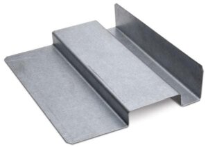
- For the ease of manufacturing, multiple bends on the same plane should occur in the same direction.
- Avoid large sheet metal parts with small bent flanges.
- In low carbon steel sheet metal, the minimum radius of a bend should be one- half the material thickness or 0.80 mm (0.03 inch), whichever is larger.
- Bends specified as angles may be tolerance at plus or minus one-half degree at a location adjacent to the bends.
Curls
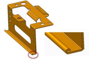
- The minimum radius is two times the material thickness with an opening to a minimum of one material thickness.
- The minimum distance between a curl and the edge of a hole in the radius of the curl plus the material thickness.
- The minimum distance a curl should be from an internal bend is six times the material thickness plus the radius of the curl.
- The minimum distance a curl should be from an external bend is nine times the material thickness plus the radius of the curl.
Dimples
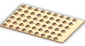
- The maximum diameter should be six times the material thickness, and a maximum depth of one-half the inside diameter.
- The minimum distance that a dimple should be from a hole is three times the material thickness plus the radius of the dimple.
- The minimum distance that a dimple should be from the edge is four times the material thickness plus the inside radius of the dimple.
- The minimum distance that a dimple should be from a bend is two times the material thickness plus the inside radius of the dimple plus the radius of the bend.
- The minimum distance between one dimple and another is four times the material thickness plus the inside radius of each dimple.
Embossments
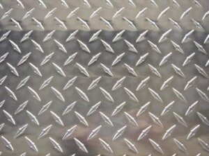
- The maximum depth is proportional to the internal radius or material thickness.
- The maximum depth for a flat embossment is equal to the internal radius plus the external radius.
- The maximum depth for a V embossment is equal to three times the material thickness.
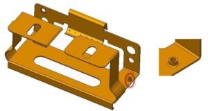
Extruded Holes
- The minimum distance between two extruded holes is six times the material thickness.
- The minimum distance from an extruded hole to an edge is three times the material thickness.
- The minimum distance from an extruded hole to a bend is three times the material thickness plus the bend radius.
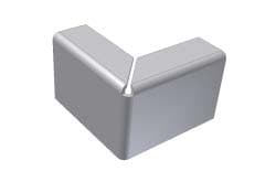
Flanges
- The minimum height of a bent flange is directly related to the material thickness, bend radius, and length of bend.
- The minimum width of a bend relief is one material thickness or 1.50 mm (0.06 inch), whichever is greater.
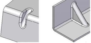
Gussets
- The width and depth, recommended at an angle of 45 degrees, is directly proportional to the radius and material thickness.
- The minimum distance that a gusset should be from the edge of a hole in a parallel plane is eight times the material thickness plus the radius of the gussets.
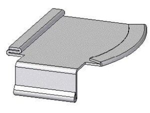
Hems
- The minimum diameter of a teardrop hem is equal to the material thickness, with a return flange height equal to or greater than four times the material thickness, and a minimum opening of 1/4 of the material thickness.
- The minimum diameter of an open hem is equal to the material thickness with a return flange height equal to or greater than four times the material thickness.
- The minimum return flange height of a closed hem is equal to or greater than four times the material thickness (the diameter is zero). NOTE: Closed hems tend to fracture at the bend and cause entrapment of solutions during the finishing process.
- The minimum distance from a hole to hem is two times the material thickness plus the radius of the hem.
- The minimum distance a hem should be from an internal bend is five times the material thickness.
- The minimum distance a hem should be from an external bend is eight times the material thickness.
Holes
- The minimum diameter of a hole should be equal to the thickness of the material or 1.00 mm (0.04 inch), whichever is greater.
- The minimum distance between holes is directly proportional to the size and shape fo the hole feature and the material thickness.
- The minimum distance the edge of a hole should be from a form is three times the material thickness plus the form radius.
- The minimum distance the edge of a hole should be from a bend is two times the material thickness plus the bend radius.
- The minimum distance between a hole and the edge of the material is directly proportional to the size and shape of the hole and the material thickness.
- The minimum distance between the leading edge of a hole through a bend should be equal to the thickness of material plus the bend radius or two times the material thickness, whichever is greater.
Lances
- The minimum width of an open lance is two times the material thickness or 3.00 mm (0.125 inch), whichever is greater, with a maximum length of five times the width.
- The minimum width of a closed lance is two times the material thickness or 1.60 mm (0.06 inch), whichever is greater, and a maximum height of five times the material thickness at a 45-degree angle.
- The minimum distance from a lance to a bend in a parallel plane is eight times the material thickness plus the radius of the bend.
- The minimum distance from a lance to a bend in a perpendicular plane is ten times the material thickness plus the radius of the bend.
- The minimum distance from a lance to a hole is three times the material thickness
Notches
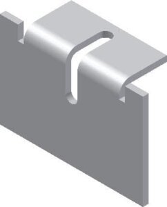
- The minimum width is equal to the material thickness or 1.00 mm (0.04 inch), whichever is greater.
- The maximum length for a straight/radius end notch is equal to five times the width.
- The maximum length for a V notch is equal to two times the width.
- The minimum distance between a hole and the edge of a notch is directly proportional to the size/shape of the hole and the material thickness.
- The minimum distance from a notch to a bend in a parallel plane is eight times the material thickness plus the radius of the bend.
- The minimum distance from a notch to a bend in a perpendicular plane is three times the material thickness plus the radius of the bend.
- The minimum distance beyond the bend on the side edge is equal to the thickness of the material plus the bend radius, or two times the material thickness, whichever is the minimum distance between two notches is two times the material thickness of 3.200 mm (0.125 inch), whichever is greater.
Ribs
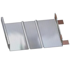
- The maximum inside radius is equal to three times the material thickness, with a maximum depth of the inside radius.
- The minimum distance from a centerline of a rib to the edge of a hole is three times the material thickness plus the radius of the rib.
- The minimum distance a rib should be from an edge in a perpendicular plane is four times the material thickness plus the radius of the rib.
- The minimum distance a rib should be from an edge in a parallel plane is eight times the material thickness plus the radius of the rib.
- The minimum distance a rib should be from a bend perpendicular to the rib is two times the material thickness, plus the radius of the rib, plus the radius of the bend.
- The minimum distance between two parallel ribs is ten times the material thickness plus the radii of the ribs.
Semi-Pierced Hole
- The minimum distance from a semi-pierced hole and a form is three times the material thickness plus the form radius.
- The minimum distance from a semi-pierced hole and a bend is two times the material thickness plus the bend radius.
- The minimum distance between semi-pierced holes is eight times the material thickness.
Slots
- The minimum width of a slot is equal to the material thickness of 1.00 mm (0.04 inch), whichever is greater.
- The minimum distance from the inside surface of a bend to the edge of a slot is directly proportional to the length of the slot, material thickness, and radius of the bend.
- When using slots and tabs, the maximum width of the slot must be greater than the thickness of the tab and the tab length should equal the material thickness.
Tabs
- The minimum width is equal to two times the material thickness or 3.200 mm, whichever is greater, while the maximum length is five times the
- The minimum distance between tabs is equal to the material thickness or 1.00 mm (0.04 inch), whichever is greater.
Counterbores
- The minimum distance between two counterbores is eight times the material thickness.
- The minimum distance from a counterbore to an edge is four times the material thickness.
- The minimum distance from a counterbore to a bend is four times the material thickness plus the bend radius.
Countersinks
- The maximum depth is 3.5 times the material thickness at an angle of the hardware.
- A minimum of 50% contact between the hardware and the countersink is required.
- The minimum distance between two countersinks is eight times the material thickness.
- The minimum distance from one countersink and an edge is four times the material
- The minimum distance from a countersink and a bend is four times the material thickness plus the bend radius.
Welding
- Spot welding should be restricted to joining coplanar surfaces.
- The minimum distance between welds is 10 times the material thickness. Using 20 times the material thickness is ideal.
- The minimum distance between a weld and the edge is two times the diameter of the spot weld.
- The minimum distance from a weld to a form is the spot diameter plus the bend radius.
- Use PEMs instead of threaded inserts.
Plating
- Outside sharp corners receive twice as much plating as flat surfaces.
- Allow for pitch diameters for screw threads, which can increase four times the plating thickness.
- Tapped holes may need to be re-tapped after plating to ensure accuracy.
- Projections accumulate more plating than other areas.
- Recessed areas may be difficult to plate, resulting in little or no coverage.
- Lap-welded joints trap plating solutions. One solution is to raise welds on embossed areas by 0.015 in. (0.3 mm) to allow for flushing and blow-drying between the surfaces.
- Maskings of stampings and fabrications to anodize certain areas are not recommended.
- Design drain holes/vent holes for plating solutions and rinsing.
- Design tabs/holes for attachment to part racks.
Australian Design & Drafting Services has many years of experience designing sheet metal parts and assemblies. We have manufacturing partners for both low and high volume production and would be pleased to discuss your ideas or requirements. Please contact us today to find out how we can help you design and manufacture quality sheet metal parts.