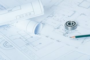
In the fast-paced world of engineering and design, staying at the forefront of technological advancements is crucial. One area that has undergone significant transformation is Engineering CAD Drafting. Computer-Aided Design (CAD) has become the cornerstone of modern engineering, enabling precision, efficiency, and innovation. In this article, we will explore the current trends and innovations in Engineering CAD Drafting, shedding light on how professionals are navigating the ever-evolving landscape.
Trends and Innovations in Engineering CAD Drafting
- Parametric Design and Generative Algorithms:
One of the most noteworthy trends in Engineering CAD Drafting is the integration of parametric design and generative algorithms. This approach goes beyond traditional drafting methods by allowing engineers to create intelligent models that adapt and evolve based on specific parameters. Parametric design not only streamlines the drafting process but also enhances flexibility, enabling quick adjustments and iterations.
Generative algorithms take this a step further, using computational power to explore countless design possibilities. This not only accelerates the initial design phase but also encourages exploration of unconventional and innovative solutions. As technology continues to advance, we can expect further refinement and widespread adoption of these techniques.
- Cloud-Based Collaboration:
The advent of cloud technology has revolutionized how engineering teams collaborate on CAD drafting projects. Cloud-based CAD platforms offer real-time collaboration, allowing multiple team members to work on the same project simultaneously, irrespective of their geographical locations. This has not only improved efficiency but has also facilitated seamless communication among team members.
Additionally, cloud-based solutions provide easy access to project data from various devices, promoting a more flexible and dynamic workflow. The ability to share and access CAD files effortlessly has become a game-changer in the engineering and design industry.
- Integration of Augmented Reality (AR) and Virtual Reality (VR):
The integration of AR and VR technologies is reshaping how engineers perceive and interact with their CAD models. AR and VR allow professionals to visualize designs in three dimensions, providing a more immersive and realistic experience. This not only enhances the design review process but also aids in identifying potential issues before the physical prototype is created.
Moreover, AR and VR technologies enable clients and stakeholders to experience the proposed designs in a more tangible way, fostering better communication and understanding. As these technologies become more accessible, their integration into CAD drafting is expected to become more commonplace.
- Artificial Intelligence (AI) in CAD Drafting:
Artificial Intelligence has made significant inroads into Engineering CAD Drafting, offering intelligent automation and optimization. AI algorithms can analyze design parameters, identify patterns, and even suggest design improvements. This not only speeds up the drafting process but also enhances the overall quality of the designs produced.
Furthermore, AI-powered CAD drafting tools can learn from past projects, making them more adept at anticipating and resolving potential issues. This learning capability has the potential to transform the role of engineers, allowing them to focus more on creative and strategic aspects of the design process.
- Sustainability and Green Design:
With a growing emphasis on sustainability, Engineering CAD Drafting is evolving to incorporate green design principles. CAD software now includes features that allow engineers to assess the environmental impact of their designs, considering factors such as energy efficiency, material usage, and life cycle analysis.
This trend aligns with the global push for sustainable practices in various industries. Engineers are now equipped with tools that not only help create aesthetically pleasing designs but also contribute to a more environmentally conscious approach to engineering.
Engineering CAD Drafting Service
Conclusion:
Engineering CAD Drafting is undergoing a remarkable transformation, driven by technological advancements that promise to reshape the industry. From parametric design and cloud-based collaboration to the integration of AR, VR, and AI, the landscape is evolving rapidly. Engineers and designers who embrace these trends stand to benefit from increased efficiency, enhanced collaboration, and the ability to create more sustainable and innovative solutions. As we navigate the future of Engineering CAD Drafting, it is clear that staying informed and adopting these innovations will be key to success in this dynamic field.
What are CAD drafting services?
CAD drafting services involve the creation, modification, and optimization of technical drawings using computer-aided design (CAD) software. CAD drafting is widely used across various industries such as architecture, engineering, construction, manufacturing, and product design.
These services typically include tasks such as:
Creating 2D Drawings: Drafters use CAD software to create precise 2D drawings of components, assemblies, floor plans, electrical layouts, piping diagrams, and more.
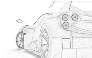
Developing 3D Models: CAD drafters also create three-dimensional models of objects or structures. These models provide a more detailed and realistic representation of the final product or design.
Converting Hand Sketches or PDFs: Sometimes, hand-drawn sketches or PDF documents need to be converted into CAD format for further editing or analysis. CAD drafters can digitize these drawings using CAD software.
Modifying Existing Drawings: CAD drafting services may involve making modifications or updates to existing CAD drawings based on client feedback, design changes, or new requirements.
Technical Documentation: Drafters often create technical documentation such as assembly instructions, part lists, and manufacturing specifications based on CAD drawings and models.
Collaboration and Communication: CAD drafting services facilitate collaboration among project stakeholders by providing accurate visual representations of designs that can be easily shared and reviewed.
How do I get CAD drafting?
here are several ways you can get CAD drafting services:
Hiring an In-House Drafting Team: If you have ongoing drafting needs, especially for large-scale projects or if CAD drafting is a core aspect of your business, you might consider hiring drafters as part of your in-house team. This gives you direct control over the drafting process and allows for close collaboration with other departments.
CAD Software Providers: Some CAD software providers offer drafting services either directly or through their network of partners. If you’re already using a particular CAD software, check if the provider offers drafting services or can connect you with certified professionals who can assist you.
Training In-House Staff: If you have staff members who are interested in learning CAD drafting skills, you can invest in training programs or courses to develop their proficiency. Many online platforms offer CAD training courses suitable for beginners to advanced users.