PROTOTYPING
A prototype is a functional part model of design; it is used as the basis for continuing the production of the final part or assembly. The terms prototype and model are often used interchangeably. Prototypes are used to determine if a new design works as intended. A prototype is commonly used as part of the product design process to enable engineers and designers to explore design alternatives, determine unknown characteristics in the design, finalize part tolerances, confirm customer interest in the design, verify design performance, coordinate with marketing and sales, and test theories before starting full production of a new product. A variety of processes can be used to create a prototype. The processes range from creating a digital model to developing a solid physical model of a part directly from a 3-D CAD model data and to fabricating a model using standard manufacturing processes. A company generally contracts with another company that specializes in developing prototypes quickly and accurately. Some companies have their own prototype development departments. A prototype is generally different from the final production part because special processes and materials are used to quickly create a part that can be used to simulate the actual part.
The development phase of the design process is when a fully functioning prototype model is made that operates at the desired quality level. A physical prototype can be machined, molded, or created using rapid prototyping processes. Parts are assembled into the desired product and then tested to determine if the design meets specifi c product requirements such as weight and performance. The design might have to return to the concept phase for reevaluation if some aspects of the design do not perform as intended or manufacturing process appears to be too costly. After the functioning prototype has been built and tested, drawings are created for continuing to full production of the product.
DIGITAL PROTOTYPING
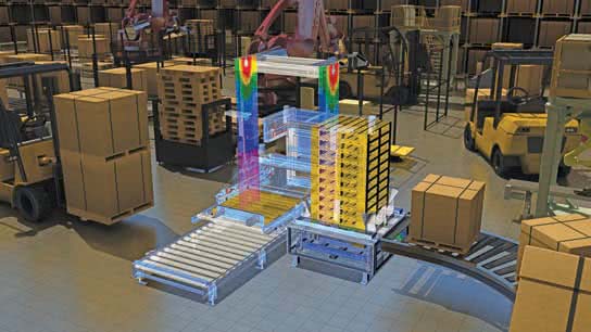
A digital prototype is a computer-generated model or original design that has not been released for production. The most common and useful digital prototype is a 3-D solid model. A solid model digital prototype functions much like a physical prototype, is often just as or even more accurate, and can be subjected to real-world analysis and simulation. Digital prototyping is the method of using CAD to help solve engineering design problems and provide digital models for project requirements. Successful digital prototyping offers several ben-efi ts to the engineering design process. It provides companies with a deeper understanding of product function, enables the simulation of product performance as part of a complete system, offers interactive and automatic design optimization based on requirements, and assists other areas of product development and coordination.
Digital prototyping can support all members of a product development team and help communication. Designers, engineers, and manufacturers use digital prototyping to explore ideas and optimize and validate designs quickly. Salespeople and marketers use digital prototyping to demonstrate and describe products. Depending on product requirements and company practices, digital prototyping can reduce or eliminate the need for physical prototypes, which are often expensive and time-consuming to create and test. The figure shows an example of digital prototyping to model, analyze, simulate, and visualize products in a virtual environment.
RAPID PROTOTYPING
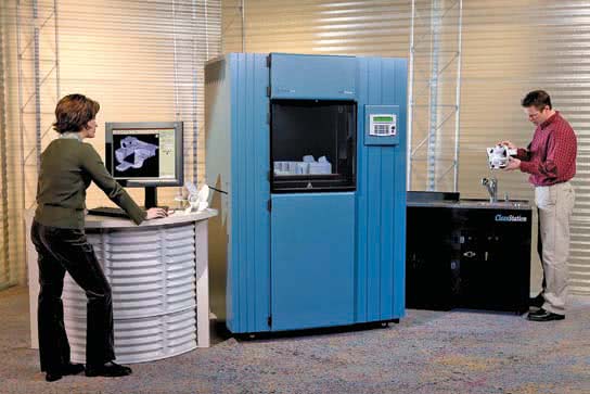
Rapid prototyping is a manufacturing process by which a solid physical model of a part is made directly from 3-D CAD model data without any special tooling. An RP model is a physical 3-D model that can be created far more quickly than by using standard manufacturing processes. Examples of RP are stereolithography (SLA) and fused deposition modeling (FDM), or 3-D printing.
Three-dimensional CAD software such as AutoCAD, Autodesk Inventor, NX, Pro/Engineer, and SolidWorks allows you to export an RP fi le from a solid model in the form of a .stl file. A computer using postprocessing software slices the 3-D CAD data into .005-.013 in. thick cross-sectional planes. Each slice or layer is composed of closely spaced lines resembling a honeycomb. The slice is shaped like the cross-section of the part. The cross-sections are sent from the computer to the rapid prototyping machine, which builds the part one layer at a time. The SLA and FDM processes are similar, using a machine with a vat that contains a photosensitive liquid epoxy plastic and a flat platform or starting base resting just below the surface of the liquid as shown in Figure. A laser-controlled with bi-directional motors is positioned above the vat and perpendicular to the surface of the polymer. The first layer is bonded to the platform by the heat of a thin laser beam that traces the lines of the layer onto the surface of the liquid polymer. When the first layer is completed, the platform has lowered the thickness of one layer. Additional layers are bonded on top of the first in the same manner, according to the shape of their respective cross-sections. This process is repeated until the prototype part is complete.
Another type of rapid prototyping called solid object 3-D printing uses an approach similar to inkjet printing. During the build process, a print head with a model and support print tip create the model by dispensing a thermoplastic material in layers. The printer can be networked to any CAD workstation and operates with the push of a few buttons as shown in Figure.
Rapid prototyping has revolutionized product design and manufacture. The development of physical models can be accomplished in significantly less time when compared to traditional machining processes. Changes to a part can be made on the 3-D CAD model and then sent to the RP equipment for quick reproduction. Engineers can use these models for design verification, sales presentations, investment casting, tooling, and other manufacturing functions. In addition, medical imaging, CAD, and RP have made it possible to quickly develop medical models such as replacement teeth and for medical research.
RAPID INJECTION MOLDING PROTOTYPING
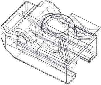
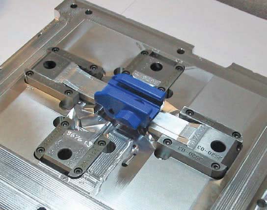
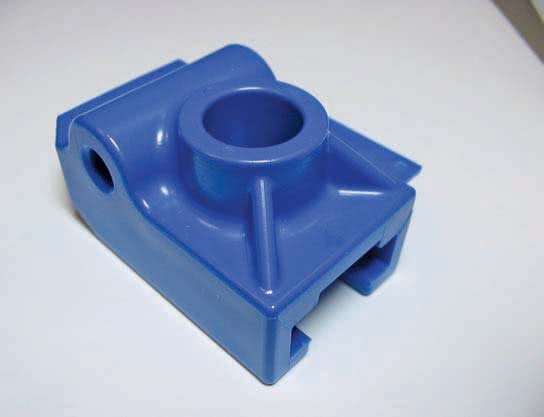
Rapid injection molding is an automated process of designing and manufacturing molds based on customer-supplied 3-D CAD part models. Because of this automation, lead time for the initial parts is cut to one-third of conventional methods. Cost-saving varies with the number of parts being produced, but rapid injection molding can also have a substantial cost advantage in runs of up to thousands of parts. Rapid injection molding produces quality molds using advanced aluminium alloys and precise, high-speed CNC machining. Parts can be molded in almost any engineering-grade resin. The figure shows the 3-D CAD part model, the injection molded part in the mold, and the resulting rapid injection molded part.
SUBTRACTIVE RAPID PROTOTYPING
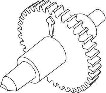
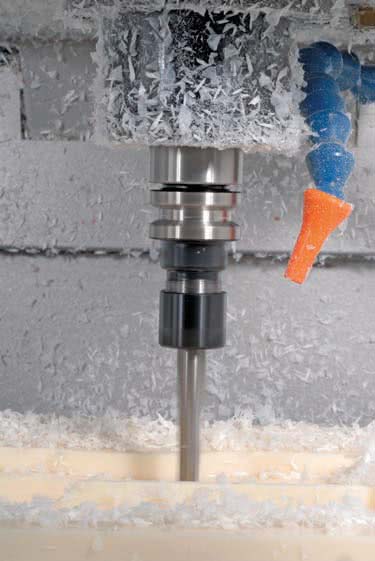
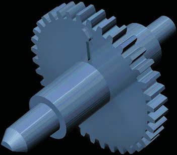
CNC machining of parts has been around for decades, but the use has typically not been applied to short lead-time prototype development. Subtractive rapid prototyping uses proprietary software running on large-scale computers to translate a 3-D CAD design into instructions for high-speed CNC milling equipment. The result is the manufacturing of small quantities of functional parts very fast, typically within one to three business days. A variety of materials, including plastics and metal, can be used with sub-tractive rapid prototyping. The figure shows the 3-D CAD part model, the CNC machining process, and the machined part.
CONVENTIONAL MACHINING PROTOTYPING
Some companies have a machine shop combined with the research-and-development (R&D) department. The purpose of the machine shop is to create prototypes for engineering designs. Drafters generally work with engineers and highly skilled machinists to create design drawings that are provided to the machine shop for the prototype machining. This practice generally takes longer than the previously described practices, but the resulting parts can be used to assemble a working prototype of the product for testing.
Australian Design & Drafting Services provide excellent service for CAD Design and Drafting. Contact Us for more info
What are the prototyping techniques in engineering?
Prototyping is a crucial phase in engineering where initial designs or concepts are transformed into physical models or working versions of a product. There are several prototyping techniques used in engineering, each with its own advantages and applications. Here are some common ones:
3D Printing/Additive Manufacturing: This technique builds objects layer by layer from digital models. It’s highly versatile and allows for complex geometries.
CNC Machining: Computer Numerical Control (CNC) machines use pre-programmed sequences to cut, drill, and shape materials with high precision. It’s suitable for producing functional prototypes from various materials like metal, plastic, or wood.
Injection Molding: Ideal for producing large quantities of prototypes, injection molding involves injecting molten material into a mold cavity. It’s commonly used for plastics.
Vacuum Casting: This technique involves making a silicone mold from a master model and then pouring a resin into the mold. It’s great for producing small batches of prototypes with properties similar to injection-molded parts.
Sheet Metal Prototyping: Sheet metal can be cut, bent, and formed to create prototypes of metal parts or enclosures.
Laser Cutting: Laser cutting uses a high-powered laser to cut through materials like acrylic, wood, or metal sheets. It’s useful for creating flat prototypes or intricate designs.
Foam Modeling: Foam blocks are carved or milled to create rough prototypes of products or parts.
Electronics Prototyping: Breadboarding and soldering components onto perfboards or custom PCBs are common techniques for prototyping electronic circuits.
Rapid Prototyping Techniques: These encompass various fast and low-cost methods like foam core modeling, cardboard modeling, or even LEGO prototyping for quick visualization and concept testing.
Soft Prototyping: Involves using flexible materials like fabrics or elastomers to create prototypes, commonly used in wearable technology or soft robotics.
What is prototype model in engineering?
In engineering, a prototype model is a preliminary version or representation of a product, system, or component that is created to test and validate design concepts, functionality, and performance before full-scale production. Prototyping is an essential step in the product development process as it allows engineers and designers to identify and address potential issues early on, saving time and resources in the long run.
A prototype model can take various forms depending on the nature of the project and the specific requirements. It could be a physical model made from materials such as plastic, metal, or composites, or it could be a virtual model created using computer-aided design (CAD) software or simulation tools.
The primary purposes of creating prototype models in engineering include:
Concept Validation: Prototypes help validate design concepts and ideas to ensure they meet the intended requirements and objectives.
Functionality Testing: Engineers use prototypes to test the functionality and performance of a product or system under real-world conditions. This helps identify any flaws or limitations that need to be addressed.
Iterative Design: Prototyping allows for an iterative design process where changes and improvements can be made based on feedback from testing and evaluation.
User Feedback: Prototypes can be used to gather feedback from potential users or stakeholders, providing valuable insights for refining the design and enhancing user experience.
Cost Reduction: By identifying and addressing issues early in the development process, prototypes help minimize the risk of costly errors and redesigns during later stages of production.
