Creating accurate structural steel shop drawings is a critical step in any steel construction project. These drawings ensure that every steel component is fabricated and installed precisely according to the engineering intent. If you’re new to CAD or steel detailing, this guide will walk you through the process step by step.
What Are Structural Steel Shop Drawings?
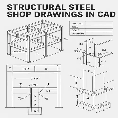
Structural steel shop drawings are detailed and scaled plans used by fabricators to manufacture steel components. Unlike general design drawings, these include precise dimensions, material specifications, welding details, hole locations, and assembly instructions.
They serve as the final blueprint before steel elements are cut, welded, and assembled, and are often required for approval by engineers, architects, and contractors.
Software You Can Use for Structural Steel Shop Drawings
Several CAD programs are commonly used, including:
- AutoCAD
- Tekla Structures
- Advance Steel
- Revit (with extensions)
Each offers different features. For this tutorial, we’ll focus on AutoCAD, a widely used platform that supports 2D drafting and can be adapted for steel detailing.
Step-by-Step Guide: Creating Structural Steel Shop Drawings in CAD
Step 1: Set Up the Drawing Environment
- Open AutoCAD and set the drawing units to millimeters or inches (as per your project standards).
- Create or import a title block that includes project name, drawing number, date, scale, and drafter initials.
- Set up layers for different elements (e.g., beams, columns, annotations, centerlines).
Step 2: Import or Reference the Structural Model
- If you have a 3D model from the design team, insert it as an XREF or import it as a DWG.
- Use this as a base to extract or reference key dimensions and member locations.
Step 3: Identify Structural Steel Elements
- Break down the project into individual parts: columns, beams, base plates, gusset plates, stiffeners, etc.
- Refer to the structural design drawings to determine steel profiles (e.g., W-beams, HSS, angles).
Step 4: Draft Individual Components
- Start with 2D views: top, side, and section views of each component.
- Draw accurate profiles of steel sections using standard dimensions from the AISC or your regional steel handbook.
- Add cutting lengths, hole diameters, and weld symbols.
Step 5: Add Annotations and Labels
- Clearly label each part with:
- Part number or mark
- Material specification
- Quantity required
- Welding instructions
- Use leader lines and callouts to avoid clutter.
Step 6: Add Assembly and Erection Drawings
- Once individual parts are drafted, create assembly drawings showing how parts are connected.
- Include:
- Bolt sizes and patterns
- Weld sizes and types
- Connection plates and stiffeners
- Provide erection sequences and reference the orientation of members.
Step 7: Apply Dimensions and Tolerances
- Use dimension tools to indicate:
- Overall lengths
- Hole centers
- Edge distances
- Weld lengths
- Always apply standard tolerances as per AISC or project specifications.
Step 8: Double-Check for Errors
- Cross-check:
- Member sizes with the structural drawings
- Fabrication feasibility
- Consistency in labeling and material specs
- Use AutoCAD’s Audit and Layer Manager tools to clean up the drawing.
Step 9: Export and Submit for Review
- Save your file in DWG and PDF format.
- Submit to the structural engineer or quality control team for approval.
- After review, incorporate any markups or revisions before final submission to the fabricator.
Tips for Beginners
- Use templates: Create reusable templates for beams, columns, and plates.
- Keep it clean: Use layers and line weights effectively to improve readability.
- Stay organized: Number every drawing sheet and keep a drawing log.
- Refer to standards: Always follow AISC, BS, or IS standards based on your project location.
Why Structural Steel Shop Drawings Are Essential
Without detailed and accurate structural steel shop drawings, fabrication errors, delays, and costly onsite modifications become inevitable. These drawings bridge the gap between engineering intent and real-world execution.
Conclusion
Creating your first structural steel shop drawings in CAD may feel overwhelming, but following a systematic approach ensures accuracy and efficiency. With practice and adherence to industry standards, you’ll be able to produce shop drawings that meet the demands of any steel fabrication project.
For professional assistance in generating high-quality shop drawings, reach out to ASTCAD—your trusted partner for structural CAD drafting services.
What’s the difference between structural drawings and shop drawings?
Structural drawings are created by engineers to convey design intent. Shop drawings are prepared by fabricators and detailers to show how each component will be manufactured and assembled.
Are 3D models required for structural steel shop drawings?
While not mandatory, 3D models help visualize complex connections and are increasingly used to coordinate with BIM (Building Information Modeling) workflows.
How accurate should shop drawings be?
Extremely accurate—down to the millimeter. Any discrepancy can cause misfits during assembly.
Who approves structural steel shop drawings?
Typically, the structural engineer or architect approves shop drawings before fabrication begins.
Can I create structural steel shop drawings without AutoCAD?
Yes, software like Tekla Structures and Advance Steel are more advanced and tailored for steel detailing, but AutoCAD remains a widely accessible tool for 2D shop drawings.