Inspection/Analysis – Comparison to CAD
We move on to downstream applications for 3D models. Before we jump, we need to talk about one more application for scan data. Here we’ll cover how this data can be utilized for quality inspection.
Essential Terminology
- CMM – A mechanical device, Coordinate Measuring Machine with 3D coordinates. Either touch probe is based or non-contact, portable or stationary, or motorized or manual.
- Laser Tracker – The laser beam locates a reflective target against the measured object. The beam reflects the tracker by calculating the distance and angle of the location of the target. Later the Laser trackers come with a great option to get accuracy over more extensive measurement ranges.
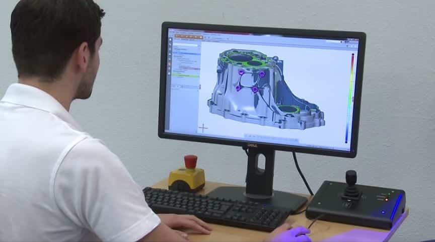
- Color Map: It’s a graphical display for visualising dimensional differences between the measured object shapes. It’s a nominal CAD model to map colour spectrum by indicating location and magnitude.
A HISTORY LESSON
We think the 3D scanning industry comes with something new, where the first 3D digitisers, Coordinate Measuring Machines (CMMs), were built in the 1960s. It’s the entire purpose of development that perform dimensional inspections. In the last few years, checks have been made with the most common uses for 3D scanning and digitising systems.
The engineers at the then-Martin, Marietta, became aware of a company making articulating arms for medical measurements. Later, they began working with the company to develop a portable CMM for inspections in the aerospace industry.
3d Scanning Inspection Analysis
After creating portable CMM, the options for 3D measurement and inspection exploded. The laser scanners added to the movable arms and Laser Trackers were quickly developed. Talking about a few years, portable scan arms have offered standard measurement solutions in major manufacturing firms. It comes from aerospace to automotive and power generation to medical.
TYPES OF INSPECTIONS
- It comes with different types of inspections utilising 3D technologies:
- It’s one fastest and most informative type of inspection called Dimensional Deviation. The CADto Part Inspection covers a typical process Scan Arm. The scan data is compared to the original CAD model, offering a software package showing deviations by a colour map. A variation offer Dimensional Deviation is the Virtual Assembly Analysis. With reference points, the interface datums come with the capability of adding a virtual environment, simulating and identifying how parts fit together in real-world assembly.
- We use the part’s assembly characteristics that apply the mating constraints during assembly. It’s called “reference point fit”, which adds control part movement in each control point. The analysis offer collision in a real-world scenario done virtually.
- It measured the process of being machined. It comes with On-Machine Inspection that allows essential characteristics to be measured and changes the tool to be created. It is typically done using a Portable CMM with probe and scanner. The laser tracker depends on the size of the object that’s being machined.
- Similar to on-machine inspections, it uses real-time inspections for Installation Alignment. It uses significant equipment for laser trackers, PCMM, and more. It offers comprehensive assessments for First Article Inspection (FAI). It involves thoroughly inspecting a physical part against the production drawing dimensions. The typical process comes with portable CMM.
GETTING STARTED
The products take 3D measured data from the portable arms and scanners and perform the inspection analysis. Each capability performs two main inspection types: discreet point dimensional inspection and dense point cloud comparison analysis. The comprehensive capabilities come with GD&T or special case analyses. It’s specialised in certain areas that use multi-scanner integration. It supports the customer in understanding the strengths of each package relative to using specific applications and company requirements. If we perform the project for someone as a service, it’s known as the best software for inspection. Contact us to get more specific packages.
- CAM 2 Measure X (by Faro)
- InnovMetric PolyWorks Inspector
- Geomagic Qualify
- Verisurf
- Rapidform XOV
What you do with your data: inspect, model digitally and reverse engineering. Contact Australian Design & Drafting Services to know more about information.
Can my phone do 3D scanning?
Yes, your phone can perform basic 3D scanning using certain apps that leverage photogrammetry techniques. Photogrammetry works by taking multiple photographs of an object or scene from different angles and then using software to analyze these images and reconstruct the 3D geometry.
There are several apps available for both iOS and Android devices that allow you to capture 3D models using your phone’s camera. Some popular examples include:
Qlone: This app allows you to scan objects using your phone’s camera and built-in AR technology. It provides real-time feedback during the scanning process and offers tools for refining and exporting the resulting 3D model.
3D Scanner App by Laan Labs: This app uses photogrammetry to create 3D models from your phone’s camera. It provides an intuitive interface and supports various export formats for sharing or further editing.
Canvas by Occipital: Canvas is a professional-grade scanning app designed for interior spaces. It allows you to capture 3D models of rooms and environments by walking around with your phone and taking photos from different viewpoints.
Capture by Matterport: Matterport’s Capture app is another professional-grade solution for creating 3D models of spaces and environments. It offers features such as automatic alignment and stitching of photos to generate accurate 3D reconstructions.
What are the basics of 3D scanning?
3D scanning is the process of capturing the shape and appearance of real-world objects or environments to create digital 3D models. Here are the basics of how it works:
Capture: The process begins with capturing data from the real world. This is done using a 3D scanner, which can be a handheld device, a stationary scanner, or even a smartphone equipped with 3D scanning software. The scanner emits various types of energy (like light or lasers) onto the object being scanned and measures how it reflects or reacts to that energy.
Data Acquisition: As the scanner emits energy onto the object, it records the distance to various points on the object’s surface. This data is collected as a point cloud, which is a set of data points in a 3D coordinate system representing the external surface of the object.
Point Cloud Processing: The point cloud data is then processed to remove any noise or artifacts and to align multiple scans if necessary. This step involves cleaning up the data and optimizing it for further processing.
Mesh Generation: Once the point cloud is cleaned up, it can be used to generate a mesh. A mesh is a collection of vertices, edges, and faces that define the surface geometry of the object. There are different algorithms and techniques for mesh generation, and the choice often depends on the specific application and desired level of detail.
Texture Mapping (optional): In some cases, the 3D scanner may also capture color information along with the geometry. This color data can be mapped onto the mesh to create a textured 3D model, which more closely resembles the appearance of the real-world object.
Post-Processing: After the 3D model is generated, it may undergo further post-processing to refine the geometry, improve texture quality, or optimize the model for specific applications. This can include smoothing the mesh, reducing polygon count, or adding additional details.
Exporting: Finally, the completed 3D model can be exported in various file formats for use in different software applications or for 3D printing, visualization, animation, virtual reality, or other purposes.