
Solidworks Electrical 2D and 3D
Create a fast and accurate design by using the electrical cabinet of ducts and rails for routing of wires & cables. It’s mainly used for mounting other components. It primarily represents 2D line art symbols and SOLIDWORKS parts in 3D. The 2D symbol is connected along with manufacturer data by using the database. However, the manufacturer’s database comes with several standard ones. Additionally, one needs to add a custom one and better applicable requirements.
If we look at creating a 3D part, it will adjust the length and profile dimensions which suit our needs better than stock size. Also, to begin with, several rules need to be observed, such as the ability of the software to make the adjustments depending on it.
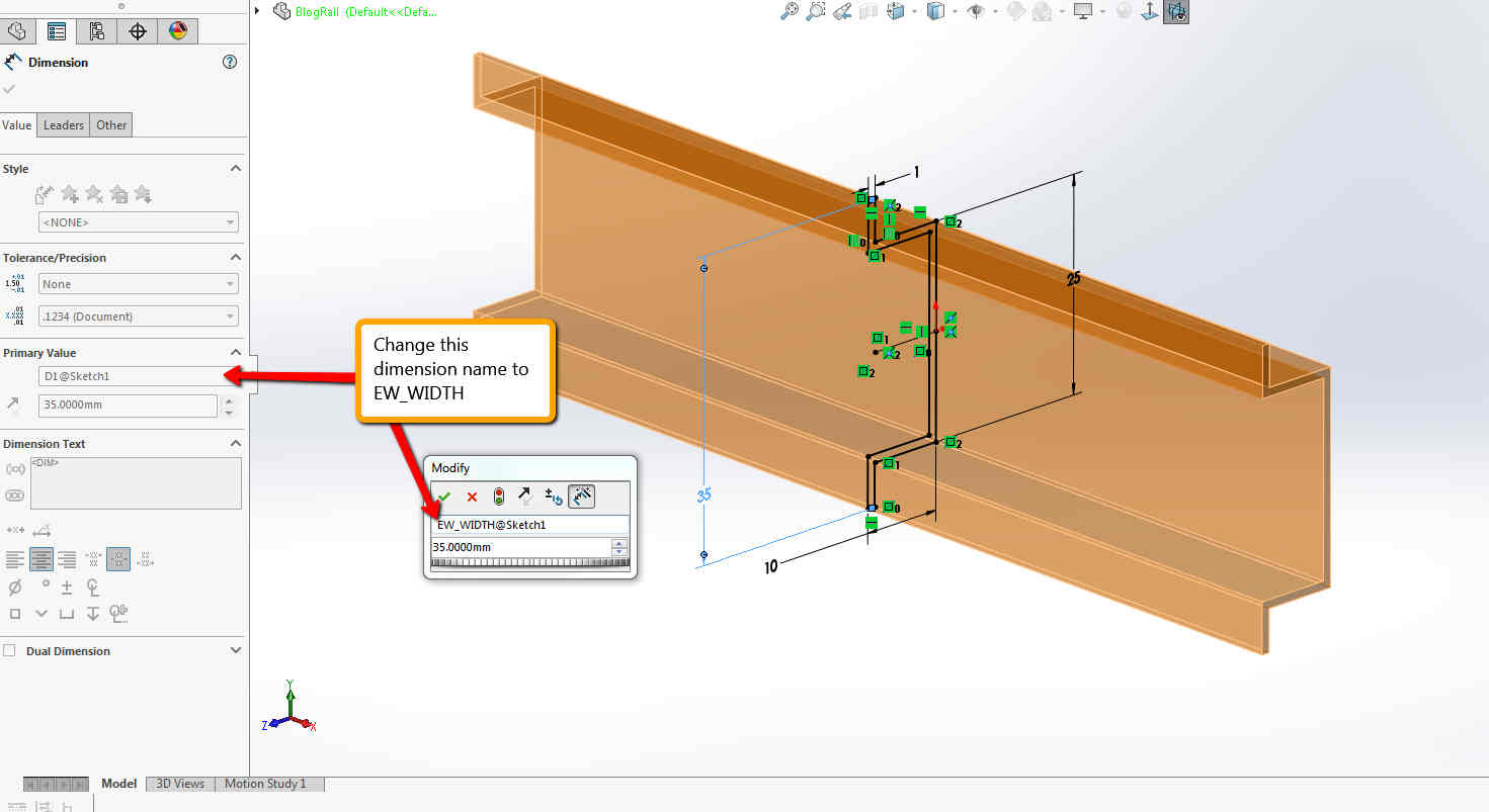
Also, the base configuration is named EW_CONFIG. The name changed by default configured from “Default” to “EW_CONFIG” when the part is first created. The base sketch mainly uses the base extrusion named “EW_SKETCH”.
The base extrusion feature is called “EW_EXTRUDE”. The dimension for the base extrusion is known as “EW_DEPTH”. It is critical to make an adjustable length and use the Change Length command. In our profile sketch, the height and width of the profile should have their dimensions called “EW_WIDTH” and “EW_HEIGHT”.
It adds the format parts on insertion that need mate references named “throwback” with a single face. It mounts other parts and the top and front faces called “trewrail35”. They are mainly used to create the Electrical Component Wizard. Open a new position in SOLIDWORKS by setting the configuration name as “EW_CONFIG”. Also, create a 2D sketch and profile with dimensions for the height and width.
Solidworks Electrical 2D and 3D Services
- SolidWorks Electrical 2D: This component of the software focuses on creating 2D schematics, wiring diagrams, and documentation for electrical systems. It offers a user-friendly interface with various symbols, libraries, and automated features to simplify the design process. Engineers and designers can easily draw electrical schematics and add information like wire numbers, component tags, and connection points. The software also helps in generating bills of materials and other relevant documentation necessary for the electrical system.
- SolidWorks Electrical 3D: Building upon the 2D module, this part of the software allows users to integrate the electrical design into the 3D mechanical model. This synchronization between electrical and mechanical designs enables better collaboration between electrical and mechanical teams and ensures that the electrical components fit seamlessly within the overall product design. The 3D aspect helps in visualizing and resolving potential clashes or interferences between electrical and mechanical elements.
2D and 3D Services
Industries that benefit from SolidWorks Electrical include manufacturing, aerospace, automotive, industrial machinery, electronics, and more. It streamlines the design process, reduces errors, and enhances overall project efficiency.
As with any software, it’s essential to check for updates and new features beyond my last knowledge update in September 2021, as the software might have evolved or received new functionalities since then. For the most accurate and up-to-date information, I recommend visiting the official SolidWorks website or contacting their representatives.
What is SOLIDWORKS electrical 3D?
SOLIDWORKS Electrical 3D is a component of the SOLIDWORKS suite of software products, designed to integrate electrical design with mechanical design in a unified environment. It allows users to create and manage electrical systems and schematics in SOLIDWORKS Electrical and then integrate them directly into their SOLIDWORKS 3D mechanical models.
Here are some key features and functions of SOLIDWORKS Electrical 3D:
Integration with SOLIDWORKS: SOLIDWORKS Electrical 3D seamlessly integrates with SOLIDWORKS CAD software, enabling electrical designers and mechanical engineers to collaborate more effectively. Electrical components and wiring harnesses created in SOLIDWORKS Electrical can be imported directly into SOLIDWORKS 3D models.
Electrical routing: The software provides tools for routing electrical wires, cables, and harnesses within the SOLIDWORKS 3D environment. Users can define routing paths, specify bundle sizes, and ensure proper clearances to avoid interference with mechanical components.
Automatic 3D model creation: SOLIDWORKS Electrical 3D can automatically generate 3D models of electrical components, including connectors, terminals, and cables, based on the schematic design created in SOLIDWORKS Electrical. This streamlines the process of incorporating electrical systems into mechanical assemblies.
Collaborative design: By synchronizing electrical and mechanical designs, SOLIDWORKS Electrical 3D facilitates collaboration between electrical and mechanical design teams. Changes made in either the electrical or mechanical design are automatically updated in the integrated model, ensuring consistency and accuracy across disciplines.
Virtual prototyping: Users can perform virtual prototyping and validation of electrical systems within the SOLIDWORKS 3D environment. This allows designers to identify and resolve potential issues, such as clearance violations or assembly conflicts, before physical prototypes are built.
Bill of Materials (BOM) generation: SOLIDWORKS Electrical 3D enables the generation of comprehensive Bills of Materials (BOMs) that include both electrical and mechanical components. This ensures that all necessary parts are accounted for and ordered correctly during the manufacturing process.
How do I enable 3D in SOLIDWORKS electrical?
To enable 3D in SOLIDWORKS Electrical, you need to ensure that you have the necessary licenses and modules installed, and then follow these general steps:
Install SOLIDWORKS Electrical 3D Module: Ensure that your SOLIDWORKS Electrical installation includes the 3D Module. This module allows you to integrate SOLIDWORKS Electrical with SOLIDWORKS 3D CAD software.
Configure SOLIDWORKS Electrical settings: Open SOLIDWORKS Electrical and go to the settings or options menu. Ensure that the necessary settings related to 3D integration are configured correctly. These settings may include file paths, default templates, and integration preferences.
Set up project properties: Within your SOLIDWORKS Electrical project, verify that the project properties are configured to enable 3D integration. You may need to specify the SOLIDWORKS Electrical 3D project settings, such as the target SOLIDWORKS 3D model template and location.
Create or open a SOLIDWORKS Electrical project: Start a new SOLIDWORKS Electrical project or open an existing one. Ensure that your electrical schematics, components, and wiring are accurately defined within the project.
Integrate with SOLIDWORKS 3D: Once your electrical design is complete, you can integrate it with SOLIDWORKS 3D CAD software. Depending on your workflow and preferences, you can either export the electrical design to SOLIDWORKS 3D or open SOLIDWORKS 3D directly from within SOLIDWORKS Electrical.
Import electrical components into SOLIDWORKS 3D: In SOLIDWORKS 3D, use the appropriate tools or commands to import the electrical components, wires, cables, and harnesses from your SOLIDWORKS Electrical project. This may involve using the SOLIDWORKS Electrical 3D add-in or other integration features.
Manage the 3D model: Once the electrical components are imported into SOLIDWORKS 3D, you can manipulate, position, and route them within the 3D environment as needed. Ensure that the electrical components are properly aligned and integrated with the mechanical design.
Review and finalize the integrated design: Perform a thorough review of the integrated electrical and mechanical design to verify accuracy, clearances, and functionality. Make any necessary adjustments or revisions to ensure that the design meets your requirements.