what is engineering Drawing

Engineering drawing is a common language that describes the process of creating drawings for engineering and architectural application. The engineering drawings work the best and accept standards and format.

It offers an efficient way to communicate and use specific data with adding design intent. The Engineering drawings do not require work and interpret of others’ drawings. It comes with decorative drawings along with using artistic paintings. Using a successful engineering drawing, the user can describe a specific item that the drawing viewer understands without misinterpretation.

One can talk about the term engineering drawing, known for its Drafting, mechanical drawing, mechanical Drafting, engineering drafting, technical Drafting and technical drawing. The Drafting comes with a different graphic language that uses lines, symbols, and other notes to describe objects for an industry like manufacturing or construction. There are technical disciplines that use Drafting, covering civil, architecture, electrical engineering, electronics, piping, manufacturing, and structural engineering.

The term mechanical drafting comes with alternate meanings. The manufacturing industry comes with mechanical Drafting, where the name is derived from mechanisms. The construction industry uses mechanical Drafting in terms of drafting heating, ventilating, and air-conditioning (HVAC) systems. It comes with a mechanical portion of an architectural project.

Whereas if we talk about manual Drafting, it’s a term that describes traditional drafting practice, including pencil or ink onto a medium. It covers paper or polyester film, which supports drafting instruments and equipment. Computer-aided Drafting (CAD) has taken the place of manual Drafting, where the CAD uses computers for drafting. CAD also refers to computer-aided design when computers are used to design.

ENGINEERING DRAWING

Engineering drawings add various concepts that cover instructions, engineering requirements, and proposals. It comes with multiple people and includes different individuals involved with a project. An engineering drawing comes with a complete set of engineering designs that offer data needed to manufacture an item or product. It includes machine parts, consumer products and many more structures.

ENGINEERING DRAWING

The drawing study covers medical instruments that completely describe all geometric features’ location and size. Later, it identifies the characteristics of the part. It mainly uses the material along with manufacturing precision. Also, the medical instrument company uses the drawing to share the document design, which intends to be a part of manufacturing. Let’s say how difficult it can be to understand the engineering drawing.

ENGINEERING DRAWING AUSTRALIA

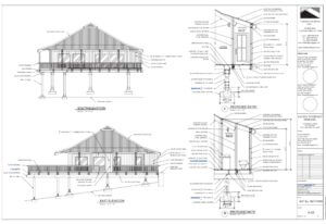
Actually, the engineering drawing comes with an architectural drawing that is mainly used for home re-modelling projects. The drawing uses one sheet in a set of communication with architectural style, size, and location with building features and taking care of the construction methods and materials.

The drawing offers sheets that communicate architectural style, the size and location of building features, and construction methods. The drawings are set to obtain to pay for construction, make permits and legally begin construction. It offers accurate cost estimates that bring impossible and impractical construction without engineering drawings.

Computers In Design and Drafting

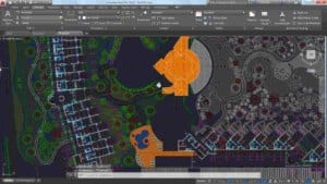
The computers offer revolutionised business along with adding industry process. It covers design and drafting practices with ease. Computer-aided design and drafting (CADD) is a process that uses a computer with CADD software for design and drafting applications. Also, the software is a program that enables a computer to perform specific functions and accomplish a task. Talking CAD is the acronym for computer-aided design, referred to as computer-aided Drafting.

Computer-aided design and computer-aided Drafting offer specific aspects of the CADD process. It mainly uses CADD for the design and drafting process to get accurate and faster CAD design. Several industries mostly use engineering and architecture to get a better outcome. Most engineering industries and educational institutions use manual drafting practices that evolved to CADD.

Whereas CADD allows drafters and designers to produce accurate drawings with neat and matched industry standards. CADD makes architectural drawings with artistic flair lettering and line styles, including a matched appearance with the finest handwork available. In addition to this, CADD drawings come consistently from one person or company to the next. It supports enhancing the ability of designers and drafters, adding creativity to it. It uses new tools such as solid modelling, animation, and virtual reality.

We are an excellent Australian Design & Drafting Service company that provides the best CAD Design and Drafting. Contact Us to get more information.

What is basic engineering drawing?

Basic engineering drawing refers to the fundamental principles and techniques used to create clear, accurate, and standardized drawings that convey technical information effectively. These drawings serve as a visual representation of objects, components, or structures, and they are essential for communication, documentation, and manufacturing processes in engineering disciplines such as mechanical, civil, electrical, and architectural engineering.
Here are some key aspects of basic engineering drawing:
Orthographic Projection: This is the primary method used to represent objects in engineering drawings. It involves creating multiple 2D views of an object from different perspectives (front, top, side, etc.) to fully describe its shape and features.
Dimensioning: Dimensions are added to engineering drawings to specify the size and location of features accurately. This includes linear dimensions (length, width, height), angular dimensions (angles), and geometric dimensions (tolerances, concentricity, symmetry, etc.).
Drawing Standards: Basic engineering drawings adhere to standardized conventions and symbols to ensure consistency and clarity. Common standards include ASME Y14.5 for dimensioning and tolerancing, ISO 128 for technical drawings, and specific industry standards as needed.
Line Types and Weights: Different types of lines (e.g., continuous, dashed, hidden) and line weights are used to differentiate between different elements of the drawing, such as object lines, dimension lines, and centerlines.
Title Block: Each engineering drawing typically includes a title block containing essential information such as the drawing title, scale, revision history, author, and date.
Symbols and Notations: Symbols and abbreviations are used to represent specific features, materials, processes, and annotations on engineering drawings. These symbols help convey information concisely and universally.
Scale: Drawings may be drawn to scale to represent objects accurately relative to their actual size. Common scales include full scale (1:1), half scale (1:2), and so on.

What are engineering drawings used for?

Engineering drawings serve as the universal language of engineers, architects, and designers. They are used for several purposes:
Communication: Engineering drawings communicate the design intent and specifications to various stakeholders involved in the manufacturing or construction process. This includes engineers, fabricators, machinists, contractors, and inspectors.
Visualization: They provide a visual representation of the final product, enabling stakeholders to understand how the object or structure will look and function.
Documentation: Engineering drawings document the design, dimensions, materials, tolerances, and other critical information necessary for manufacturing or construction. They serve as a reference throughout the lifecycle of the product or project.
Quality Control: Manufacturers use engineering drawings to ensure that the final product meets the required standards and specifications. They serve as a basis for quality control checks and inspections.
Legal and Regulatory Compliance: In regulated industries such as aerospace, automotive, and construction, engineering drawings are essential for complying with legal and regulatory requirements. They demonstrate that the product or structure meets safety, environmental, and other regulatory standards.
Modification and Maintenance: Engineering drawings are used for maintenance, repair, and modification purposes. They provide guidance on how to disassemble, repair, or modify a product or structure without compromising its integrity.
Cost Estimation: By providing detailed information about the design and materials, engineering drawings help in estimating the cost of manufacturing or construction accurately.

Engineering designs

Engineering design and drawing offer a broad subject that includes many theories and practices. It has different forms of drawing at the lunch table as a basic sketch of a new product idea drawn on a napkin.

Additionally, the drawing comes in the form of a complex series of models for a new automotive design. It uses hundreds of formal drawings that require the construction of a skyscraper. One could learn the purpose and requirements and create meaningful engineering drawings by using this textbook to study engineering drawing and design. The engineering design applications offer an early explanation along with systematic problem-solving techniques.

WHAT IS THE ENGINEERING DESIGN APPLICATION

We use specific engineering projects or general design along with drafting concepts. The engineering design application mainly uses post guides through a basic example of an engineering design process. It begins with an idea and a basic sketch that ends with manufacturing an actual product.

From an Idea to a Product

The engineering projects and design ideas establish or occur along with an informal setting. For instance, a hand-tool manufacturing company engineer uses a typically adjustable wrench to complete a common home-repair task.

They used the wrench, where the engineers discovered that it was difficult to access a confined location and remove a nut on a piece of equipment. The engineer additionally imagined how the company could manufacture, design, and market a new wrench. We use features that help in making the tool usable in cramped locations. The other day, the engineer and a colleague used the drafting department. The engineer mainly sketches the idea for the new wrench on a napkin by communicating the design to the drafter.

THE ENGINEERING DESIGN APPLICATION fig1.1

The sketch mostly shows the idea of taking the existing tool design that creates a whole new handle adding an ogee or S-shaped curve design. Additionally, the sketch communicates the concept that takes a current tool with creating a fresh hold of an S-shaped curve design.

THE ENGINEERING DESIGN APPLICATION fig1.2a

Later the same day, the drafter would offer the three-dimensional (3-D) solid model files using existing wrench design based on the computer-aided design and drafting (CADD) system.

THE ENGINEERING DESIGN APPLICATION fig1.2b

The user mainly uses drafter copies that revise the existing design based on the engineer’s sketch. The drafter represents the engineer’s new model, who is pleased with the results and requests of a rapid prototype. Rapid prototyping (RP) is a process that creates a physical and functional model from a computer-generated 3-D model. It uses an RP machine, known as a 3-D printer. The RP machines are available that build prototypes from various materials like paper and liquid polymer. The hand-tool company do not have an RP machine. Therefore, the drafter sends files of the design to a company specialising in RP. The engineer and drafter receive a prototype two days later.

THE ENGINEERING DESIGN APPLICATION fig1.3
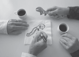
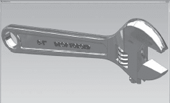
The figure shows the prototype of the new wrench design. The design team tests the prototype in an application similar to what the engineer experienced at home. The prototype worked as expected.

THE ENGINEERING DESIGN APPLICATION fig1.4a
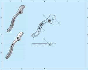
By the next afternoon, the drafter completes the set of working drawings shown in Figure and sends the drawings to the manufacturing department to manufacture and assemble the new product. The manufacturing department needs lead time to design and make the forging dies required to reproduce the parts. Lead time is the time interval between the initiation and the completion of a production process. Forging is the process of shaping malleable metals by hammering or pressing between dies that duplicate the desired shape. The hand-tool company is small, so the drafter is also responsible for creating catalogue art and copy for marketing the product.

detail drawings
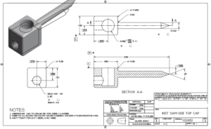
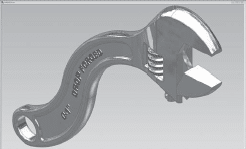
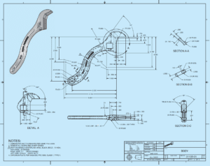
Assembly Drawings and Parts List & Detail drawing of the new wrench body part

jaw part drawings
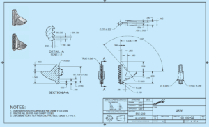
Detail drawing of the new wrench JAW part.

gear part drawings
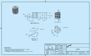
Detail drawing of the new wrench GEAR part.

part drawings for pin
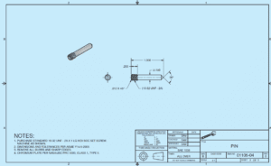
Detail drawing of the new wrench PIN part.

THE ENGINEERING DESIGN APPLICATION fig1.6
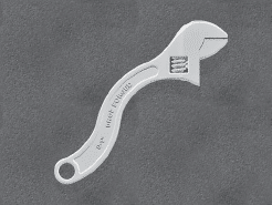
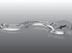
Less than two months after the engineer had the initial idea, the first production run of new wrenches is ready to sell. The figure shows the finished product.

WHAT IS THE ENGINEERING DESIGN APPLICATION

We have the best design team that tests the prototype in an application. It works similar to what the engineer experienced at home. The prototype worked as expected. The drafter supports along with completing the set of working drawings by the next day and sends the drawings to the manufacturing department. It helps to manufacture and assemble the new product. The manufacturing department needs lead time to design and make the forging dies required to reproduce the parts. The Lead time is the time interval between the initiation and the completion of a production process. It helps in the process of shaping malleable metals that presses between dies and duplicate the desired shape. Additionally, the hand-tool company is relatively small. It helps to draft for creating catalogue art and add copy for the product marketing.

Engineering design applications offer numerous benefits that significantly contribute to the efficiency, accuracy, and innovation in the engineering field. Some of the key benefits include:

  1. Efficiency and Productivity: Engineering design applications streamline the design process, reducing the time and effort required to create complex models. They enable engineers to work faster and more efficiently, leading to increased productivity and shorter project timelines.
  2. Cost Savings: By using design applications, engineers can identify potential issues early in the design phase, minimizing costly errors and rework. This proactive approach helps save money throughout the entire project lifecycle.
  3. Improved Design Quality: Engineering design applications allow for more precise and detailed modeling, leading to higher-quality designs. They offer advanced simulation and analysis tools that help engineers optimize their designs and ensure they meet performance requirements and safety standards.
  4. Collaboration and Communication: Design applications often facilitate collaboration among multidisciplinary teams, as multiple engineers can work simultaneously on the same project. It improves communication between team members and stakeholders, enhancing project coordination and reducing misunderstandings.
  5. Innovation and Creativity: These applications foster creativity and innovation by providing engineers with tools to explore various design options and alternatives quickly. They can experiment with different concepts and assess their feasibility before selecting the best approach.
  6. Visualization and Virtual Prototyping: Design applications offer 3D modeling and visualization capabilities, allowing engineers to create realistic virtual prototypes. This enables stakeholders to visualize the final product before physical manufacturing, making it easier to make informed decisions.
  7. Sustainability and Environmental Impact: With the ability to simulate and analyze designs, engineers can evaluate the environmental impact of their projects. They can optimize designs to be more sustainable and eco-friendly, aligning with the growing emphasis on environmental responsibility.
  8. Rapid Prototyping and Manufacturing: Many design applications integrate with 3D printing and computer-aided manufacturing (CAM) technologies. This integration facilitates the seamless transition from design to physical prototype or production, accelerating the manufacturing process.
  9. Regulatory Compliance: Design applications often include features that help engineers adhere to industry regulations and standards. They assist in documenting and validating designs to meet legal and safety requirements.
  10. Continuous Improvement: Engineering design applications often receive updates and improvements, incorporating user feedback and advancements in technology. This ensures that engineers have access to the latest tools and features to continuously enhance their design processes.

Australian Design & Drafting Services provide excellent service for CAD Design and  Drafting. Contact Us for more info

Is engineering design a good career?

Engineering design can be a highly rewarding career for those who enjoy problem-solving, creativity, and innovation. Here are some reasons why it can be a good career choice:
Creativity and Innovation: Engineering design involves creating solutions to real-world problems, which requires creative thinking and innovation. It allows engineers to apply their technical knowledge in unique ways to develop new products, systems, or processes.
Variety of Industries: Engineers can work in a wide range of industries, including aerospace, automotive, electronics, healthcare, and renewable energy, among others. This diversity offers opportunities for specialization and career growth.
High Demand: As technology continues to advance, there is a growing demand for engineers with expertise in design and development. Companies are constantly seeking skilled professionals who can design innovative solutions to stay competitive in the market.
Impactful Work: Engineering design can have a significant impact on society by improving quality of life, advancing technology, and addressing global challenges such as sustainability and healthcare.
Challenging and Rewarding: Designing complex systems or products often involves overcoming technical challenges and working in multidisciplinary teams. Successfully bringing a design from concept to reality can be immensely rewarding.

What are the steps of engineering design process?

The engineering design process typically involves several iterative steps aimed at developing a solution to a problem. While different sources may break down the process into slightly different steps, here’s a commonly accepted framework:

Identify the Problem: Define the problem or need that the design will address. This step involves gathering information, analyzing requirements, and understanding constraints.
Research and Brainstorming: Conduct research to gather relevant data and information. Brainstorm potential solutions and explore various concepts and ideas.
Conceptual Design: Develop initial concepts or sketches based on the research and brainstorming phase. Evaluate different design alternatives and select the most promising ones for further development.
Detailed Design: Refine the selected concepts into detailed designs. This step involves creating technical drawings, specifications, and models to fully describe the proposed solution.
Analysis and Evaluation: Perform analysis and simulations to assess the performance, feasibility, and reliability of the design. This may involve testing prototypes, conducting simulations, or using mathematical models to evaluate different aspects of the design.
Prototype Development: Build prototypes or mock-ups of the design to test its functionality and performance in real-world conditions. Prototyping helps identify any issues or improvements needed before finalizing the design.
Testing and Validation: Conduct testing to verify that the design meets the specified requirements and performs as intended. This may involve various types of testing, such as functional testing, stress testing, and usability testing.
Iterate and Refine: Based on the test results and feedback, refine the design as necessary. Iterate through the design process, making improvements and adjustments until the desired outcome is achieved.
Documentation and Reporting: Document the design process, including all decisions, iterations, test results, and revisions. Prepare reports, technical documentation, and presentations to communicate the design solution to stakeholders.
Implementation and Production: Once the design is finalized and approved, prepare for implementation or production. This may involve coordinating with manufacturers, suppliers, and other stakeholders to bring the design to fruition.
Maintenance and Support: After the design is implemented or deployed, provide ongoing maintenance and support as needed. Monitor the performance of the design and address any issues that arise during operation.

Hire the Right Architect

There has been a new trend in CAD designing world for a 3D modelling for complex design and CAD design platform has evolved so much that 2D drawings become the by-product of 3D modelling.

hire architect brisbane sydney

2D drawings are easy to generate but engineers prefer 3D models for complex applications and design generation. When both are easily achievable, they also are a choice of avoiding catastrophe in the longer run. It basically demands foresight to decide and avail a smooth function of fabrication part of the engineering project and business applications on later stages. Engineering documentation is at the heart of the long, storied history of technical draftsmanship. The objective back then is no different from today’s challenge: represent an engineering design in the most accurate and concise way possible. Distilling the 3D reality we live in onto sheets of paper involved a carefully considered system of dimensioning and orthographic projections. These days, they might be referred to as 2D Drawings (which is a redundant term if you think about it). The system worked then and it works now. Those who are well-trained in these classical methodologies have difficulty understanding why there should be anything else. Why fix what ain’t broke?

To think that 2D drawing has been trashed out with the advent of 3D CAD modelling is far from reality. 2D drafting still has a very prominent place amongst the industrial product designers, and they have their own reasons for it.

2D is the best option when you are facing tight deadlines and the designs are to be developed for a single component or a single part. Basic geometries are easy to generate in 2D CAD sketching tools and are quick. They are intriguing when the drawings do not need any functionalities of 3D and require less space. A designer of any skill sets can easily work with 2D CAD and nearly any desktop will support 2D drafting.

For a crystal clear usage, engineers still use 2D drafts for fabrication drawings, plans, elevation, sectional drawings and shop floor drawings for fabrication. In fact, it is quite surprising that approximately 30% of engineering design firms and design engineers still use paper to design the initial concept sketched and then resort to 2D CAD for digitization.

Despite these benefits, there are a few drawbacks of using 2D. When sectional views are generated in 2D, updating them is time-consuming and also prone to errors. Also, 2D CAD software does not have rendering capabilities. This means, it involves an additional step to export and convert designs into 3D models before rendering.

So for a fact, just to save time, you are doing two more steps, exporting and converting before any other action is being taken- literally two for one. It reduces productivity and lengthens the designing cycle. For these reasons, industry-wide shift to 3D modelling is witnessed among mechanical and industrial product design engineers.

In contrast, the classic engineering drawing is fraught with limitations:

  • Interpretation Issues: A properly executed drawing shouldn’t be subject to misinterpretation, but that skill is starting to become something of a lost art. Unclear depictions can be problematic (i.e. which surface did that leader line touch?). More disturbingly, errors can easily escape detection. Sure, most of that can be mitigated with carefully defined GD&T, but that too seems to be a fading skill. PMI improves upon these limitations by clearly associating surfaces and endpoints and providing validation that such dimensions do indeed make logical sense.
  • Manual Inspection: Drawings necessitate reinterpretation by humans on the other side of the manufacturing lifecycle. It’s another way to introduce error: the botched inspection. PMI sets the stage for automated inspection, accelerating manufacturing processes while simultaneously improving quality.
  • Time is Money: This is where drawings go for the BRAINS… Simply put, in today’s constantly accelerating demand to crank out the engineering in less time, drawings just take too long. Increased market pace demands more efficient processes. An engineer who’s spent considerable time defining a model, shouldn’t have to spend much longer documenting it. The days of modelling something then throwing it over a fence to lay it out are over. These two aspects of the design must occur simultaneously, and this ultimately is only possible with the model-based definition.

3D Models: Make a three-way profit

As business needs became bigger, design cycles were required to get shorter and engineering lead time needed to get easier and without errors; this is when more and more engineers started resorting to 3D CAD software. The advantage of using 3D CAD over 2D CAD is that it reduces the design cycle time to almost half and gives a competitive advantage to designers as well as fabricators by accommodating alterations, much fasters.

Another takeaway with 3D CAD is that it offers excellent workaround while generating rapid prototypes. And with additive manufacturing gaining momentum over traditional manufacturing practices, 3D CAD is the way to adapt to easily transform designs into tangible products.

Since additive manufacturing is a process that eliminates material cutting, it has a dramatic control over scrap produced. This is one among many reasons why this phenomenon has gained traction for every fabricator in any industry – be it industrial sheet metal tools, automotive, building products, furniture or any other that one can think of.

Such a paradigm shift makes it even more important than ever to adopt 3D CAD and drop 2D drafting process for saving material, directly targeting to increase their profits and connects the digital thread opportunity directly with the designs.

2D Drawing or 3D Model platform for CAD Designing

Other than these three major benefits, 3D CAD usually offers more functionality to the user. These functionalities encompass 3D arrays, special views, referencing and much more. But at times these are too many for generating basic part models like line-types, line-weights, and other form features are good to go. In such times, it feels that 2D drawings should be preferred instead of 3D.

Also because since 3D CAD is advanced, licensing is much expensive and renewing it each time the software company rolls-out new version, [not to mention it happens almost every year] it costs heavily to designers. Thus, it is much needed to weigh your needs of design requirements and analyze the cost you are paying for it.

By now, you must have realized that, on the contrary to popular belief, there will be times when you’ll find 2D CAD to be the need of the hour and not 3D models. While during the other times, you’ll find your designing world revolving in the three dimensions of 3D CAD models, whatever be your need – fabrication, design intent clarity or profits – to avoid catastrophe and binge working at the last moment. The hitch is that you select the one that addresses most of your needs since there isn’t any single CAD system that will address all your design and fabrication needs.

Which is better AutoCAD 2D or 3D?

The choice between AutoCAD 2D and 3D depends on your specific needs and the nature of your projects. Here’s a breakdown to help you decide:
AutoCAD 2D:
Best for projects that primarily involve drafting and design in two dimensions.
Ideal for creating floor plans, schematics, technical drawings, and layouts.
Offers precision and efficiency for tasks such as creating architectural plans, electrical diagrams, and mechanical drawings.
Generally easier to learn and navigate for beginners compared to 3D.
AutoCAD 3D:
Suitable for projects that require modeling and visualization in three dimensions.
Useful for creating realistic renderings, solid models, assemblies, and prototypes.
Enables designers and engineers to explore spatial relationships, simulate designs, and identify potential issues before production.
Provides a more immersive and comprehensive representation of objects compared to 2D drawings.

What software converts 2D drawings to 3D models?

There are several software options available for converting 2D drawings to 3D models. Some popular ones include:
Autodesk Fusion 360: Fusion 360 allows you to import 2D sketches and then extrude, revolve, or loft them into 3D models. It’s widely used in the engineering and product design industries.
SolidWorks: SolidWorks offers powerful tools for converting 2D sketches into 3D models. It’s commonly used in mechanical design and engineering.
SketchUp: SketchUp is known for its intuitive interface and is often used by architects and designers. While it’s primarily a 3D modeling tool, it also supports importing 2D drawings for reference or conversion.
AutoCAD: AutoCAD is a versatile CAD software that supports both 2D drafting and 3D modeling. You can import 2D drawings and use them as a basis for creating 3D models.
Rhino 3D: Rhino is popular among designers and architects for its flexibility in creating both 2D and 3D designs. It supports importing 2D drawings and then transforming them into 3D models.

Hire the Right Architect

When you make the decision to build a new home, there are a lot of things to consider:


  • Neighbourhood


  • Accessibility


  • Land or Area


  • Budget / Capital


No matter where you end up, perhaps the most important decision you make is that who will be the architect. If you haven’t worked with one before, you may wonder whether your project really requires an architect, most especially if it will be your personal residence.

How to Hire the Right Architect

Hiring an architect is critical for any building project to be successful. The architect is the source of the outcome, and he or she will handle a number of duties. Among them, helping clients explore what appeals to them aesthetically and what they require functionally, coordinating teams of design, engineering and construction professionals and sorting through the maze of building codes and zoning requirements to ensure projects are built the way they were planned.

Some people thought they could design their dream home on their own. And in the end they will just find that it’s a big mistake..

The professional architect is the one who has the proper education, training, experience, and vision to guide us through the entire design and construction process;


  • help us define what we want to build,


  • help us get the most for our construction.


Should be a “Problem Solver”
That is what architects are trained to do, solving problems in creative ways. With their broad knowledge of design and construction, architects can show alternative options we might never think of on our own.


  • Professional interpreters of client’s dreams, visions, and objectives


  • Explorers of all possibilities


  • Studying and responding to the site and its environment


  • Home Design Translators that will exceed expectations


Should be a “Finance Specialist” (building construction)

An architect pays for his own way through the


  • lot selection,


  • design,


  • construction documents,


  • bidding and negotiation,


  • the construction phase of a custom residence project.


An architect’s input can save the owner’s money and/or add value to the project.

Because a well-conceived project can be built more efficiently and economically. Architects plan projects with us. As your ideas evolve, changes can be made on paper, much less expensively than when construction is going on. Though 3D Architectural Renderings also make it easier for the contractor to accurately price and build the project.

How to Hire the Right Architect

Energy-efficient buildings can save money on fuel bills down the road. An architect can design a building to maximize heating from the sun and let in natural light, thus reducing heating, cooling, and electric bills over time.

Can work with the budget and help us select the appropriate materials and workmanship at a fair price. Architects develop the drawings and specifications to help us get bids for construction that are based on our requirements.

Can help us choose materials and finishes that are durable as well as saving on frequent maintenance and replacement costs. Architects work to stay abreast of advances in roofing, brickwork, floor tiling, paint finishes, etc. Their familiarity with the full range of materials enables them to suggest the appropriate materials for the project.

Good design sells. A well-designed house has a higher resale value. A well-designed store draws customers. A well-designed work environment attracts employees and increases productivity.

Architects are like Machines = Easy Life

The building is a long process that is often messy and disruptive, particularly if you are living or working in the space under construction. They have an all the ideas that will make us contented on the design they offered. The architect looks out on our interests and they try to find ways to make that process go smoothly.

Australian Design & Drafting Services provide excellent service for CAD Design and  Drafting. Contact Us for more info.

How do I choose the right architect?

Choosing the right architect is crucial for the success of your project, whether it’s designing a new home, renovating an existing one, or planning a commercial building. Here are some steps to help you select the right architect:
Define Your Needs: Before you start searching for an architect, clarify your project requirements. Consider the type of building you want, your budget, timeline, desired style, and any specific features or requirements.
Research Architects: Look for architects who have experience and expertise in projects similar to yours. You can start by asking for recommendations from friends, family, or colleagues who have worked with architects before. Additionally, you can search online directories, review websites, or professional organizations such as the American Institute of Architects (AIA) to find qualified architects in your area.
Review Portfolios: Once you have a list of potential architects, review their portfolios to see examples of their past work. Pay attention to the style, quality, and diversity of their designs. This will help you assess whether their design aesthetic aligns with your vision for your project.
Check Credentials and Experience: Verify the architect’s credentials, such as their education, licensure, and professional affiliations. It’s also essential to consider their experience level and track record of successfully completed projects. Look for architects who have a reputation for delivering high-quality work and meeting client expectations.
Meet and Interview Candidates: Schedule meetings or interviews with your top architect candidates to discuss your project in detail. Use this opportunity to ask questions about their approach to design, project management process, communication style, and fees. Pay attention to how well they listen to your needs and whether you feel comfortable communicating with them.
Evaluate Compatibility: Consider the architect’s personality, communication style, and compatibility with your own preferences and working style. Since you’ll be collaborating closely throughout the design and construction process, it’s essential to choose someone you can trust and communicate effectively with.
Check References: Ask the architect for references from past clients and follow up with them to inquire about their experience working with the architect. This can provide valuable insights into the architect’s professionalism, communication, reliability, and ability to deliver results.
Review Contracts and Fees: Before making a final decision, carefully review the architect’s contract, including the scope of services, fee structure, and any additional expenses. Make sure you understand the terms and conditions outlined in the contract before signing.

Why do you hire an architect?

Hiring an architect offers numerous benefits throughout the design and construction process:
Design Expertise: Architects are trained professionals with expertise in spatial design, aesthetics, and functionality. They can translate your ideas and requirements into creative and innovative design solutions that maximize the potential of your space.
Problem Solving: Architects are skilled problem solvers who can anticipate challenges and find solutions to complex design issues. Whether it’s navigating zoning regulations, optimizing energy efficiency, or addressing structural concerns, architects can help overcome obstacles and ensure your project’s success.
Code Compliance: Architects have a thorough understanding of building codes, regulations, and permitting requirements. They can ensure that your project complies with all applicable codes and standards, helping you avoid costly delays or legal issues down the line.
Cost Management: Architects can help you establish a realistic budget for your project and identify cost-saving opportunities without compromising on quality or design integrity. They can also assist in obtaining competitive bids from contractors and managing construction costs throughout the project.
Quality Assurance: Architects act as advocates for their clients, overseeing the construction process to ensure that the project is built according to the approved design and specifications. They can conduct site visits, review contractor work, and address any issues that arise during construction to maintain quality and consistency.
Creative Vision: Architects bring a fresh perspective and creative vision to your project, exploring design possibilities and incorporating innovative ideas that you may not have considered on your own. They can help you achieve a unique and personalized design that reflects your style and preferences.
Coordination and Collaboration: Architects serve as liaisons between you, the client, and other members of the project team, including engineers, contractors, and interior designers. They facilitate communication, coordinate workflow, and ensure that everyone is working towards the same goals, fostering a collaborative and cohesive project environment.
Value Enhancement: Investing in the services of an architect can enhance the long-term value of your property by creating a well-designed, functional, and aesthetically pleasing space. A thoughtfully designed building can improve usability, marketability, and resale value, making it a worthwhile investment in the future.

Drafting service

How to use Autocad New feature Visual Accuracy

The new release of AutoCAD 2016 features certain significant improvements. These improvements include a more comprehensive canvas, richer design context, and intelligent tools such as Smart Dimensioning, Coordination Model, Enhanced PDFs, and Stunning Visual Experience.

Autocad New feature Visual Accuracy

AutoCAD software tools are known worldwide for providing 2D and 3D design features, documentation and collaboration processes for any design task. Furthermore, the software tools enable designers to share their work with one another by using TrustedDWG® technology.

The purpose of this article is to:

  • Look briefly at the new features present in the newest AutoCAD release,
  • Identify significant changes between the newest and previous software releases,
  • Determine the impact of Visual Accuracy and other major benefits which the newest release of AutoCAD provides.

What New Features are Present in the Autocad 2016 Newest Release?

  • With Smart Dimensioning, appropriate measurements are created automatically, based on the drawing context. Bypassing the cursor over a selected object, the designer gets a preview of the dimension before creating it. For example, by selecting and holding a cursor over the cross-section of a duct, modified inner and outer diameters can be previewed before they are created.
  • The Coordination Model makes it possible to attach and view Navisworks® and BIM 360 Glue models directly inside AutoCAD. This makes it possible to import architectural design data created by Navisworks or to import a building design project into AutoCAD. The ability to merge design data between AutoCAD and BIM models provides the framework for KBE (Knowledge-Based Engineering), and for maintaining concurrency and synergy between product design teams.
  • The Enhanced PDFs feature makes it possible to quickly create smarter, smaller and powerful PDF files which are text searchable.
  • The Visual Experience feature enables the engineer to see design details with certain visual enhancements such as Line Fading. True curves are used instead of line segments for image rendering. For example, a circle is created as a continuous curve rather than several straight line segments. Instead of performing several Undo operations, a Command preview enables the designer to see the results of a command before committing to it. Large selection sets are easier to copy or move.
  • The designer is able to customize his/her design environment and systems settings and to prevent unwanted changes from being made.

In What Areas Are There Significant Software Changes?

The following list highlights significant software changes between AutoCAD 2016 (newest release) and previous versions of AutoCAD.

In terms of User Interaction, AutoCAD 2016 provides:

  • The Help Find tool, Improved graphics, Command preview, and resizable viewports are improved in AutoCAD 2016 and AutoCAD 2015.
  • The Move/Copy feature has been boosted in AutoCAD 2016 over previous versions.

In terms of the Design Interface, AutoCAD 2016 provides:

  • Center of polygon object snap
  • High-fidelity lines and curves
  • Coordination model
  • Point cloud dynamic UCS (Unified Computing System) and geometry extraction

In terms of Documentation, AutoCAD 2016 provides:

  • Revision Cloud enhancements
  • Smart dimensioning
  • PDF enhancements and optimized file output
  • The searchable text and hyperlink support in exported PDFs
  • Simplified, powerful rendering
  • Overriding of Xref (External Reference File in a cloud system) layer properties

What Major Benefits does the Newest Release of Autocad Provide?

The previous section of this article mentioned significant software improvements between AutoCAD 2016 and previous versions. It may be informative to look more closely at what some of these software improvements mean.

Coordination Models enable design data from Navisworks and BIM360 models (NWC, NWD) to be attached directly into AutoCAD. This feature supports the collaborative and synergistic product development model available in BIM. This feature also supports KBE (Knowledge-Based Engineering) and Expert Systems, which is important for retaining in-house design expertise and knowledge.

Smart dimensioning speeds up design work, because many “Undo” commands can be avoided by using the Preview feature in the new software release. Instead of establishing a dimension for an object and undoing it in order to create a new dimension, the object can be selected with the cursor, previewed or “hovered over”, before establishing the dimension.

The “Snap to geometric centre” feature enables the designer to snap to the centre of closed regular or irregular polylines.

Improvements to the drawing canvas dramatically improve the visual accuracy seen on screen. Although the human visual system can interpret a series of jagged line segments as an integrated smooth curve, it is much better to represent smooth curves and arcs with true curves. Doing so creates graphic objects with true fidelity and visual acuity, and creates a much better viewing experience.

A number of preset rendering options have been introduced, such as “Coffee-Break Quality”. Image-based lighting has been introduced to improve visual rendering.

The “UI finder” utility makes it easy to find just about anything in AutoCAD’s UI, including entries on the application menu and the status bar.

PDF enhancements create smaller files (about half the size of previous PDFs). The PDFs are generated quicker, and they permit text search and selection, even with multibyte and Unicode characters. Furthermore, SHX fonts (which have the source text added as a comment) are supported. Hyperlinks are maintained, whether they are embedded URLs or links between drawing content.

The System Variable Monitor (Sysvar) protects the design engineer from having his established or preset environment from being altered. In a multi-tasking environment, it is likely that an impolite application may alter sysvar settings, but fail to reset them to their previous settings after the application has completed its tasks.

Conclusion

Although this article sounds as if it is focused on sales or marketing, its purpose is to keep the CAD engineer aware of improved software features (such as improved visual accuracy in AutoCAD 2016) which become available in new CAD software releases.

The CAD engineer works in a fast-paced environment in which technological progress should be expected. In order to stay current and not to become obsolete, it is necessary for the CAD engineer to be aware of improved capabilities in new software releases.

Australian Design & Drafting Services provide excellent Autocad service for CAD Design and Drafting. Contact Us for more info

CAD, Drafting, CAD drafting, CAD software

CAD Drafting and Residential Design

Imagine being able to walk through your new home or office building, go into every room, try out different colors on the walls or make changes to the design – before it’s even built. It sounds pretty amazing, and it is. That is the world of CAD (Computer-Aided Design) drafting.

Not too long ago you would find the designer or architect bent over a drafting table using a pencil, ruler and eraser, slowly drafting every detail by hand. Today’s designers use sleek, super-fast computers and CAD software systems that can quickly and perfectly create, edit, then display finished projects in breathtaking 3-D computer renderings.

There are other software systems with similar acronyms, but they are essentially the same application with subtle differences in function. Two of these other systems, CADD (Computer-Aided Design and Drafting) and CAID (Computer-Aided Industrial Design) are the most commonly used.

From the minute you get up in the morning, almost everything you will see or touch or use during the day had its beginnings as a CAD drafting project on a computer somewhere. Your car and every part in it, your electronics, furniture, your home and office, even your deodorant jar and the packages your food comes in were more than likely drafted using CAD.

The History of CAD

Like most great inventions, CAD drafting had humble beginnings, but the potential was immediately apparent. Software companies and thousands of dedicated developers and programmers saw that potential and have worked tirelessly for over 30 years now to develop and bring CAD drafting programs to where they are today. The results have been no less than spectacular.

The initial developments that led to today’s CAD programs were first carried out in the early 1960’s and 1970’s in the aerospace and automotive industries. Both industries were independently developing the first CAD systems. Most people agree that the real breakout point was the development of SKETCHPAD at MIT in 1963. The main feature of SKETCHPAD was that it allowed the designer to work with the program by drawing on the monitor with a light pen. This was essentially the first GUI (Graphical User Interface) and is the most

The first programs were only available to large corporations in the automotive, aerospace and electronics industries. These were the only companies that could afford the expensive computers and computing power needed to do the calculations needed to run the programs. The leaders in developing these first programs were GM, Lockheed and Renault.

The first CAD programs in the 1970’s were only capable of creating 2D drawings similar to the hand-drafted drawings of the time. But even those first simple programs were changing the face of manufacturing and construction design. The programs quickly evolved over the years as computer processing speed and power and graphics capabilities increased. In the 1980’s the next major step toward modern CAD was achieved with the advent of the ability to do 3D solid modeling.

In 1981 two solid modeling packages were released- Romulus by (ShapeData) and Uni-Solid by (Unigraphics). In 1982 John Walker founded Autodesk which developed one of the most famous 2D CAD programs, AutoCAD. In the late 1980’s and early 1990’s the solid modeling kernels for rendering 3D designs were integrated into the new CAD programs for the first time. As computing prices came down, so did the potential and the promise of CAD drafting for smaller companies. This now made it possible for any company to afford a high-quality CAD design program. The 1990’s saw the release of some of the most popular mid-range packages. SolidWorks was released in 1995, SolidEdge was released in 1996, and IronCAD was released in 1998.
Different Types of CAD SystemsMost CAD computer workstations are Windows-based PCs with some running on Unix and a few on Linux machines. Usually no special hardware is needed except for a high-end OpenGL Graphics card for renderings. Also, more is always better when it comes to computing power. A machine with dual-processors and massive amounts of RAM is needed for maximum performance on complex projects.

CAD systems can be separated into three different types: 2D drafting systems like AutoCAD LT (also known as Autocad “Light”); 3D solid feature modelers like Architectural Desktop, Chief Architect, ArchiCAD, Alibre Design, VariCAD SolidWorks and SolidEdge; and high-end 3D hybrid systems like Pro/ENGINEER and NX (Unigraphics).

The human interface is usually a mouse but a trackball or pen and tablet can also be used. The model can be manipulated and viewed from different perspectives and angles. On some systems you can even use stereoscopic glasses for viewing in true 3D.Today there are many low-end 2D systems available and even a number of free and open source programs. All these programs provide an ease of design not possible with hand drafting on a traditional drawing sheet. For example, in 2D drafting a wall in a house would be drawn as 2 parallel lines spaced a certain distance apart, say, 6 inches. To insert a door into the wall, you would follow a process similar to manual drafting- you would first erase part of the wall, then draw in the lines representing a door. In 2D, each line is inserted manually into the design. The end design has no mass properties and you can’t add features such as holes, etc. directly.

With a basic (low-end) 3D modeling program, to draw that same wall you would not have to draw individual lines- instead, you would click on an icon for the ‘draw wall’ command and use your mouse (or trackball) to specify the length and location. To insert a door, you simply specify the size and location of the door- the software automatically erases that portion of the wall where the door goes. Over the course of designing an entire house or building, tools such as these can save countless hours. You can then use the solid model to generate views of the project from any viewpoint or angle- something that 2D programs cannot do.

3D parametric solid modeling represents the high end of CAD. With 3D parametric solid modeling programs such as Alibre Design, Solid Works and Solid Edge, the designer must use what is called ‘design intent’. This means that the design has to be thought of as a real world representation of the object. You are able or unable to make changes to the object the same way you would make them to a real world object. Therefore, parametric solids require the designer to think ahead and consider his actions carefully.

The top-end systems include the ability to add more organic aesthetics and features to the design, such as photorealistic colors and surface textures. Surface modeling combined with solid modeling is used to create most day-to-day products for consumers.The CAD designer should be forward-looking as he designs and the objective should be to make future work on the design as easy as possible. This means the designer needs to have a firm understanding of the system being used. A little extra attention and careful planning in design now can save a lot of grief later.

In the late 1980’s the advent of affordable CAD programs that ran on desktop computers led to downsizing in the drafting departments of many small- to mid-sized companies. Typically one CAD operator could replace three to five drafters using traditional drafting techniques. Also many engineers opted to do their own drafting work which eliminated the need for dedicated drafters.This phenomenon was also reflected in other areas of the typical office. As word processors, databases, spreadsheets, etc. became the norm, many jobs were eliminated as multiple functions across several jobs could now be done by one person on a single computer.

The adoption of the CAD studio, or as it is also called ‘paper-less studio’, in design schools was met with major resistance. Teachers were afraid that designing and sketching on a computer screen could not duplicate the artistry of traditional sketching on a drafting pad. Also, many teachers were worried that students would be hired, not for their design skills, but for their software and computer skills. Today CAD is recognized as an essential design tool and is taught across the board in architecture schools.It is interesting to note that not all architects have joined the CAD bandwagon. Australian architect Glenn Murcutt, winner of the 2002 Pritzker Architecture Prize, has a small office with minimal CAD capability.

Different CAD Industries

CAD drafting is now used in all phases of design across all industries. Specific industries have developed specialized applications of CAD systems. Below are some of the main industries using CAD and their related CAD applications.
The AEC (Architecture, Engineering and Construction) Industry

  • Residential and Commercial Architecture & Design
  • Landscape Architecture
  • Structural Engineering
  • Construction
  • Civil Engineering
  • Mapping and Surveying
  • Highways and Roads
  • Water and Sewer Systems
  • Factory Layout
  • Industrial Plant Design
  • Aerospace
  • Automotive
  • Machinery
  • Consumer Goods
  • Shipbuilding
  • Biomechanical Systems
  • Electronic and Electrical (ECAD)
  • Digital Circuit Design
  • Fashion Design
  • Computer Graphic Animation (CGA)

CAD Drafting Today

One of the major advantages – and one of the biggest payoffs – of CAD drafting today, is the reduction in design time and therefore the amount of money it can save on a project. In manufacturing, CAD drafting helps keep design costs down which translates into cost savings for the consumer.

In residential or commercial design the amount of time saved can be enormous. As an example, let’s say you are looking for a designer or architect to design your home. The designer can create a design: (a) from scratch based on your idea or concept; (b) from photos of actual houses; or (c) based on a previous design which can be easily modified in CAD.

CAD design companies will typically have many different home or building designs available to choose from. It is easy for a client to look through the designs then select one they like. They can use the design as-is or easily customize it to their own tastes. Clients can even take design elements from different projects and combine them to create an entirely new home or building. The possibilities are endless.

Making small changes to a CAD design- for instance, moving walls, windows or even whole rooms- typically takes minutes or hours, not days. This would have been a huge and very expensive task in the days before CAD drafting.

There are many CAD design companies that can serve your residential or commercial design needs and many of them offer complete project management as well as design and drafting of the project.

CAD drafting will no doubt continue to evolve and become more powerful, and remain, next to the computer, as one of the most important technological developments of our age. Australian Design & Drafting Services provide excellent service for CAD Design and  Drafting. Contact Us for more info

Drafting Services

How CAD Technology benefits from Dynamic Modeling

Alexander Pope, in the 17th century, coined the phrase “A little knowledge is a dangerous thing”. This phrase holds true in many cases, because a small amount of knowledge could lead to overconfidence. An overconfident person is likely to make decisions hastily without taking all facts into account.

What does this phrase have to do with Computer Aided Design? A CAD engineer who is trained primarily to use CAD software tools, but who lacks sound theoretical training, fits this phrase in many respects. Such a CAD engineer who has successfully solved many routine design problems with CAD tools could become overconfident in his/her design skills.

The time will come when this overconfident engineer, who lacks adequate theoretical training, models a non-routine problem incorrectly and misinterprets the results. Consequently, an incorrect design for a product is implemented. Unless the design error is caught and fixed, the launched product will be an accident waiting to happen. Failure of a poorly-designed product could cost a company a lot of time, money, and loss of reputation.

Many CAD and engineering organizations are aware of such dangers, and they include Dynamic Modeling into their product design cycles. Doing so provides “checks and balances” before a design materializes into a product.

This article examines the roles that Dynamic Modeling plays in CAD-driven product design.

Specifically, the article tries to answer these questions:

  • What is Dynamic Modeling, and is it needed for all product designs?
  • Are all CAD engineers qualified to perform CAD enabled dynamic modeling?
  • What are the benefits of Dynamic Modeling?
  • How is Dynamic Modeling being used?

What Is Dynamic Modeling and Is It Needed for all Product Designs?

Dynamic modeling simulates the behavior of an object over time. In engineering, dynamic models are described in terms of causal loops or feedback and control systems.

The causal loop captures the structural makeup or components that comprise a complex system or product, and the interactions between them. Computer models are built to simulate how the system responds to time-varying states and external loads, and how the system responds over time.

Dynamic modeling is not restricted to time-variant behavior of physical structures, but it is also used for artificial intelligence, economics, psychology, political science, and many other disciplines.

Not all products require dynamic modeling. For example, stationary objects such as statues are not subjected often to time varying externals loads such as wind forces or earthquakes. Therefore, static models suffice for determining their structural integrity.

Examples of good candidates for dynamic modeling are:

  • Bridges, which experience variable loadings, wind forces, and perhaps earthquakes.
  • Offshore oil production platforms, which are subjected to ocean waves, wind, and current loadings.
  • Automobiles, which are subjected to shock loadings and aerodynamic forces.
  • Buildings and structures in earthquake-prone areas, because they endure seismic loadings. 

Are all CAD Engineers Qualified to Perform CAD Enabled Modeling?

Not all CAD engineers have the skills to perform dynamic modeling adequately. CAD software tools which provide its capabilities will incorporate them as FEA, CFD, and other software packages. The CAD engineer who has not taken advanced courses in Solid Mechanics, Fluid Mechanics, Feedback and Control Systems, Vibration Analysis, Random Mechanics, and similar courses may lack sufficient theoretical skills to adequately model and interpret non-routine design problems with CAD software.

Dynamic modeling which is performed incorrectly could produce design errors with disastrous consequences, if the errors:

  • Are not detected and corrected by peers,
  • Are not detected during design reviews,
  • Are not detected during the prototyping and testing phase.

Once a poorly designed product is launched, the consequences could mean applying fixes in the field, having a product recall, or withdrawing a product. None of these options is desirable, because it creates customer dissatisfaction, possible lawsuits, loss of income, and loss of reputation.

What are the Benefits of Dynamic Modeling?

If properly performed, Dynamic Modeling can reveal design flaws that may not show up readily during the prototyping and testing phases of the product design cycle.

Unique benefits that dynamic modeling provides include:

  • Identifying interactions between subsystems of a complex product which may be too expensive to create during physical prototyping and testing,
  • Identifying potential failure modes which should be tested in physical prototypes, before hard tooling,
  • Simulating dynamic loadings which may be difficult to create during actual testing,
  • Identifying functional limitations on the use of a product.

Although some complex systems may be difficult to model accurately, it provides extra product performance data from virtual prototypes. Testing and validation of data obtained from virtual prototypes within physical prototypes should create a robust and reliable design.

How is Dynamic Modeling being used?

A few examples should clarify the benefits that Dynamic Modeling brings to CAD design work.

  • Engineers at NIST (National Institute of Standards and Technology) are building a horizontal smokestack computer model called the Scale-Model Smokestack Simulator. The Dynamic Model will predict the amount of carbon dioxide coming out of smokestacks with 1% accuracy, compared with current measurement accuracy of 10 to 20%. This Dynamic Model will make it easier to address the problem of CO2 emissions which the EPA is concerned about.
  • The University of Le Havre uses Dynamic Modeling to efficiently calculate optimized mold measurements for a ship hull.
  • SolidWorks provides modeling software within their CAD offerings for all types of industrial robot movements. The software also translates code from one robot to another, and can import models from major CAD systems.
  • It is being used extensively to study the impact of Self Driving vehicles on traffic flow.

Conclusions

When it is used effectively and correctly, creates virtual product prototypes that can identify failure modes and functional limitations of a design at an early stage.

When dynamic modeling is used together with Additive Manufacturing (or 3D printing) for physical product prototyping, the design cycle could be significantly shortened. Consequently, reliable and cost effective products will be launched, and the cost saving will benefit both the product manufacturer and the consumer.

Australian Design & Drafting Services provide excellent service for CAD Design and  Drafting. Contact Us for more info

Drafting service

How Music Industry impacted by 3D Printing?

Digital preservation of works for books, and arts, were stored while talking about music, pictures and movies. One advantage of storing information in digitised format is it transports electronically. It comes with backup copies for data placed in many remote locations. Another benefit it includes is the fidelity of the information preserved indefinitely.Unfortunately, it’s likely to provide significant amounts of movies, music, and works of art that are lost forever. It comes with using reliable methods for preserving music that wasn’t available previously. For example, much music is stored on wax discs played on phonographs or other old movies. However, original recordings come with digitised, natural degradation of wax recordings and tapes made with large amounts of music and films unrecoverable. Though old movies and music are digitally remastered, using true fidelity of the multimedia data that are lost quickly.Works of art come with longevity and are preserved in several forms. Some artifacts remain as carvings on stone and wood, some artifacts remain as statues, and some artifacts remain as stylus-based ink recordings on papyri, scrolls, paper, and other media. Except for stone carvings and statues, which could be considered to a reasonable extent as naturally non-destructible, recordings on wood-based products such as papyri, scrolls and paper degrade quickly in high humidity environments. Recordings on wood-based media need low humidity or vacuum storage conditions to survive over long periods.

Using lost objects for cultural and historical value forever takes natural or artificial disasters. It needs to preserve musical data that asks, “How does 3D printing impact the music industry?” To answer this query, it helps to address the topics like:

  • What methods to use historically to store music?
  • What modern methods are utilised for storing music?
  • How useful is it to support 3D Printing for the music industry?

WHAT METHODS HAVE BEEN USED HISTORICALLY WITH STORE MUSIC?

It’s a traditional method used to store music that relies on writing music on sheets of paper. Let’s say classical orchestral works by Mozart, Bach, Beethoven and others are published as sheet music.

The method used to store music cannot offer good longevity and permanence using a medium for storing music over time and storing music that can easily be lost due to fire or floods.

It adds improvements with storing music that utilise an audio format together with physical recording media.

Over the last 100 years, musical storage relies on the below methods:

A few years ago, audio data came in the form of sound waves that transcribe to glass, paper, and wax cylinders as mechanical analog signals recorded as lateral grooves. Also, the stylus motion adds grooves used to render the recorded audio data. The products in this era cover the Edison phonograph, the Dictaphone and the phonograph disk.

1900 and 1948 came with many improvements that utilized magnetization and electrical amplification for analog signals with high fidelity audio. The products cover magnetic tape, audio cassettes, and vinyl phonograph discs.

They are moving on with 1948 and 1970, the powerful audio signal process techniques that utilised Dolby noise reduction covering stereophonic rendition. The products in this era come with 4-track and 8-track stereo, the microcassette, minicassette and compact cassette.

After 1970, the digital processing tech used advanced products that utilise audio formats, including MPEG, MLP, and other audio formats found in products that provide CDs, DVDs, HD DVDs, and various Blu-ray technology.

WHAT MODERN METHODS ARE UTILISED FOR STORING MUSIC?

The music library grows at an alarming rate, where the compression methods develop to store the volume of audio data used in the cloud by making it available to users and using them as web streaming technology.

Well-known competitors in this audio storage and streaming marketplace include the following:

Apple’s iTunes stores over 43 million songs using downloaded on iPad, iPhones, iPods or other Apple-based products. The audio formats offer Apple style, adding conversion software that primarily uses services that do not use web streaming.

The Amazon Cloud Player uses services that are similar to Apple iTunes. It uses Amazon Player that utilises a compression than iTunes. Being lossy means the original music that’s not rendered with true fidelity. The portions of the audio signal dropped when rendering so that the human ear cannot easily detect the difference between the actual and rendered sound.

Google Play Music offers free access to over 30 million songs. The services are free and are considered a bargain compared with the other paid services. Both Google and Amazon services utilise web streaming with ease.

HOW USEFUL IS 3D PRINTING FOR THE MUSIC INDUSTRY?

A fantastic benefit includes 3D Printing, which brings musical recordings stored in digital format recalled and reprinted at will. For sentimental reasons, some people like to play music available on phonographs. Using 3D Printing, both old and modern music can be stored in digital form, retrieving 3D printed used on improved durable media. More sophisticated materials are available for 3D printers, and high-quality audio recordings are used to get outstanding audio fidelity and rendition. Apart from this printing musical recordings, the 3D printers are used primarily to print musical instruments like drums, guitars, pianos and saxophones. The list covers musical instruments that grow as 3D printing materials like:

To summarise, 3D Printing makes it possible to:

  • Store music digitally with reproduce it faithfully
  • Print a variety of musical instruments.

We at Australian Design & Drafting Services company offer excellent service used for 3D Printing and Prototype Design. Contact Us to get more information.

difference between IGES and STEP Files

What is difference between IGES and STEP Files?

What is difference between IGES and STEP Files?

IGES and STEPFILES both are "neutral file formats". They are compatible with using different 3D packages. The IGES (Initial Graphics Exchange Specification) is the oldest developed in the mid '70s used to solve compatibility issues between different software packages. Let’s discuss about each of them in brief:

STEP (Standard for the Exchange of Product data) created in the '80s and uses ISO as an improvement on IGES. It’s most widespread format in IGES and can contain basic 2D or 3D data. It is more versatile and contains additional data using material information and tolerances.

For most design engineers, the scenario looks familiar: Let’s say, Person 1, the lead designer of company X, require to send a CAD model to Person 2, the design engineer for company Y. Person 1 designed the part and Person 2 works in Pro Engineer. Person 1’s file can’t be opened in person 2’s software, therefore, it become simple to transfer a part file and become a problem.

The issue of non-interchangeable proprietary file formats for CAD data have work for decades. The software companies promote the use of modelling packages and ensure that only their package can open a file that created in their software. Unfortunately, all major 3D modelling software company can communicate between them is an issue.

Also, a solution exists in the form of neutral file formats where one canpass between different modelling software packages. One can use a neutral file format to pass CAD mode and then open it and work with it as required. The most common variants of all neutral file formats are the IGES and STEP formats. User recognise these formats by understanding the file name that ends with. iges, .igs, .stp, or .step.

THE HISTORY OF NEUTRAL FILE FORMATS

Talking about mid-seventies, the United States government realised that it had an issue. With using the unique proprietary CAD programs adds different contractors, millions of dollars and countless hours in it. They wasted the tedious process for sharing and converting data between all the systems. One can imagine how many times the scenario has played out on a large project such as an aircraft carrier or missile delivery system using hundreds of suppliers. Moving on with Air Force launched project in conjunction with Boeing.

There are large industry partners that create a neutral file format. The result was IGES (Initial Graphics Exchange Specification).It comes with flexible file format that can code drawing, 3d geometry, and add critical CAD data in a format can be shared between major CAD systems. The US Department of Defence require IGES format that is used for all weapons that has been adopted in other industries as well.

STEP (Standard for the Exchange of Product data) was created in the eighties along with an improvement on the IGES standard by ISO (the International Standards Organization). The goal creates global standard based on awide range of CAD-related data types. It adds complexity that undertake years of development and still continuously upgrade it. It offers largest ISO’s standards.

DIFFERENCE BETWEEN IGES AND STEP

IGES uses widespread standard, that supports all major CAD systems worldwide.

An IGES file contains basic CAD information including 2D and 3D geometry such as surfaces, curves, and wireframes.

  • It comes with presentation elements including drafting elements like lines and annotations.
  • It offers electronic and pipe schematic elements along with finite element modelling.
  • It comes with language and product definition data.

STEP comes with newer standard whereas IGES is not widespread. There are major CAD programs that is well-recognise as STEP and it’s steadily grown as their standard improves.

STEP documents contain the same product definition information as IGES, with the following additions such as Topology, Tolerances, Material properties and various other complex product data.

PRACTICAL CONSIDERATIONS

In several cases there are solid models or drawings shared with either file format that work fine. It comes with compatibility that is safest to start with IGES. It comes in most common format that is most likely to work by receiving party’s software. However, a designer considers the data to be shared with ease. If the file contains more product definition (for example, geometric dimensioning and tolerancing data, material properties, etc), then STEP would be a better choice.

It is not uncommon for supplier to trouble work with one format. Whereas it requests its alternative by depending on your software. It became familiar in most situations. We are the best Australian Design & Drafting Services company to provide excellent CAD conversions for IGES and STEP file to native file format. Contact Us to get more information.

Electrical Design Evolution

The New Dimension in Electrical Design Evolution or Revolution?

how electrical engineers moved from paper sketches to 3d

Hi Folks! Its chilling winter here in Australia, so let's have some warms up from electrical design and drafting news..

Over the past 260 years, the way we light our homes and power our businesses has changed dramatically. We’ve traded candles for light bulbs, abandoned the abacus for super computers, and swapped selenium wafers for energy-efficient solar panels. We now have a generation of products that are connected to the internet to improve the quality of our lives–think smart appliances, fitness monitors, and intelligent trash cans.  These innovations reflect advances in scientific thinking—and advances in the way engineers design increasingly complex electrical design systems.

1752: Lightning in a … Kite?electrical design

Benjamin Franklin was an inventor, writer and statesman, but he was also an engineer who developed electrical systems using hand sketches. His best-known feat? Verifying that lightning is actually electricity.

In June 1752, history says that Benjamin Franklin sent a key attached to a homemade kite into the air. “As soon as any of the thunder clouds come over the kite,” he wrote, “the pointed wire will draw the electric fire from them, and the kite, with all the twine, will be electrified.” While there’s a good chance Franklin made up the tale, his theory was ”electrifying.”

1879: A Little Menlo Park Magic

Picking up where Franklin left off, Thomas Alva Edison (aka the Wizard of Menlo Park) held more than 1,000 patents. In 1879, he introduced the electric light bulb. It lasted longer than previous models and employed a carbonized cotton thread filament.

Edison made a host of other contributions to electrical design, including the system of power stations now called General Electric, and schematics continued to be the planning tool of choice.

Although a true technological genius, Edison wasn’t all butterflies and rainbows— he electrocuted puppies, a horse, and an elephant in an attempt to label alternating

current (AC) power as dangerous. He lost this campaign and Nikola Tesla’s AC induction motor won, mechanizing factory work and powering household solidworks electrical designappliances.

But that (admittedly creepy) anecdote hardly tells the full story of Edison’s life. He went on to improve life for generations of Americans with the phonograph, motion pictures, the storage battery, and more.

1907: Vacuum Tubes

Throughout the 20th century, electrical engineers used schematics to represent increasingly complicated systems for radio, medical devices, and computers. In 1907, Lee De Forest patented the audion, which enabled clearly audible sounds such as a human voice to be relayed and amplified using a three-electrode vacuum tube–the world’s first triode.

1929: Machine Packs Serious Voltage

Wiring diagrams based on physical connections entered the electrical engineering vocabulary in 1929, when Alabama native Robert Jemison Van de Graaff built the first working model of an electrostatic accelerator.

Its purpose: accelerate particles, break apart atomic nuclei, and unlock

the secrets of individual atoms. Van de Graaff’s invention is used widely in science classrooms and paved the way for future electrical research.

1947: Transistor Transition

Schematics advanced yet again when electrical engineers began creating them based on logical connections. A major breakthrough occurred in 1947 when John

Bardeen, Walter Brattain, and William Shockley collaborated to demonstrate the transistor— which amplifies or switches electrical signals—at Bell Laboratories. The semiconductor, which paired two gold contacts and a germanium crystal, represented an upgrade from cumbersome vacuum tubes.

1977: We’ve Gone Digital!

By the late 1970s, functions such as placement and routing became available in automatic physicalElectrical design Drawings

electronic design automation (EDA)— marking the birth of the digital schematic. Bell Labs, along with companies such as IBM and RCA, held advanced tools that operated on mainframes or 8-bit minicomputers. In 1977, super minis provided massive amounts of memory for designs.

Today: Entering a New Dimension

For decades, companies have developed products that feature both mechanical and electrical components. The traditional product development process for an electromechanical product has created long design cycles due to sequential electrical and mechanical design, as well as the discontinuities which occur when different groups use different names for common elements.

There are challenges in keeping the Bill of Materials (BOM) accurate through the use of so many spreadsheets. Often, once the electrical design piece has been completed,

it is then handed off to the mechanical design team. After they complete their part of the design, the entertaining part happens when it comes to figuring out how the electrical pieces fit into the product. A physical prototype is built at this point and

the designers get out a ball of string or a measuring tape to figure out how the wiring will fit. Given all the powerful software design tools we have, it’s ironic that we have fallen back to low-tech ways of integrating the electrical and mechanical pieces of the design. As you might expect, this method is prone to introducing lots of errors

and delays into the production process, product documentation, and BOM.

Things have evolved a bit over the last couple years. Electrical schematics entered the third dimension in 2012, when SOLIDWORKS introduced powerful and affordable 3D electrical CAD software for Windows, merging the logical connections championed by Benjamin Franklin with the modern day need to build 3D physical connections.

Using SOLIDWORKS® Electrical software, you can easily design electrical schematics and transform the logical schematics into 3D physical models which integrate into the overall design. SOLIDWORKS Electrical 3D™ integrates with SOLIDWORKS 3D CAD modeling software to enable bi-directional and real-time integration of electrical components within the 3D model maintaining design synchronization and an accurate BOM. In this way, the entire engineering team can collaboratively work on a project concurrently, which not only produces a more integrated design; it can also lower project costs, and shorten time to market.

New Dimension in Electrical Design Evolution

Another benefit of the integrated SOLIDWORKS solution for electro-mechanical design is the ability to analyze or simulate the operation of the entire model against real-world conditions, such as thermal stress or physical vibration–all without having to build a physical prototype. This seems like “common-sense” (which even a man like Benjamin Franklin would appreciate if he were alive today).

From light bulbs to intelligent trash cans—and from handwritten notes on paper napkins to 3D modeling—one thing is clear: electrical design has entered the next dimension.

Australian Design and Drafting services provides excellent quality Electrical Design and drafting services around Australia in major cities like Brisbane, Sydney, Melbourne, Perth, Gold Coast, Newcastle etc.. Feel free to contact us for any requirements.